
MFSC 3000W-4000W(G4)CW Fiber Laser Series User Guide(Max Laser Souce)

MFSC 3000W-4000W(G4)CW Fiber Laser Series User Guide(Max Laser Souce)
Copyright Notation
Copyright © Maxphotonics Co ., Ltd ( here after referred to as Maxphotonics). All rights reserved. You may not copy, modify, transmit or publish this publication, in any form, in any media or by any means, without the prior written permission of Maxphotonics, except as allowed under applicable copyright laws. Permitted copies shall bear the same copyright and proprietary notices that were contained on the ori ginal version.
Maxphotonics believes that the information provided is accurate and reliable; however Maxphotonics makes no warranty, representation,expression or implication that this document can be used as reference in other occasions. Furthermore, Maxphotonics does not assume responsibility for any infringement of patents or other rights of third parties due to use of the information contained in this document. Maxphotonics shall not be liable for errors contained in this document or for direct or indirect damages of relevant equipment.
Maxphotonics and the Maxphotonics Logo are registered trademarks of Maxphotonics Co., Ltd., and the Logo does not break any regulations of Trademark law.Maxphotonics grants no rights for patent or other intellectual property mentioned herein.
All information contained in this document is subject to change and revision without notice.
Company Profile
Found in 2004, Maxphotonics is one of the first fiber laser manufacturers in China. It is also the first in China to realize independent intellectual property rights and vertical integration in the core technologies of fiber lasers and optical devices. One of the national high-tech enterprises. Maxphotonics has developed
into an internationally renowned laser manufacturer that develops, manufactures and sells fiber lasers and core optical components. It is the second largest domestic fiber laser manufacturer in the domestic market.
Maxphotonics specializes in the research, development, production and sales of fiber lasers, including pulsed fiber lasers, continuous fiber lasers and direct diode lasers. It also implements pump sources, combiners, fiber gratings, isolators, laser output heads, and stripping. Optical devices such as molds, acousto-optic modulators, and pattern matchers are produced autonomously. Products are widely used in marking, engraving, cutting, drilling, cladding, welding, surface treatment, rapid prototyping and additive manufacturing processes.
CONTENT
Company Profile ……………………………………………………………… 2
Chapter 1 Characteristic Description …………………………………… 5
Chapter 2 General Safety Information …………………………………… 6
1-Safety Conventions …………………………………………………………… 6
2-Laser Protection ……………………………………………………………… 7
3-Reference Standard ………………………………………………………… 8
4-General Safety Instructions ………………………………………………… 9
5-Additional Safety Information ……………………………………………… 14
Chapter 3 Product Description ……………………………………………… 15
1-Features………………………………………………………………………… 15
2-Module Configuration ………………………………………………………… 15
3-Laser Model Designation Codes …………………………………………… 15
4-Certification …………………………………………………………………… 16
5-Front Panel Description ……………………………………………………… 16
6-Back Panel Description ……………………………………………………… 16
7-Optical Output Terminal ……………………………………………………… 17
Chapter 4 Specification ……………………………………………………… 18
1-Optical Characteristic Parameters ………………………………………… 18
2-General Characteristic Parameters ………………………………………… 19
3-Water Cooling Condition……………………………………………………… 19
4-QBH Water Cooling Condition ……………………………………………… 20
5-Installation Environment Requirements …………………………………… 21
6-Structural Layout ……………………………………………………………… 23
Chapter 5 Unpacking Guide ………………………………………………… 24
1-Unpacking Steps ……………………………………………………………… 24
2-Packing List …………………………………………………………………… 25
Chapter 6 Operation Guide…………………………………………………… 26
1-Notice …………………………………………………………………………… 26
2-Electrical Power Connection ………………………………………………… 26
3-Extension Interface …………………………………………………………… 27
4-Start Steps……………………………………………………………………… 28
5-Mode Description……………………………………………………………… 28
6-Software Description ………………………………………………………… 30
7-Error List ……………………………………………………………………… 34
Chapter 7 Fiber Connector Inspection and Cleaning Guide…………… 35
1-Notice …………………………………………………………………………… 35
2-Operating Procedures………………………………………………………… 36
Chapter 8 Service and Maintenance ……………………………………… 40
1-Maintenance Notes …………………………………………………………… 40
2-Service Statements …………………………………………………………… 41
Chapter 9 Warranty Statements …………………………………………… 42
1-General Items ………………………………………………………………… 42
2-Warranty Limitations ………………………………………………………… 42
Chapter 1
Characteristic Explain
MFSC 3000X-4000X(G4) (Chassis Type) Single Module CW Fiber Laser is developed by Maxphotonics, provide a wide range of wavelength from 1060nm
to 1100nm. The lasers are water-cooled and maintenance-free and with the efficiency is more than 30%.
Maxphotonics’ MFSC 3000X-4000X(G4) (Chassis Type) Single Module CW Fiber Laser are Class 4 laser products and are designed and tested with safety.
By following this User Guide and applying sound laser safety practices, it will be a safe and reliable device.
Laser light exhibits unique characteristics that may pose safety hazards.
Therefore, the laser light can’t be normally associated with other light sources, and all operators and people near the laser must be aware of these special
hazards.
In order to ensure the safe operation and optimal performance of the product, please follow all warnings and safety instructions in this guide during process of
operation, maintenance and service.
For ensuring the safety of operators, operators are urged not to open the equipment privately at all times. There are no user serviceable parts, equipment
or assemblies associated with this product. Lasers of unauthorized disassembly shall not be subject to warranty.
Chapter 2
General Safety Information
1-Safety Conventions
All safety warning symbols during operating process of the laser include:
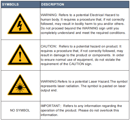
NOTE :
◎ Maxphotonics’ MFSC 3000X-4000X(G4) (Chassis Type) Single Module CW Fiber Laser . It may emit up to 3000X-4000X(G4) average power from 1060nm to
1100nm. This level of light may cause damage to the eye and skin. Despite the radiation being invisible, the beam may cause irreversible damage to the retina.
Laser safety eyewear is not provided with this instrument, but must be worn at all times while the laser is operational.
2-Laser Protection
1、Laser Protection Requirements
You must wear the safety protective glasses while operating the laser, and rationally select the safety protective glasses according to the lasing wavelength
of the laser. If the device is a tunable laser or Raman product, it emits light over a range of wavelengths and the end user should confirm the laser safety
eyewear used protects against light emitted by the device over its entire range of wavelength.
2、Laser Protective Equipment Suppliers
Maxphotonics recommends material or equipments provided by following laser protective equipment suppliers for you, including LaserVision USA, Kentek
Corporation, Rochwell Laser Industries, etc. All the supplier information is provided by Maxphotonics only for the convenience to use, so Maxphotonics
assumes no responsibility for any problem caused by using the products of above mentioned suppliers.
3-Reference Standard
Anti-interference Performance on Electromagnetic Compatibility:
EN 61000-6-4:2007 + A1:2011
EN 61000-6-2:2005 + AC: 2005
EN 61000-3-2:2014
EN 61000-3-3:2013
Power Supply Security:
EN 61010-1:2010
EN60950-1:2006+A11:2009+A1:2010+A12:2011+A2:2013
Laser Security:
EN 60825-1:2014
CDRH 21 CFR 1040.10
NOTE :
◎ In accordance with relevant EU and national standards and requirements, the laser must be classified according to its output power and laser wavelength.
All MFSC-3000W-4000W-Series laser products with high power belong to Class 4 products (according to article 8, EN 60825-1).
4-General Safety Instructions
1、Specular Reflection
There are often numerous secondary laser beams produced at various angles in the output port of the laser. These divergent beams are produced when the
primary beam of laser reflects off a smooth surface, and they are called specular reflections. Although these secondary beams may be less powerful than the
total power emitted from the primary beam, the intensity may be great enough to cause damage to the eyes and skin as well as surface of materials.
WARNING:
◎ You must exercise caution to avoid/minimize specular reflections as these laser radiations are invisible!
2、Safety Instructions of Accessories
The photosensitive elements integrated in laser-related optical accessories may be damaged by laser exposure, such as video cameras, photomultiplier tubes,
and photodiodes. Attention should be paid to related device protection.
WARNING:
◎ The Maxphotonics MFSC laser light is strong enough to cut or weld metal, burn skin, clothing and paint. In addition, this light can ignite volatile substances
such as alcohol, gasoline, ether and other solvents. During the operating process, the flammable materials around the laser must be isolated.
3、Optical Operating Instructions
We strongly recommend that you read the following procedures before operating the laser:
1、Never look directly into the laser output port when the power is turned on.
2、Avoid positioning the laser and all optical output components at eye level.
3、Equip with laser beam casing.
4、Remove the end-cover before switch ON the laser. Or else the output head will be damaged irreversibly.
5、Ensure that all personal protective equipment is suitable for the output power and wavelength range of the laser.
6、Use the laser in a room with access controlled by door interlocks. Post warning signs. Limit the safety areas to operate the laser.
7、Please do not operate the laser in darkened environments.
8、Do not turn on the laser without an optical coupling fiber or an optical output connector.
9、Carry out commissioning, calibration and focusing at low output power and then increase the output power gradually when the calibrating and focusing
work is done.
10、Do not install or detach cutting heads or collimators when the laser is active
11、Make sure that the laser is shut down and the power is off before you install or detach cutting heads or collimators.
12、If the equipment is operated in a manner not specified in this document, the protection devices and performance of the equipment may be impaired and
the warranty will be voided.
CAUTION:
◎ The output of the laser is delivered through a lens with an anti-reflection coating. If the backward-stage light path of your laser has the optical lens, please
strictly inspect the lens of the output head and the backward-stage lens of the laser, and ensure that there is no dust and any other impurity on the lens.
Please note that any macroscopic attachment may cause extreme damage to lens or burn the laser or any backward-stage light path equipment.
◎ For cleaning instructions of the lens, please refer to the “Optical Fiber Connector Inspection and Cleaning Guide”.
◎ Hot or molten pieces of metal may be produced when the laser is under operation. Exercise caution if debris is produced in operation.
◎ When you carry out commissioning and calibration of the laser output, you must set the laser output at low power level and then gradually increase the
output power during checking the quality of the light spot emitted from the laser via an infrared viewer.
WARNING:
◎ Make sure that the individual protective equipment meets the output power and wavelength range of the laser.
◎ Never look directly into the optical fiber or the collimator, and make sure you wear the safety protective glasses in each operation.
4、Electrical Operating Instructions
We strongly recommend that you read the following procedures before operating the laser:
1、Make sure the shell of this equipment is properly grounded. Any interruption of the ground loop may result in personal injury.
2、Make sure the power source connecting equipment is properly grounded.
3、In order to further reduce fire hazard, replace the line fuses (if applicable) with the same types and ratings. The use of other fuses or material is prohibited.
4、Make sure that the input AC voltage of the laser is the voltage of the normal AC mains (Three-phase four-wire 360-440VAC), and wires are connected
accurately. Any incorrect wiring method may cause damage to people or instrument.
5、The equipment does not have any part which can be maintained by operators, and all the maintenance operations must be finished by the professionals of
Maxphotonics Co., Ltd.
6、To prevent electrical shock, do not remove enclosure, detach the laser without permission and damage the relevant signs. Any product with unauthorized
dismounting shall not be subject to warranty.
WARNING:
◎ The input voltage of the laser is triple-phase AC current (360-440VAC), which may cause risk of electric shock. All the relevant cables and connection wires
have potential hazards.
5、Environment Conditions and Precautions
For ensuring the safety of the laser working area, suitable enclosures shall be applied, including but not limited the laser safety signs and the interlocking
devices. Corresponding operators must be trained and examined and know the normal safety specifications for operating the laser.
Meanwhile, it is important that the output components shall not be installed at eye level.
Because of interaction of the laser and the metal material, the radiation of high level ultraviolet light or visible light may be produced. Make sure that the laser
is provided with the protective cover to prevent the eyes or other parts of human bodies from damage by radiation.
We recommend that you comply with the following operating measures to
prolong the service life of the laser:
1、Do not expose the laser to a high moisture environment.
2、Operation at higher temperature will accelerate aging, increase threshold current and lower slop efficiency. If the device is overheated, stop operations
and contact Maxphotonics.
3、Ensure that the work surface is properly vented. There may be gases, sparks and debris generated from the interaction between the laser and the work
surface, and they could pose additional safety hazard.
CAUTION :
◎ The device may be damaged with incautious operation.
◎ If the laser is placed below 0 °C, be sure to add the appropriate proportion of antifreeze to the water cooler. If the machine is not used for a long time, be
sure to drain the water in the water inlet and outlet (high-pressure air gun is recommended) to prevent the residual water from freezing and damaging the
water-passing device.
5-Additional Safety Information
For additional information regarding Laser Safety, please refer to the list below:
Laser Institute of America (LIA)
13501 Ingenuity Drive, Suite 128
Orlando,Florida 32826
Phone:407 380 1553,Fax: 407 380 5588
Toll Free:1 800 34 LASER
American National Standards Institute
ANSI Z136.1, American National Standard for the Safe Use of Lasers (Available through LIA)
International Electro-technical Commission
IEC 60825-1,Edition 1.2
Center for Devices and Radiological Health
21 CFR 1040.10 – Performance Standards for Light-Emitting Products
US Department of Labor – OSHA
Publication 8-1.7 – Guidelines for Laser Safety and Hazard Assessment.
Laser Safety Equipment
Laurin Publishing
Laser safety equipment and Buyer’s Guides
Chapter 3
Product Description
1-Features
MFSC Series CW fiber lasers are compact and efficient high power lasers developed for industrial application. Mainly used in the fields of drilling, cutting
and welding.
Main Features:
1、High-quality laser output
2、High power, high efficiency
3、High reliability, long service life
4、Compact, rugged package
5、Extension programming interface
Applications:
1、Industrial applications
2、Scientific research
2-Module Configuration
Maxphotonics offers many configurable modes. This manual will give complete instructions for all modes, please refer to section 6.3-6.6.
3-Laser Model Designation Codes
| M – F – S – C – XXX – XX 1 – 2 – 3 – 4 – 5 – 6 | ||
| 1 | Manufacturer’s code | M means Maxphotonics |
| 2 | Gain media of the laser | F means Fiber Laser |
| 3 | Laser Module | S means Single Module |
| 4 | Laser state | C means Continue Wave |
| 5 | Maximum output power | XXXX W means the maximum output power of the laser |
| 6 | Additional message | Can be null |
4 – Certification
Maxphotonics certifies that this equipment has been thoroughly tested and inspected and meets published specifications prior to shipping. Upon receiving
your equipment, check whether the packaging and accessories have been damaged in transit. If damage is apparent, please contact Maxphotonics
immediately
5- Front Panel Description
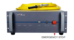
| ITEMS | FUNCTION DESCRIPTION |
| (OFF ON) Key Switch | POWER |
| (EMERGENCY STOP) Emergency Stop Switch | Emergency stop |
| (Start) Start Switch | Start laser (on-off signal of hardware) |
| ALARM | Abnormal situation light of laser |
| ACTIVE | Normal situation light of laser |
| POWER | Power light of laser |
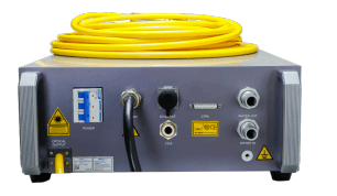
6-Back Panel Description
How to use CDA:
- When using the CDA provided by the customer, the CDA needs to be dried and cooled by a freeze dryer, and filtered through a 5um and 0.3um particle filter and a 0.1um oil mist filter, and the temperature is within the range of 5-40°C.
The highest dew point is 0°C (it is recommended that the compressed air temperature is 5°C lower than the cooling water temperature), the air pressure is
less than 0.1MPa, the flow rate is set to 10LPM, and the interface pipe diameter is 12mm;
- Ventilation should be started 30 minutes before starting up. In winter, when the temperature is lower than 10°C and the humidity is lower than 50%, no
ventilation is required.
| ITEMS | FUNCTION DESCRIPTION |
| CTRL | External control connector |
| ETHERNET | Ethernet interface |
| AC 380V | 360-440VAC power input |
| POWER | 360-440VAC power switch |
| WATER OUT | Water cooling output port(3/4 inch) |
| WATER IN | Water cooling input port(3/4 inch) |
| OPTICAL OUTPUT | Laser output connector |
| CDA | Clean and dry air interface |
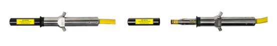
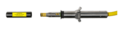
7-Optical Output Terminal
1 、Optical Output Head
The fiber head is used in conjunction with the protection window and can be replaced after damage. Be sure to remove the QBH head and tail cap before
use, which is usually placed with the laser. Refer to “Fiber Connector Inspection and Cleaning Guide” for protective window cleaning supplies and methods.
Optical Output Head (QBH head)
Chapter 4
Specification
1 -Optics Characteristic Parameters
| No. | Characteristics | Test conditions | Min. | Nom. | Max. | Unit |
| 1 | Operation mode | CW/Modulated | ||||
| 2 | Polarization | Random | ||||
| 3 | Output power MFSC-3000X(G4) | 100% CW | 3000 | W | ||
| Output power MFSC-4000X(G4) | 100% CW | 4000 | W | |||
| 4 | Tuning range of output power | 10 | 100 | % | ||
| 5 | Emission wavelength | 100% CW | 1070 | 1080 | 1090 | nm |
| 6 | Spectrum width(3dB) | 100% CW | 3 | 5 | nm | |
| 7 | Short-term power instability | 100% CW>1h | ±1 | ±2 | % | |
| 8 | Long-term power instability | 100% CW>24h | ±3 | ±5 | % | |
9 | Beam quality BPP | 50um-QBH Output | 1.1 | 1.5 | mm x mrad | |
| 100um-QBH Output | 2.8 | 3.6 | mm x mrad | |||
| 10 | Laser switching ON time | 100 | 150 | μs | ||
| 11 | Laser switching OFF time | 100 | 150 | μs | ||
| 12 | Modulation rate | 100%Output | 5 | kHz | ||
| 13 | Red guide laser power | 100%Output | 200 | μW | ||
14 | Feeding fiber cable length MFSC-3000X(G4) | 50um-QBH Output | 20 | m | ||
| Feeding fiber cable length MFSC-4000X(G4) | 50um-QBH Output | 20 | m | |||
| 15 | Feeding fiber core size | 50( 100、200 optional ) | μm | |||
| 16 | Feeding fiber cable bending radius | 200 | mm | |||
| 17 | Output form | Standard QBH(LOC) | ||||
2 -General Characteristic Parameters
| No. | Characteristics | Test conditions | Min. | Nom. | Max. | Unit |
| 1 | Operating voltage | 360 | 400 | 440 | VAC | |
| 2 | Input Power MFSC-3000X(G4) | 100% Output | 10 | |||
| Input Power MFSC-4000X(G4) | 100% Output | 13 | ||||
| 3 | Operating ambient temperature | 100% CW | 10 | 40 | ℃ | |
| 4 | Operating ambient relative humidity | 10 | 85 | % | ||
| 5 | Cooling method | 100% CW | Water-cooling | |||
| 6 | Storage temperature | 100% CW | -10 | 60 | ℃ | |
| 7 | Dimensions | 100% CW>1h | 482.6*850*172 (W*D*H) | mm | ||
| 8 | Weight MFSC-3000X(G4) | 100% CW>24h | 70±3 | kg | ||
| Weight MFSC-4000X(G4) | 50um-QBH Output | 80 ±3 | kg | |||
3-Water Cooling Condition
| No. | Characteristics | Min. | Unit | |
| 1 | Cooling Method | Water Cooling | ||
| 2 | Ambient Temperature | ≥ 30 | < 30 | ℃ |
| Chiller Set Temperature | Summer 26 | Winter 22 | ℃ | |
| 3 | Hydraulic pressure | ≥ 4 | bar | |
| 4 | MFSC-3000X(G4) Water Flow Requirements | 25 | L/ min | |
| MFSC-4000X(G4) Water Flow Requirements | 30 | |||
| 5 | MFSC-3000X(G4) Chiller Rated Cooling Capacity Requirements | 7.5 | KW | |
| MFSC-4000X(G4) Chiller Rated Cooling Capacity Requirements | 10 | |||
CAUTION :
◎ The Chiller needs to meet the requirements of the above table under the conditions of a circulating temperature of 40 ° C and an outlet temperature
of 22 ° C.
◎ The above recommended water pressure requires the pressure drop of the main line Δp ≤ 0.5bar. If this value is exceeded, the main circuit water pressure
should be increased accordingly.
◎ The cooling water and filter element need to be replaced once a month; before winter (referring to low temperature environment of 0° C and below), the
cooling water should be replaced with a suitable antifreeze (for example, glycol antifreeze, excessive addition is strictly prohibited, antifreeze thermal
conductivity coefficient)
Low, excessive addition may cause poor heat dissipation). After the winter is over, the antifreeze should be replaced with distilled water and the filter element
should be replaced to restore the maintenance frequency once a month.
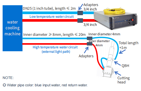
4-QBH Water Cooling Condition
| Cooling Method | Water pipe size requirement | Water Flow Rate (L/min) | Hydraulic pressure (bar) | Cooling Temperature(℃) |
| Water cooling | Outer diameter * inner diameter = Φ6 * Φ4 | ≥ 2 | ≥ 3 | 28-30 |
NOTE:
◎ External light path tube inner diameter ≥ 8mm, length ≤ 20m;
◎ The length of the Φ6 pipe connected to the LOE after switching from the external light path is ≤ 1m;
◎ QBH is connected in series with the cutting head;
◎The above recommended external light path water pressure requires the pressure drop of the cutting head Δp ≤ 1.5bar. If this value is exceeded, the external
light path water pressure should be increased accordingly.
5-Installation Environment Requirements
1.The ambient air cleanliness grade requirement for optical fiber output head installation: 1000 or more stringent grade. Suggestions for Configuration of
Standard Purification Workbench;
2.laser working environment temperature:10°C–40°C;
3.laser working environment humidity:10%-85%;
4.Avoid the condensation environment,the specific control standards are as follows:
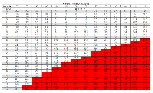
NOTE :
◎ In order to ensure a good operating environment of the laser, to reduce the probability of failure due to condensation. We recommende to prepare an air
conditioned room for the laser, so that the temperature in the air-conditioned room is ≤ 28 °C, and the relative humidity is ≤ 50%. The water cooler should be
placed in a different space from the laser. It is forbidden to place the water cooler in the air conditioned room;
◎ The laser head works at circulating temperature. In order to avoid condensation on the laser head, it is necessary to adjust the temperature of the cooling
water of the external light path to room temperature. It is forbidden to cool the laser head with low-temperature cooling water.
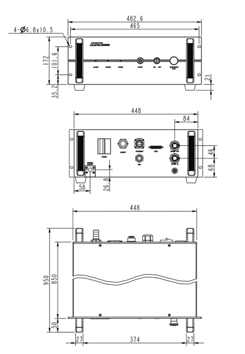
6-Structural Layout
Laser Three Views.(Unit:mm)
Chapter 5
Disassembly Guide
1-Disassembly Step
The laser belongs to the precise valuables, so Maxphotonics recommends the following steps to unpack the packing box.
Please unpack according to the following steps:
- Place the package containing the laser equipment on a horizontal platform, such as a floor or a large table.
- Open the primary box and remove the foam cover,take out the fittings.
- Check the fittings according to the ”Packing List”.
- QBH and fiber optic cable are placed on the top plate of the laser. Please take it out carefully to ensure that the minimum bending radius of the fiber optic cable is >200mm. When taking out, it is recommended that the three people cooperate to operate, two people lift the laser body, and the other person is responsible for taking out the cable.
- Please ensure that the laser is in a dry, ventilated, dust-free environment. The space around the laser is unobstructed. The front of the laser and the operator’s position are unobstructed. There is no obstruction under the laser. There is no dripping on the laser. The laser is located. The position of the drainage is smooth and convenient, and there is no water accumulation.
- Keep all objects after unpacking for future transportation or storage needs.
CAUTION:
◎ If any damage of the external package and internal parts has been found upon receipt of product, please contact Maxphotonics Co., Ltd. or designated
agent immediately.
◎ When the laser is turned off, the water cooler should also be turned off to prevent condensation from occurring due to excessive temperature difference.
RECOMMENDATION:
Change the working temperature or humidity of the laser to keep the laser away from the dew point. (For example, install the laser in an air-conditioned
room.)
2 -Packing List
| No. | Names of fittings | Description | Unit | Quantity |
| 1 | Fiber Laser | MFSC -xxxx | Pc | 1 |
| 2 | External signal wire | Pc | 1 | |
| 3 | Power Keys | Pc | 2 | |
| 4 | Lens cleaning paper | Pc | 4 | |
| 5 | Sample of water pipe of laser | Ф19.1*Ф29mm | Pc | 1 |
| 6 | QBH water pipe sample tube | Ф6x4mm | Pc | 1 |
| 7 | Cable | 10m | Pc | 1 |
| 8 | Hose clamp | American hose clamp, clamping range Ф26-Ф38 | Pc | 2 |
Chapter 6
Operation Guide
1 – Notice
Caution:
◎ Please refer to Section “Detail Specification Table” for proper electrical power.
◎ Refer to Section “General Safety Instructions” for inspecting whether the configuration environment of peripheral work of the laser meets the requirements.
2 – Electrical Power Connection
The laser power input line needs to be connected to three-phase four-wire AC.
Make sure that the live wire is properly connected according to the wire mark and the ground wire is well connected. Poor contact of the ground wire may
cause potential damage to the laser.
For ensuring the safety feature, Maxphotonics recommends you connect a 32A circuit breaker (air switch) in series between the power supply unit and the
laser.
This electric power shall be in close proximity to the power supply unit of the equipment and can be easily disconnected.
Refer to Section “Detail Specification Table” to determine your electrical specification if you have any problem about wiring.
3- Extension Interface
Laser The CTRL interface is a high quality DB25 interface that provides a variety of signals for functional control of the laser, as described below:
3000X-4000X(G4) DB25 interface
| Ctrl Interface Pin | Wire Color | Function Description | Notes |
| 18 | Red | Enable input + | HIGH:20VDC ≤ V ≤24VDC LOW:0VDC ≤ V ≤ 5VDC 5mA ≤ I ≤15mA |
| 5 | Red And White | Enable input – | |
| 17 | Black | Modulation input + | HIGH:20VDC ≤ V ≤24VDC LOW:0VDC ≤ V ≤ 5VDC 5mA ≤ I ≤15mA |
| 4 | Black And White | Modulation input – | |
| 16 | Yellow | External light + | Connect dry contact control |
| 3 | Yellow Black | External light – | |
| 15 | Green | DA (0-10V) input + | Control laser output power (1V-10%, 10V-100%) |
| 2 | Green And White | DA (0-10V) input – | |
| 14 | Brown | Fault output 1 | Dry contact output, ON fault, OFF- normal, (contact voltage V ≤ 30VDC, contact current I ≤ 100mA) |
| 1 | Brown And White | Fault output 2 | |
| 19 | Light blue | Emergency stop input 1+ | HIGH:20VDC ≤ V ≤24VDC LOW:0VDC ≤ V ≤ 5VDC 5mA ≤ I ≤15mA |
| 6 | Light blue black | Emergency stop input 1- | |
| 20 | Orange | Interlock+ | Connect dry contact control (shorted by default) |
| 7 | Orange black | Interlock- | |
| 21 | Purple | Reset+ | HIGH:20VDC ≤ V ≤24VDC LOW:0VDC ≤ V ≤ 5VDC 5mA ≤ I ≤15mA |
| 8 | Purple black | Reset- | |
| 22 | Light green | Emergency stop output 2A | Dry contact output, ON Emergency stop output, OFF- normal, (contact voltage V ≤ 30VDC, contact current I ≤ 100mA) |
| 9 | Light green black | Emergency stop output 2B | |
| 10 | Blue | Emergency stop input2+ | HIGH:20VDC ≤ V ≤24VDC LOW:0VDC ≤ V ≤ 5VDC 5mA ≤ I ≤15mA |
| 23 | Blue and white | Emergency stop input2- | |
| 24 | Gray | Key switch+ | Connect dry contact control |
| 11 | Gray black | Key switch- | |
| Shell | Yellow-green | Ground wire |
4-Start Steps
WARNING:
◎ Make sure that all the electrical connections (including cooling water connections) are connected prior to use. All the connectors must be held steady
with screws if possible.
◎ When operating the laser, do not directly look at the output fiber and wear safety glasses. When wiring, please turn off all power switches of the laser.
Start steps are as follows:
1、Start the Chiller;
2、Remove the end cap of the collimator;
3、Make sure that the end surface of the collimator is clean and not covered with impurities;
4、Make sure that the emergency stop switch is turned on;
5、 Turn the rear panel power switch (POWER) to the ON position;
6、Place the Key Switch of the front panel on position “ON”;
7、Press the START button on the front panel.
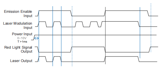
5-Mode Description
The working modes of the laser are as follows:
- Continuous mode: the emitted light is continuous and can be used for cutting.
- Pulse mode: The emitted light is pulsed. When the pulse frequency is greater than a certain value, the actual application is used to control the average output power of the laser (pulse width adjustment, when the external control, the modulation signal corresponds to the mode).
external control: specific parameter settings through the board software interface.
External Control Signal Timing
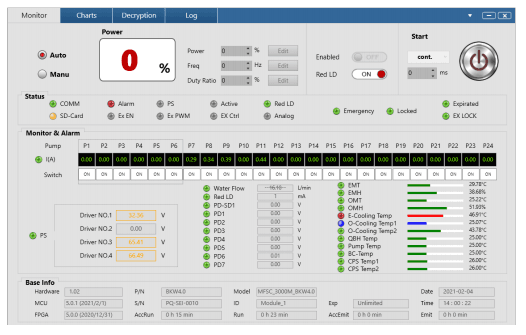
6-Software Description
(1) Enter “Chuangxin Laser Official Website”-“Download Center”-“Install Software”, and download “G3 Series-Software Installation Guide”, “NET4.6”,
“G3-Series-n.n.n.n”. (The version is updated from time to time, subject to the official website announcement without notice.)

(2) Decompress the downloaded compressed package, and install the operating environment (NET4.6) and monitoring software (G3-Series-n.n.n.n) referring to
the “G3 Series-Software Installation Guide”. (Win10 system or system with .NET 4.6 installed, no need to install NET4.6).
(3) After installing the operating environment and monitoring software, a “G3- Series” shortcut will appear on the desktop.

(4) Check the communication interface of the laser backplane, which is the EtherNet interface, and connect it to the computer, and power on the laser.
(5) Double-click the desktop “G3-Series” shortcut to open the monitoring software and enter the following connection interface.
(6) If the laser backplane is an EtherNet interface, select the communication mode of the monitoring software as IP2, enter the laser IP address (default is
192.168.0.178), and click the “Login” button to try to connect with the laser.
If the laser is powered on and the model can match the monitoring software, it will enter the following monitoring interface.
(7) Click the “Login” button to connect the laser and enter the following monitoring interface.
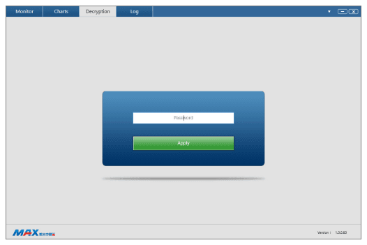
(8) Decrypt the page.
Tips: For the specific details of software installation and instructions, please refer to the relevant instructions of the official website software.
7-Error List
The fault alarm points set by the laser include:
| No. | Message | Description | Trouble shooting |
| 1 | PD alarm | Laser internal light path testing fault | Operation leads to low output power of laser such as low modulation frequency, low peak power, low cutting power. |
| 2 | Water flow warning of the chiller | The chiller is not started or water flow is not sufficient | Start the chiller and make sure that there is sufficient water flow in the water line. |
| 3 | Overheat alarm | Overheat fault of the laser | For the internal overheat fault of the laser, please check whether the preset temperature of the chiller meets the requirements. Shut down the laser and do not restart it until the heat accumulated during operation dissipates thoroughly. |
| 4 | Overcurrent alarm | Overcurrent fault of the laser | If ”0-10V” DA value exceeds the preset value, the internal overcurrent fault will occur. |
| 5 | QBH installation alarm | Install error of the QBH | The fault will be produced when QBH head is not inserted into the cutting head or at the wrong place. |
| 6 | Emergency stop alarm | The emergency stop switch is pressed | Release the emergency stop switch, the laser will work again after being restarted. |
Note:
◎ All the alarm message will be displayed on the Monitor Software. Please pay attention and contact our service personnel if you need.
Chapter 7
Fiber Connector Inspection and
Cleaning Guide
1-Notice
It is imperative that the fiber connector is checked for dust, dirt, or damage every time it is connected to any optical device, before use. The use of a
dirty or damaged fiber connector can result in serious injury and/or laser damage. Maxphotonics is not responsible for any damage due to contaminated
connectors.
For cleaning a fiber connector, you need the following materials:
1、Powder-free rubber gloves or fingerstall
2、Lint free optical cleaning wipes and/or swabs
3、Ahydrous ethanol (Optical level, pure >99.5%)
4、Acetone (Optical level, pure >99.5%)
5、Compressed air (oil free, water free)
6、Microscope
7、Light source
IMPORTANT :
◎ It is imperative that you wear powder-free rubber gloves during this cleaning procedure! It is hereby stated that damage to the fiber connector can occur
due to mishandling, the use of incorrect cleaning procedures, or chemicals for cleaning. This is not covered by the Maxphotonics’ warranty. Ahydrous ethanol
and acetone should be managed and stored according to the local law and instructions.
2-Operating Procedures
Clean and maintain the fiber laser according to the following procedures:
1、Switch off the laser power, and place the key switch on position of “OFF”
2、Remove the black outer protective sleeve and leave the white inner cap on and clean the fiber connector exterior with optical cleaner, wipe it with a clean
optical wipe and dry it with compressed air;
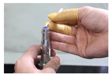
3、Place fiber connector in the holder of the microscope;(7-1)
4、Remove the protective inner cap from the connector;(7-2)
5、Focus the microscope onto the connector surface;
6、Use a light source to illuminate the face of the fiber connector so that the light is reflected off the surface of the endface. This is achieved if you see a
bright golden shine from the QBH connector endface.
7、Inspect the endface surface carefully. Contamination will lead to dark spots/burns on the surface and possibly damage to the fiber and/or laser. If
contamination is visible on the endface, cleaning is necessary.
8、Take out the cap and sleeve, then connect the fiber connector with the cutting head quickly and fasten them. (Place the cap face down on a clean surface
or a lint-free wipe.)
7-1 Remove the fiber protective sleeve and protective film
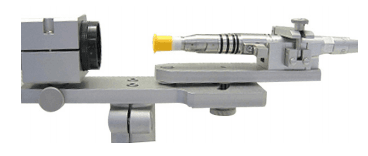
7-2 Install the fiber connector under microscope
7-3 Cleaning protective lens with swabs
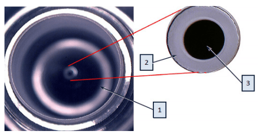
1、quartz 2、fiber cladding 3、fiber core
7-4 Actual image of the fiber
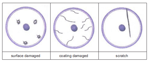
7-5 Endface may be damaged
IMPROTANT :
◎ Do not reuse a lint-free optical wipe or swab.
◎ Do not touch the protective lens of the fiber connector.
◎ Do not blow directly, or else new dirty will be brought.
◎ Do not touch the tip of the cleaning swab with your fingers.
◎ Cleaning is necessary before place the protective cover and sleeve.
◎ Never blow air directly at the surface, because you could imbed contaminants into the surface. Always blow across the surface!
◎ If the fiber connector could not be installed in optical system immediately, please cover it with the protective cap cleaned with compressed air.
CAUTION :
◎ It is hereby stated that damage to the fiber connector can occur due to mishandling, the use of incorrect cleaning procedures, or chemicals for cleaning.
This is not covered by the Maxphotonics’ warranty.
Chapter 8
Service and Maintenance
1-Maintenance Notes
CAUTION :
◎ No operator serviceable parts inside. Refer all servicing to qualified Maxphotonics personnel.
◎ For ensuring that the repairs or replacement within the warranty scope can be carried out, and perfectly maintaining your interests, please submit application
to the Maxphotonics or the local representative after finding the faults. Upon receiving our authorization, you need to pack the product in a suitable package
and return it.
◎ You should keep the proof when finding any damage after receiving the product, so as to claim the rights to shippers.
IMPORTANT :
◎ Do not send any product to Maxphotonics without RMA.
◎ If the product is beyond the warranty period or the warranty scope, customers shall be responsible for the repairing cost.
CHANGE :
◎ We have the rights to change any design or structure of our product, and the information is subject to change without notice.
2-Service Statements
More problems regarding the safety, set-up, operation or maintenance please reading this “User Guide” carefully and flowing the operation steps stictly.
Please call the Customer Service Department for other questions.
Your problems will be follow-up by our technical support group after verified.
If the problems cannot be solved , you may need to return the product to Maxphotonics for further troubleshooting.
Chapter 9
Warranty Statements
1-General Clauses
Maxphotonics Co.,Ltd. carries out warranty for any defect of the product caused by its material and production technology within the warranty period agreed
in contract, and ensures that its product meet the relevant quality and specification requirements specified in the document under normal use condition.
Maxphotonics Co.,Ltd. rationally determines to repair or replace the products with faults caused by its material or production technology within the warranty
period, and repairs or replacement of all the products within the warranty scope are carried out according to the rest of the warranty period of primary
products.
2-Warranty Limitations
Under the following circumstances, the products, parts (including the fiber connectors) or equipment are not within the warranty scope:
(1)Tampered, opened, detached or reconstructed by personnel outside Maxphotonics;
(2)Damaged from misuse, neglect or accident;
(3)Used beyond the specification and technical requirements of the product;
(4)Indirectly damaged from users’ software or interfaces;
(5)Improper installation or maintenance, or operating under conditions not included in this manual;
(6)The fittings and the fiber connectors are not included in the warranty scope.
Customers are obligated to understand the information above and operate according to the User Guide and specification, or the faults arising there from are
not included in the warranty scope.
IMPORTANT:
◎ Within the warranty scope, purchasers must feed back within 31 days after finding the product defect.
◎ Maxphotonics does not grant any Third Party rights to repair or replace the parts, the equipment or other Maxphotonics products.
Where to Buy fibre laser cutting machine in the World?
Krrass was established in Singapore, formely GMS, and its production based in China was established in 1998. Our company deals in machinery and tools related to sheet metal fabrication. Partnering with world-renowned manufacturers, we are always on the lookout for user-friendly solutions to all your metal forming needs. If you need to know more about the bending machine, please click: fibre laser cutting machine