
High Power Fiber Laser CUT Series
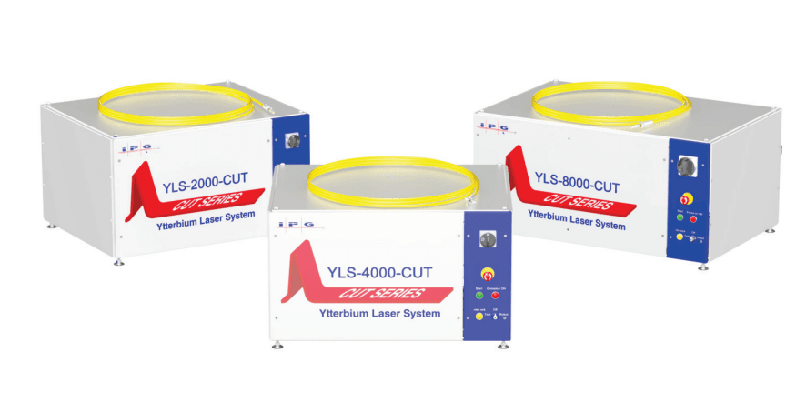
Table of contents
1 General information ………………………………………………………….1
1.1 Manufacturer……………………………………………………………………………….2
1.2 EC Declaration of Conformity …………………………………………………..3
1.3 Target groups for this operating manual ……………………………….3
1.4 Warranty………………………………………………………………………………………3
1.5 Formal information about the operating manual…………………5
1.6 Presentation of safety instructions………………………………………….6
1.7 Layout conventions…………………………………………………………………….8
1.8 Abbreviations………………………………………………………………………………9
1.9 Licensing agreements …………………………………………………………….. 10
2 Safety………………………………………………………………………………… 13
2.1 Safety instructions…………………………………………………………………… 13
2.2 Intended use…………………………………………………………………………….. 13
2.3 Unintended use………………………………………………………………………… 14
2.4 Obligations of the system owner………………………………………….. 14
2.5 Responsibility of the operating personnel………………………….. 15
2.6 Personnel qualifications ………………………………………………………… 15
2.7 Safety-conscious working ……………………………………………………… 16
2.8 Personal protective gear………………………………………………………… 16
2.9 Specific dangers……………………………………………………………………….. 17
2.9.1 Laser radiation ……………………………………………………………………… 17
2.9.2 Electrical energy…………………………………………………………………… 18
2.9.3 Gas and particle emission …………………………………………………… 18
2.10 Safety equipment…………………………………………………………………….. 19
2.10.1 E-Stop button………………………………………………………………………… 21
2.10.2 External safety interface……………………………………………………… 21
2.10.3 Fiber break monitoring……………………………………………………….. 21
2.10.4 Leakage sensors……………………………………………………………………. 21
2.11 Safety labels……………………………………………………………………………… 22
2.12 Independent alteration or replacement parts procurement …………………………………………………………………………………………………….. 23
3 Device description………………………………………………………….. 24
3.1 Overview…………………………………………………………………………………… 24
3.1.1 Operating elements ……………………………………………………………… 25
3.1.2 Interfaces and connections…………………………………………………. 26
3.1.3 Main components…………………………………………………………………. 27
3.1.4 Electrical mounting plate……………………………………………………. 28
3.2 Functional principle………………………………………………………………… 29
4 Delivery and transport ………………………………………………….. 31
4.1 Scope of delivery……………………………………………………………………… 31
4.2 Delivery and transport …………………………………………………………… 31
4.2.1 Unloading ………………………………………………………………………………. 32
4.2.2 Unpacking the product………………………………………………………… 33
4.2.3 Transport to the installation site ………………………………………. 34
5 Assembly and installation …………………………………………….. 36
5.1 Space requirements and room conditions………………………….. 36
5.2 Supply connections…………………………………………………………………. 37
5.2.1 Supply voltage ………………………………………………………………………. 37
5.2.2 Cooling water supply …………………………………………………………… 38
5.3 Setting up the laser …………………………………………………………………. 38
5.4 Running lines and fibers………………………………………………………… 39
5.5 Connecting the laser……………………………………………………………….. 40
5.5.1 Connecting the water supply……………………………………………… 41
5.5.2 Connecting the supply voltage…………………………………………… 44
5.5.3 Connecting the external interfaces……………………………………. 45
5.5.4 Connecting the fiber connector to the process optics……. 46
5.6 Installing the software……………………………………………………………. 47
6 Acceptance and commissioning …………………………………… 48
6.1 Visual inspection……………………………………………………………………… 48
6.2 Work to be performed before commissioning…………………… 48
6.3 Transfer to operation……………………………………………………………… 49
6.4 Recommissioning ……………………………………………………………………. 49
7 Operation…………………………………………………………………………. 50
7.1 Operating modes……………………………………………………………………… 50
7.2 Switching on/off ……………………………………………………………………… 51
7.3 Switching on the main power supply ………………………………….. 52
7.4 TEST mode ……………………………………………………………………………….. 53
7.4.1 Working without the laser program…………………………………. 54
7.4.2 Working with the laser program……………………………………….. 55
7.4.3 External control ……………………………………………………………………. 55
7.4.4 Analog control ………………………………………………………………………. 57
7.5 ROBOT mode ……………………………………………………………………………. 58
8 Maintenance ……………………………………………………………………. 61
8.1 Maintenance work…………………………………………………………………… 62
8.1.1 Clean fiber connectors…………………………………………………………. 62
8.1.2 Measuring the laser output power……………………………………. 70
8.1.3 Measuring the beam quality……………………………………………….. 70
8.2 Replacement and repair work………………………………………………. 71
8.2.1 Replacing a laser module ……………………………………………………. 71
8.2.2 Replacing the feeding fiber…………………………………………………. 71
8.3 Water system (IPG chiller)…………………………………………………….. 71
9 Messages and troubleshooting …………………………………….. 72
9.1 Information about message displays…………………………………… 72
9.2 Status messages, warning messages and alarms ………………. 72
9.3 Troubleshooting………………………………………………………………………. 72
9.4 Manufacturer service ……………………………………………………………… 73
9.4.1 Behavior in the event of malfunctions……………………………… 73
9.4.2 Downloading the log files via LaserNet……………………………. 74
9.4.3 Downloading the events file via LaserNet……………………….. 77
9.4.4 Downloading the configuration overview via LaserNet .. 79
9.4.5 Updating the firmware and laser configuration……………… 80
9.4.6 Resetting critical errors………………………………………………………. 82
10 Decommissioning and disposal……………………………………. 83
10.1 Temporary shutdown…………………………………………………………….. 83
10.2 Final shutdown………………………………………………………………………… 84
10.3 Disposal…………………………………………………………………………………….. 85
11 LaserNet software…………………………………………………………… 86
11.1 System requirements……………………………………………………………… 86
11.2 Installing the software……………………………………………………………. 86
11.3 Establishing a connection to the laser…………………………………. 89
11.4 Starting LaserNet…………………………………………………………………….. 91
11.5 LaserNet user interface………………………………………………………….. 92
11.6 LaserNet menu structure……………………………………………………….. 94
11.6.1 File…………………………………………………………………………………………… 95
11.6.2 Configuration ………………………………………………………………………… 96
11.6.3 View……………………………………………………………………………………….105
11.6.4 Extras …………………………………………………………………………………….106
11.6.5 Help………………………………………………………………………………………..107
11.7 LaserNet status indicators ……………………………………………………108
11.8 LaserNet tabs ………………………………………………………………………….108
11.8.1 Status tab………………………………………………………………………………108
11.8.2 Alarms tab…………………………………………………………………………….110
11.8.3 Warnings tab………………………………………………………………………..110
11.8.4 Control tab ……………………………………………………………………………111
11.8.5 Events tab……………………………………………………………………………..113
11.8.6 Logfiles tab……………………………………………………………………………114
11.8.7 Power supply tab…………………………………………………………………114
11.8.8 Chiller tab……………………………………………………………………………..115
11.8.9 Dew point tab……………………………………………………………………….117
11.8.10 Hardwiring tab…………………………………………………………………….118
11.8.11 Modules tab ………………………………………………………………………….118
11.9 LaserNet program editor (LP editor) …………………………………119
11.9.1 LaserNet program editor editing window………………………119
11.9.2 Command list for laser programs …………………………………….121
11.9.3 LaserNet program editor command descriptions…………122
Annex A Status, warning and fault messages ……………………..125
Status tab ……………………………………………………………………………………………..127
Alarms tab ……………………………………………………………………………………………129
Warnings tab ……………………………………………………………………………………….141
Control tab……………………………………………………………………………………………146
Power supply tab………………………………………………………………………………..147
Chiller tab (IPG laser chiller)…………………………………………………………….149
Dew point tab………………………………………………………………………………………162
Fieldbus tab………………………………………………………………………………………….163
Annex B Technical data………………………………………………………….164
Dew point temperatures……………………………………………………………………164
Rating plates………………………………………………………………………………………..165
Annex C Declaration of Conformity……………………………………..166
Original Declaration of Conformity …………………………………………………166
Translation of the Declaration of Conformity………………………………..167
Annex D Indices of figures and tables………………………………….168
List of figures……………………………………………………………………………………….168
List of tables…………………………………………………………………………………………171
1 General information
This operating manual enables safe and efficient operation of the
high power fiber laser (hereafter also referred to as the product). It
is part of the product and must be kept in the product’s immediate
vicinity and accessible to the operating personnel at all times.
The operating manual contains all important information about
assembly, commissioning, operation and maintenance of the product.
The operating and maintenance personnel must have carefully read
and understood this operating manual before beginning any work.
The safety instructions in this operating manual must be followed.
Failure to follow the safety instructions can lead to personal injuries,
damage to the device or environmental damage.
1.1 Manufacturer
| Registered office in Germany | IPG Laser GmbH Siemens strasse 7 D- 57299 Burbach |
1.2 EC Declaration of Conformity
The declaration of conformity of the product can be found in the
appendix to this operating manual.
1.3 Target groups for this operating manual
The original operating manual was created by IPG Laser GmbH for
the operating and maintenance personnel of the system owner.
The operating personnel must have corresponding vocational
training in metalworking and be trained in operation of the product.
The maintenance personnel is responsible for the
assembly/installation, maintenance and repair. The personnel must
have been trained in maintenance of the product by IPG Laser GmbH
or another competent IPG branch office. Successful participation in
the training is confirmed with a certificate.
1.4 Warranty
IPG Laser GmbH offers a warranty for all of it products with regard
to material and manufacturing defects for the period specified in the
applicable purchase contract or in the technical data; the warranty
period begins on the date of delivery agreed upon in the purchase
contract.
In addition, IPG Laser GmbH guarantees that this product satisfies all
applicable technical data in normal operation.
During the warranty period, IPG Laser GmbH may choose to repair
or replace a product that is found to be defective in the opinion of
IPG Laser GmbH with regard to material and manufacturing defects.
| Warranty period | The warranty period for all products repaired or replaced during the warranty period is limited to the remaining period of the original warranty period and is only offered for the individual defective product. IPG Laser GmbH reserves the right to issue a credit for all defective products that have proven to be faulty during normal operation. ⇒ Contact qualified IPG personnel for all maintenance work. All inquiries in connection with repairs or replacements within the framework of this warranty must be made immediately after the defect was discovered; such inquiries must be made directly to IPG Laser GmbH or its local representative. |
| Driver software | Current and future software is subject to the non-exclusive licensing conditions of IPG Laser GmbH. Using the software automatically constitutes acceptance of the licensing conditions. |
| Service and repairs | When sending back components / products, observe the following instructions: obtained from the Service department of IPG Laser GmbH. . The costs for the repair of the product will be invoiced to the customer if the product or the repair is not covered by the warranty. . Never send a product back to IPG Laser GmbH without enclosing a valid RMA1 number. The RMA number can be . Articles that are sent back to IPG Laser GmbH upon request must be shipped in a suitable container / packaging. |
| Protection class | Voiding of the warranty The specified IP protection classes apply only for the closed cabinet and with use of the connections and couplings provided. ⇒ Always keep the cabinet closed during operation. ⇒ Do not make any mechanical alterations to the connections. |
| Changes | The IP protection classes specified in the technical data apply to the electrical and electronic components of the product. Mechanical changes can lead to a lower protection class, thereby voiding the warranty. IPG Laser GmbH reserves the right to make changes to the design or construction of its products at any time without any obligation to implement or install these changes in units purchased at an earlier point in time. |
1.5 Formal information about the operating manual
IPG Laser GmbH grants no usage rights, either directly or indirectly,under a patent or other industrial property rights or copyright on the basis of the use of information provided in this document.
Copyright 2015 IPG Laser GmbH. All rights reserved.
Without the express written authorization of IPG Laser GmbH, it is prohibited to reproduce this publication, share it with third parties, store it in retrieval systems or adapt it in any way whatsoever.
| Service | In the event of faults that cannot be rectified using this operating manual, please contact the competent IPG service department (see section 9.4.1). IPG Laser GmbH believes that the information provided is correct and reliable. IPG Laser GmbH provides no warranty of any kind,except with regard to the information in this document, including the assurance of suitability for general or specific use. Furthermore, IPG Laser GmbH accepts no responsibility for the use of information in result from the use of this information. |
| Accompanying documents | In addition to this operating manual, the complete user documentation includes the following: Commissioning report Circuit diagram Layout of the installation panel Accessories list Technical data Additional system documents in accordance with contractual agreements. |
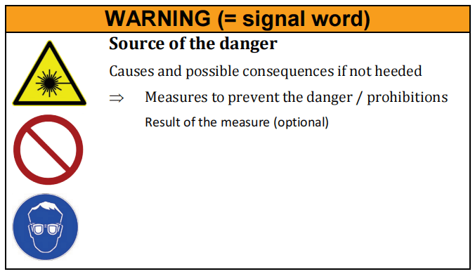
1.6 Presentation of safety instructions
Warnings
. Protect against possible injuries and property damage, if heeded.
. Indicate the magnitude of the danger by means of the signal word.
. Indicate the risk of personal injury with the danger symbol.
. Describe the type and source of the danger.
. State the risk and possible consequences.
. Present measures for avoiding dangers and prohibit specific
actions.
General
warnings
Safety symbols
Safety symbols are displayed in the left column of the warning:
. The warning sign designates warnings that warn against personal injury.
. The prohibition sign indicates an action that may not be performed.
. The mandatory sign indicates a required action that must be performed to prevent danger.
Signal word
The selected signal word indicates the magnitude of a potentialdanger and the probability of its occurrence.
Source of the danger
The type and cause of the danger are specified here.
Possible consequences of failure to heed the warning
The possible consequences of failure to heed the warning are, forexample, crushing injuries, burns or other severe injuries. Additionalexplanations can also be given here.
Measures / prohibitions
Actions that must be taken to avoid a danger or that are prohibited in order to avoid a danger are listed under measures / prohibitions.
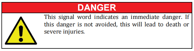
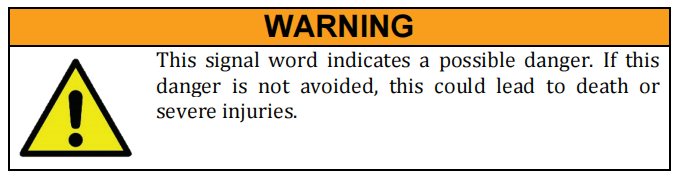
Signal words

Additional
instructions
1.7 Layout conventions
Various symbols and numbering styles are used in this operatingmanual in order to designate actions, lists, status descriptions, etc.The most important layout conventions are listed below.
| Content | Depiction in the text |
| Instructions to be followed in a specific order | 1.Action 1 2.Action 2 |
| Individual instruction, instruction with a specific order and indication of the result | ⇒ Action Condition/result after performance of the action oradditional explanation |
| List without a specific order | . List item |
| List with specific order | (1) First list item (2) Second list item |
| Softkey buttons or keyboard | Softkey button |
| Menu Title | Menu Title |
| Menu path | Menu 1 Menu 2 Command |
| System messages, signal names | Message text |
| Operating modes | ROBOT |
1.8 Abbreviations
| Abbreviation | Meaning |
| DI | De-ionized (DI water) |
| dH | German hardness (unit of water hardness) |
| Δpmax | Maximum pressure difference |
| FBUS | Fieldbus |
| IP | Internet protocol |
| LAN | Local area network |
| LED | Light-emitting diode |
| MPI | Multi-port interface |
| PE | Protective earth conductor |
| PF | Process fiber |
| QD | Connector standard (laser) |
| RMA | Return material authorization |
| TCP/IP | Transmission control protocol / Internet protocol |
| VAC | Volt alternating current |
| VDC | Volt direct current |
| VDE | Association for Electrical, Electronic & Information Technologies (Verband deutscher Elektrotechniker) |
| YLS | Ytterbium laser system |
1.9 Licensing agreements
Software licensing agreements for LaserNet
IPG Laser GmbH®
Single user license

SOFTWARE LICENSING AGREEMENT
Read the conditions of this software licensing agreementcarefully before using the software.
IPG Photonics and/or itssubsidiaries IPG Laser GmbH (hereafter “IPG”) grants you as the end
user a usage license only under the condition that youaccept all conditions of this licensing agreement.
A legal contract enforceable by law is hereby established betweenyou and IPG.
Through a written declaration of acceptance, you accept the conditions of this agreement.
License
The software licensed by this agreement (collectively “Software”) is
the property of IPG and is protected by copyright. Once you have
accepted this licensing agreement, you receive certain usage rights
for the software. This license regulates all versions, revisions or
improvements to the software that IPG may make available to you.
Except as modified by an IPG license document, a license certificate
or a license key that precedes, follows or is enclosed with this
license, your rights and obligations with respect to the use of this
software are as follows:
You may:
. Use the software on a single computer (Windows operating
system).
. Create one copy of the software for archiving purposes or copy
the software to the hard drive of your computer and keep the original for archiving purposes.
You may not:
. Issue a sublicense for any portion of the software, lease or lend
out the software; furthermore, you may not disassemble,
decompile, take apart, modify or translate the software or
attempt to decrypt the source code of the software or create
works derived from the software.
. Use previous versions of the software after you have received a
replacement set of CDs or an updated version. After updating of the software, all copies of the previous versions must be
destroyed.
. Use a later version of the software than is granted to you via
this licensing agreement, unless you have purchased
permission to update or otherwise acquired in a separate form
the right to use such a later version.
. Use IPG software on data carriers for which you have no
permission within the scope of a license module.
. Use the software in a way that is not permitted by this license.
Use of the
software and
updating
IPG provides the software only in connection with a fiber laser of the
company IPG.
Specific IPG software products contain content that is updated from
time to time. You can receive updates to the content for the period
for which you have subscribed to updates to the content (including
each subscription that is included upon purchase of the software),
purchased update rights for the software or concluded a
maintenance agreement that includes updates to the content or for
which you have otherwise purchased the right to receive updates to
the content. This license does not entitle you to receive or use
updates to the content in any other form.
Warranty
IPG offers no warranty that the data carrier on which the software is
sold is free of errors. Your sole remedy in the event of a violation of
this warranty is that IPG, at its own discretion, will replace faulty
data carriers that are returned to IPG within the warranty period.
IPG offers no warranty that the software will meet your
requirements or that the operation of the software will be without
disruptions or that the software is free of errors.
The above warranty applies exclusively and in the place of all other
warranties, regardless of whether express or implicit, including the
implicit warranty with regard to the general suitability for use,
suitability for a specific purpose and in regard to the non-violation of
rights to intellectual property.
Exclusion of
liability in the
event of
damages
IPG accepts no complaint or claim of damage originating from the
use of the software.
IPG is, as permitted in maximum form by the applicable laws and
independent of whether a remedy depicted in this document fails in
its primary purpose, not liable to you in any case for special
consequential, direct or similar damages, including lost profit or loss
of data, even if IPG was informed of the possibility of such damage.
In no case shall the liability of IPG or its licensors exceed the
purchase value of the software.
Limited rights
All products and documentation of IPG are commercial in nature.
The software and software documentation are “commercial articles”.
Export
The export or re-export of this software is regulated in each case by
the locally applicable laws and regulations. The export or re-export
of the software to an entity on the list of prohibited trade partners
and other blacklists published by the various public authorities is
strictly prohibited.
General
information
This agreement and every license module associated with it
represents the entire agreement between you and IPG with regard to
the software and replaces all previous or simultaneously established
oral or written agreements, proposals and representations in regard
to this issue; it takes priority over all contradictory and
supplemental conditions of every offer, every order, every
confirmation or similar agreement between the parties.
This agreement shall be terminated by a violation of the conditions
contained herein; in this case, you must cease use of the software and
destroy all copies of the software. The exclusion of liability in regard
to warranties and damages as well as the restrictions of liability remains in effect even after termination of the agreement. This
agreement can only be modified by a license module that is enclosed
with this license and/or by a written document that has been signed
by you and IPG. If you have questions concerning this agreement or
would otherwise like to contact us, please write to IPG.
2 Safety
The product was designed, manufactured and tested for safetyaccording to the currently applicable safety rules and laws and current engineering practices.
The product is in a technically fault- free condition.
However, the product can pose dangers when it is
. operated by personnel without proper training.
. used improperly or contrary to the intended use.
. not in a fault-free condition from a safety perspective.
2.1 Safety instructions
Normal
operation
Operation of the product is only permitted if all safety equipment is
in operation.
Access to the work zones must be secured with isolating protection
equipment with safety interlock function (laser cell) such that the
area outside the work zones satisfies the requirements of laser
class 1.
The laser cabinet must always be closed and locked during
operation.
Maintenance
Maintenance work may only be performed by trained experts.
The product may not be operated with electrical connections that are
faulty or not ready for operation.
The laser cabinet must always be closed and locked after
maintenance work. Access may only be permitted to authorized and
appropriately trained personnel who have received safety training.
In event of faults in the energy supply, the product must be switched
off immediately.
The inspection and maintenance intervals specified by the
manufacturers for electrical and mechanical components must be
complied with.
2.2 Intended use
The product is intended exclusively for material processing, inparticular for cutting and welding applications on metals and metal alloys.
2.3 Unintended use
The operational safety of the supplied product is only guaranteed ifthe intended use is complied with. The limit values specified in thetechnical data may not be exceeded under any circumstances. Theuse of optics (e.g. fiber coupler, process fiber, process optics) that arenot authorized by IPG is not covered by the warranty.
2.4 Obligations of the system owner
The system owner must ensure that the safety and health of theoperating personnel are always protected during use of the product.
The system owner must in particular ensure that
. the product is used only as intended (see section2.2).n 2.2).
. the product is used only in a flawless, properly functional condition.
. all safety and warning labels are affixed to the product and remain readable.
. appropriate fire protection is present at the setup location.
. the safety equipment is always kept freely accessible and is regularly inspected.
. only properly trained or educated personnel operate, maintain or repair the product.
. the responsibilities of the assigned personnel are defined and complied with.
. the operating personnel has completely read and understood the operating manual and knows all the safety instructions and residual dangers described in the operating manual.
. first aid is made possible for the operating personnel (e.g. through first aid training and appropriate first aid equipment).
. the personal protective gear is available to the operating and maintenance personnel and used in accordance with the applicable regulations.
. the operating personnel are not under the influence of drugs, alcohol or medications that reduce reaction speed.
. the safety- and risk-conscious work of the personnel is regularly inspected.
. the specified maintenance and inspection work is performed on time.
. in addition to the instructions in this manual, the rules and regulations for accident prevention as well as the environmental and occupational safety regulations of public authorities and industry associations applicable at the usage site are complied with.
. electrical work is only performed by qualified electricians.
. the operating manual is available for consultation at the usage site of the product at all times and is in a readable condition.
2.5 Responsibility of the operating personnel
Every operator of the product
. must follow the fundamental rules with regard to safety- conscious work, accident prevention and the operation of the product.
. must know the currently applicable statutory provisions on laser safety.
2.6 Personnel qualifications
The personnel assigned to assemble, maintain, operate and inspectthe product must have the corresponding qualifications forperforming this work.
The areas of responsibility, competency and supervision of thepersonnel must be precisely regulated by the system owner.
Any lack of knowledge on the part of the personnel must becorrected through training and instruction.
Operating
personnel
The operating personnel must have corresponding vocational
training in metalworking and be trained in operation of the product.
During operation on an industrial robot, the operating personnel
must be capable of operating the robot used (training generally
provided by the robot manufacturer).
The operating personnel may only:
. operate the product
. carry out cleaning work (except for cleaning of the fiber
connector)
Maintenance
personnel
The maintenance personnel is responsible for the
assembly/installation, maintenance and repair. The personnel must
have been trained in maintenance of the product by IPG Laser GmbH
or another competent IPG branch office, unless this work is
performed by employees of IPG Laser GmbH.
The maintenance personnel consists of experts who have the
corresponding qualifications for performing the work listed below.
After corresponding training by IPG, the maintenance personnel
may:
. Clean fiber connectors
. Replace components
. Perform adjustment work
All other work may only be performed by employees of the
competent IPG service department itself or by appropriately
qualified specialist personnel after consultation with this
service department.
Qualified
specialist
personnel
Qualified specialist personnel are persons who have been trained,
assigned and instructed by the owner of the end product in which
the described product has been incorporated.
These persons are familiar with the pertinent standards, provisions,
accident prevention regulations and operating conditions on the
basis of their education, experience and training.
They are authorized to perform the respectively necessary activities and to recognize and avoid any dangers that may arise in this
process.
2.7 Safety-conscious working
Existing national regulations for accident prevention as well as anyinternal work, operating and safety regulations of the system ownermust be complied with.
Any contact protection present for movingparts may not be removed from products that are in operation.Dangers from electrical energy must be prevented.
The product may only be operated in accordance with the intendeduse and in a fault-free condition.
2.8 Personal protective gear
The system owner must provide the following personal protective gear.
. Laser safety glasses (900…1200 nm)
. Safety shoes
. Safety gloves
2.9 Specific dangers
Specific dangers can arise during operation of the product:
. Dangers from laser radiation
. Dangers from electrical energy
. Dangers from gas and particle emissions
2.9.1 Laser radiation
The product emits energy-intensive radiation with a power level inthe kW range and a wavelength of 1070 nm.
The precise specifications of the laser power can be found in the supplied technical data.
The danger from laser radiation arises from:
. Direct laser radiation
. Reflected laser radiation
. Scattered laser radiation
Information on important safety measures for working with laserradiation can be found in your regional accident preventionregulations.
These regulations make reference to the harmonizedstandard EN 60825-1, which exists internationally as the standardIEC 60825-1.
Laser classes
Lasers are classified into various classes based on their danger
potential. The meaning of the laser classes is described briefly below.
A precise definition with specification of the limit values is contained
in the standard EN 60825–1.
Class 1
Laser systems that are safe in normal operation even with prolonged
direct observation of the laser beam and even if the exposure occurs
in connection with optical instruments (magnifying glasses or
telescopes).
Class 2M
Laser systems that emit visible radiation that is safe for the naked
eye only in event of brief exposure. An eye injury can be caused by
exposure through focusing optical instruments (magnifying glasses,
telescopes, microscope, etc.).
Class 4
Laser systems for which direct viewing of the beam and skin
exposure are dangers and for which even the viewing of the diffuse
reflections can be dangerous. These lasers also frequently pose a fire
risk.
Classification
of the product
into laser
classes
With suitable protective housing and protective covers, the product
satisfies the requirements of laser class 1. With opened protective
housing and bypassed safety switches (if present) as well as directly
at the point of beam exit from the process fiber, the product falls
under laser class 4.
The guide laser of the product in the visible spectral range from 600
nm to 700 nm satisfies the requirements of laser class 2M as long as
the cross-section is not reduced by optical instruments (magnifying
glass, lens, telescope).
2.9.2 Electrical energy
The product is operated with a 400 or 460 VAC power supply. Thesystem owner must ensure that the supply voltage is in flawless condition.
The isolations and connections of all electrical supply lines must beundamaged.
In particular, the protective earth conductor (PE) may not beinterrupted at any point.
Work on electrical components may only be performed by qualifiedelectricians. For all work on electrical components, the five safetyrules must be followed:
. Disconnect
. Secure against reconnection
. Verify absence of voltage
. Ground and short-circuit
. Cover or cordon off nearby parts still under power
2.9.3 Gas and particle emission
The intended use of the product consists of use in weldingapplications. During the welding of some materials, toxic gases canbe produced by the interactions
between the laser beam and thematerial. This must be taken into account by the system owner. The product itself does not emit any hazardous substances.
2.10 Safety equipment
The laser is equipped with the following safety equipment:
. E-Stop button
. External E-Stop
. Fiber break monitoring
. Leakage sensors
The figure below shows the positions of the safety equipment on thelaser.
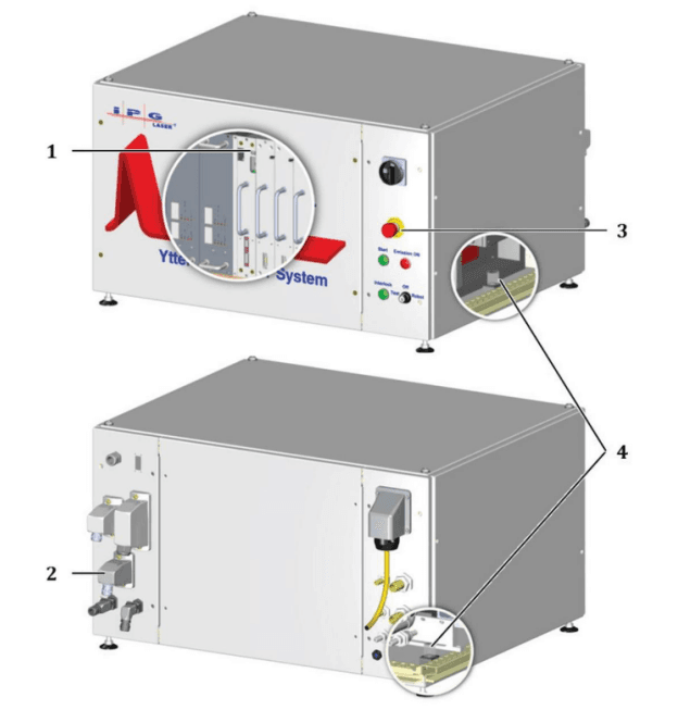
Figure 2-1: Safety equipment
| Item | Designation |
| 1 | Fiber break monitoring (sensors in the combiner module) |
| 2 | Safety interface (external E-Stop) |
| 3 | E-Stop button |
| 4 | Leakage sensors |
The status of the individual safety devices is indicated in theLaserNet software in the tabs Status and Alarms (see sections 11.8.1and 11.8.2).
The triggering of a safety device has the following effect:
(1) The corresponding safety circuit is opened.
(2) The main power supply is shut down.
(3) The laser emission is shut down.
Switching on
the main
power supply
In order to switch on the main power supply, all safety circuits must
be closed and the safety control of the laser must be reset.
⇒ Close all safety circuits.
The yellow light of the Interlock illuminated pushbutton on the frontside of the laser goes out once all safety circuits are closed.
The illuminated pushbutton lights up yellow when power is present.
If all safety circuits are closed, the safety control of the laser can bereset manually.
The following options are available to you for performing a manualreset (see section 7.3):
. LaserNet
. Start illuminated pushbutton. Safety interface
Another option for resetting the safety control exists via the bussystem, if present (see corresponding information in the suppliedtechnical data).
⇒ Use one of the options to reset the safety control and switch on the main power supply.
The green light of the Start illuminated pushbutton on the front side of the laser lights up as soon as the safety control of the laser has been reset and
activated.
Monitoring the
status
The status of the laser can be monitored via the safety interface.
When the main power supply is switched on, the contacts are closed.
They can be used, among other uses, to control external warning
lamps.
The signal for the status of the E-Stop button is connected to the safety interface (status of E-Stop button, 2-channel safety output)
and can be integrated into the safety circuit of the system owner.
2.10.1 E-Stop button
An E-Stop button is located on the front side of the laser. Pressing ofthe E Stop button leads to an immediate shutoff of the main power supply and thereby the laser emission.
After triggering of the E-Stopbutton, laser emission is no longer possible.
To switch the main power supply back on, the E-Stop button must be reset.
2.10.2 External safety interface
2-channel safety signal external E-Stop. If this input is not connected, no laser emission can be enabled.
. Safety characteristics according to EN 13849-1. Performance level d, category 3
. A safe emergency stop shutdown of the laser emission and can be achieved with a secure two-channel signal removal at this interface.
The system integrator can use this data for a safety subsystem within its overall safety chain (sensor systems – logic – actuator system).
The contact assignments are described in detail in the supplied technical data.
2.10.3 Fiber break monitoring
The feeding fiber of the laser is continuously monitored (electrical contact). In the event of a fault, the laser emission is switched off.
2.10.4 Leakage sensors
Leakage sensors are located on the bottom of the laser cabinet(inside). If water is present in the laser, this leads to an immediate shutoff of the main power supply and thereby the laser emission.
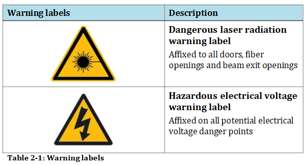
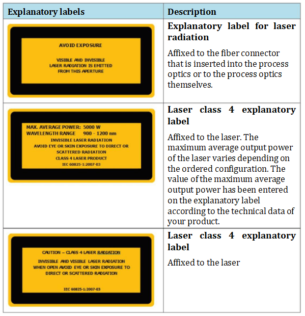
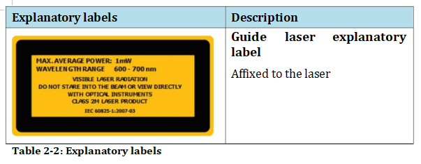
2.11 Safety labels
The explanatory and warning labels affixed to the laser are shown in this section.
2.12 Independent alteration or replacement parts procurement
Alteration or modifications to the product are only permitted withthe written approval of the manufacturer. Original spare parts andaccessories authorized by
the manufacturer serve to ensure safety.Failure to heed these instructions results in exclusion of all liability.
3 Device description
The CUT series of high power fiber laser described in this operatingmanual was developed particularly for cutting and welding applications on metals and metal alloys.
Depending on theconfiguration, the dimensions of the cabinet and the power of thelaser can vary (1.0 to 8.0 kW). However, the positions of the groupe delements and interfaces remains unchanged.
3.1 Overview
The following figure provides an overview of the most important external elements of the high power fiber laser, using the laser YLS-4000-CUT as example.
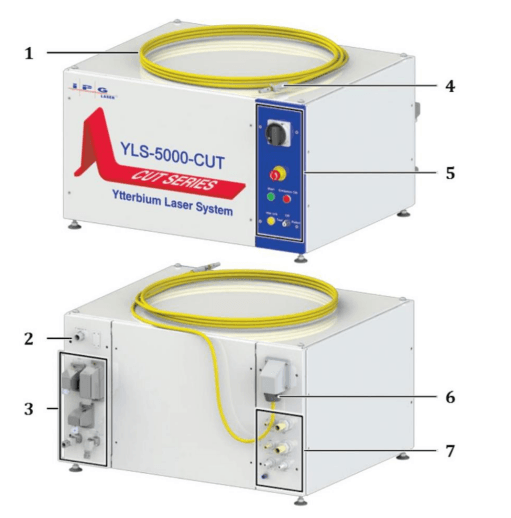
Figure 3-1: Overview of the laser
| Item | Designation | Description |
| 1 | Feeding fiber | Guides the laser beam to the process optics. |
| 2 | Cable gland / mains connection | The voltage supply cable runs through the cable gland to the connection point on the main switch. |
| 3 | Interfaces and mains connection | Communication and safety interfaces |
| 4 | Fiber connector | Connects the laser radiation to the process optics. |
| 5 | Operating elements | Elements for operation and monitoring of the laser |
| 6 | Feeding fiber outlet | Outlet of the feeding fiber |
| 7 | Connections | Water connections |
The operating elements of the laser are located on the right frontside. On the back side, the interfaces and cable gland for the supplyvoltage cable are on the
left; on the right are the connections and inthe upper right corner the outlet of the feeding fiber. The fiberconnector at the end of the feeding fiber is inserted
into the processoptics provided by the system owner.
3.1.1 Operating elements
The operating elements of the high power fiber laser YLS-6000-CTare described below. The number and arrangement of the operatingelements can vary based on the configuration of the laser. For more information about your product, see the supplied technical data.

Figure 3-2: Operating elements
| Item | Designation | Description |
| 1 | Start illuminated pushbutton | Pressing the start illuminated pushbutton switches the main power supply on. The illuminated pushbutton lights up green as soon as the main power supply is switched on. |
| 2 | Interlock illuminated pushbutton | The illuminated pushbutton lights up yellow as soon as the safety circuit is opened. You can test this lighting function by pressing the illuminated pushbutton. |
| 3 | Main switch | Disconnects the laser from the supply voltage. |
| 4 | E-Stop button | Pressing the E-Stop button in an emergency situation switches off the main power supply and the laser emission. |
| 5 | Illuminated pushbutton Emission ON | The illuminated pushbutton lights up red when the laser is emitted. You can test this lighting function by pressing the illuminated pushbutton. |
| 6 | Key switch | The operating modes TEST and ROBOT can be selected and the laser switched off (OFF) with this key switch. |
3.1.2 Interfaces and connections
On the back side of the laser, the interfaces are situated on the left(1), the connections are found in the lower area (2).
More information about your product can be found in the supplied technical data.
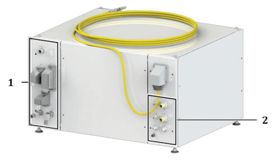
Figure 3-3 Interfaces
| Item | Designation |
| 1 | Interfaces |
| 2 | Connections |
3.1.3 Main components
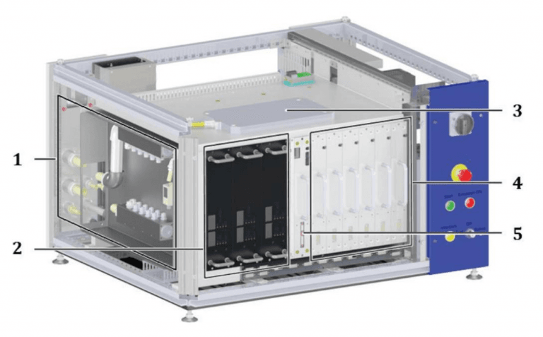
Figure 3-4: Laser layout
| Item | Designation | Description |
| 1 | Distributor and flow meters of the water system | The distributor distributes the cooling water among the existing cooling systems. The flow meters measure the flow rates of the individual cooling systems. |
| 2 | Main power supply | Generally consists of multiple individual power supplies in a quantity that depends on the laser power. Provides the necessary voltage and current intensity to the laser modules. |
| 3 | Splice box | Connects the fiber from the combiner module with the feeding fiber. |
| 4 | Laser module | Generates the laser radiation. |
| 5 | Combiner module | Combines the fibers of the individual laser modules into one fiber. |
The laser has a modular design. In the right area of the cabinet are the laser modules, the combiner module is situated to the left of this.
The main power supply and the distributors and flow meters of the water system are found in the left area of the cabinet.
The number oflaser modules and laser power supplies depends on the requiredlaser power and the respective configuration of the laser.
The splicebox is located above the laser modules and the main power supply.
3.1.4 Electrical mounting plate
The electrical mounting plate of the high power fiber laser YLS-3000-CUT is shown as an example in the following figure.
The components and their arrangement on the mounting plate can vary based on the configuration of the laser.
The exact layout of the mounting plate of your laser as well as theinformation about the components used can be found in the supplied circuit and layout diagram of the mounting plate.
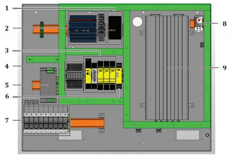
Figure 3-5 Electrical mounting plate
| Item | Designation |
| 1 | Miniature fuses |
| 2 | Terminal blocks |
| 3 | Safety control |
| 4 | Relay blocks |
| 5 | 24V power supply unit |
| 6 | Safety relay |
| 7 | Safety fuses |
| 8 | Temperature sensor |
| 9 | Electronic laser control |
3.2 Functional principle
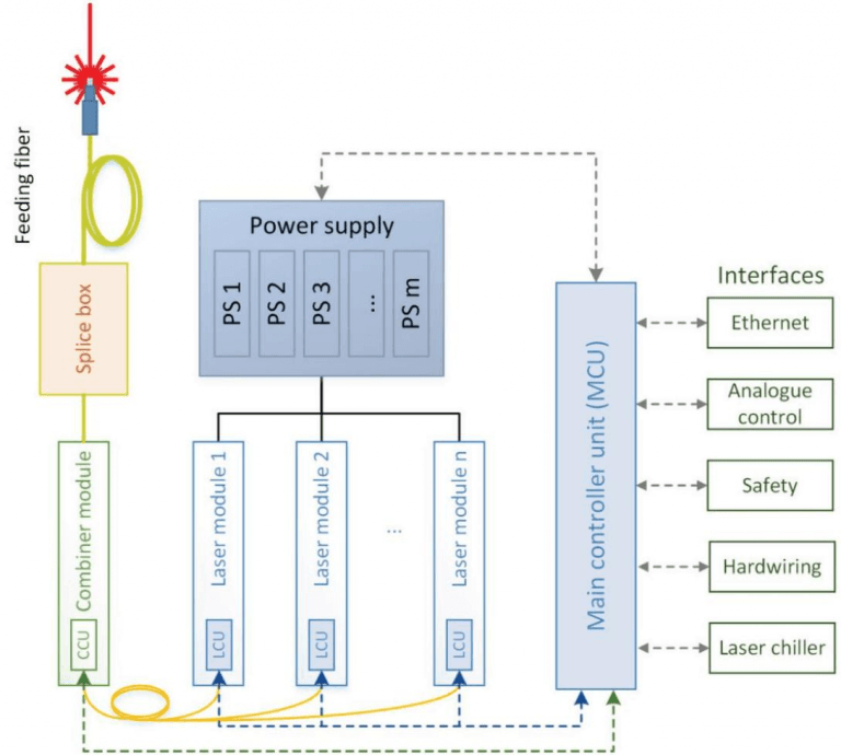
Figure 3-6: Functional principle of the fiber laser
| Designation | Description |
| CCU (combiner control unit) | Combiner module control |
| Combiner module | Combiner module |
| Splice box | Splice box |
| Main Controller Unit (MCU) | Laser control |
| Laser module 1 to n | Laser module 1 to n |
| LCU (laser module control unit) | Laser module control |
| Interfaces | Interfaces |
| Ethernet | Ethernet |
| Analogue control | Analog control |
| Safety | Safety interface |
| Hardwiring | Hardwiring |
| Laser chiller | Laser chiller |
| Power supply | Power supplies for laser modules as well as the laser and chiller control |
| PS 1 to m | Individual power supplies from 1 to m |
The laser radiation is generated in these laser modules, which areintegrated in the laser. Every laser module can be understood as anindependent laser.
Depending on the type, a laser module has anoutput power between 700 and 1800 W. The number of modules is determined by the nominal output power of the laser.
The laser modules require direct current to generate the laserradiation.
The direct current is generated by the main power supply,which is integrated into the laser.
The main power supply generally consists of multiple individual power supplies in a quantity that depends on the laser power.
The radiation generated in the laser modules is guided by the associated fibers into the combiner module, where they arecombined into a single fiber.
The fiber from the combiner module isspliced to the feeding fiber in the splice box; the laser radiation is fedhere into the feeding fiber.
Via the feeding fiber, the laser radiationenters the external process optics, which are specific to the system owner and focus the laser radiation on the material processing point.
Depending on the selected configuration, the feeding fibers may differ in core diameter and length.
4 Delivery and transport
In the event of improper handling during transport, damage to the product can occur that could endanger persons.
⇒ Wear the required personal protective gear during loading and unloading of the product and during transport.
4.1 Scope of delivery
The delivery consists of:
. Laser YLS-XXXX-CT
. CD with the software LaserNet and operating manual for the laser
. Accessories (see supplied accessories list)
4.2 Delivery and transport
The product is delivered in packaging that offers maximum protection.
The packaging is equipped with a shock and tip watch that warns in event of improper handling.
If the packaging shows signs of external damage or the shock and tip monitoring was activated, immediately inform the transport company and your representative at IPG Laser GmbH.

Not tipped

Tipping angle

Transport without shock Transport with shock
Figure 4-1: Transport monitoring

4.2.1 Unloading
The product is delivered in a wooden transport crate. The product and the accessories are delivered on transport pallets.
The system owner is responsible for the unloading of the components and their transport to the final installation site of the product.

4.2.2 Unpacking the product
⇒ Remove the product and the supplied accessories from the packaging.
⇒ Save the packaging material and the inserts in case transport or storage are required in the future.
Completeness
⇒ Check the delivery documents to verify that all parts are
present and complete. If parts are missing or the product is
damaged, immediately notify IPG Laser GmbH.
Packaging
material
⇒ Save the packaging material at least until any irregularities are
resolved.
4.2.3 Transport to the installation site
Transport with
a forklift
⇒ Always use a pallet when transporting with a forklift.
⇒ Ensure that the product is sufficiently secured during
transport.

Figure 4-2: Transport with pallet
Transport with
crane
Eye bolts are affixed on the top side of the laser cabinet; these can be
used to lift the product out of the transport packaging and to
transport it to the installation site using a suitable lifting device.
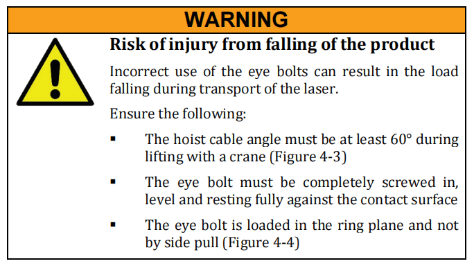
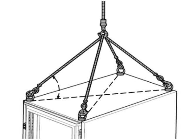
Figure 4-3: Hoist cable angle during crane transport
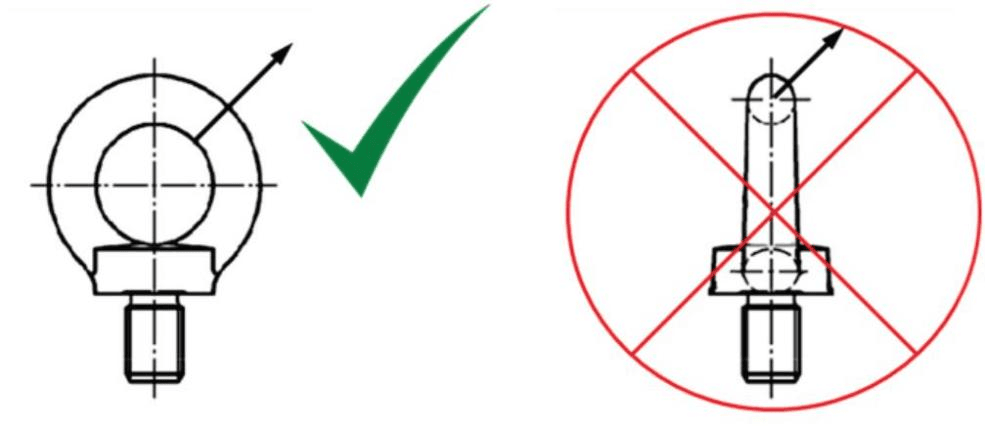
Figure 4-4: Tensile load on the eye bolt
Transport on
casters
Products equipped with robust casters can be moved to their
installation site over short distances without additional aids.
⇒ Turn the locking mechanism (1) on the casters of the product
up to be able to move the product (Figure 4-5).
only on smooth, level floors.
⇒ Install the product on a level surface.
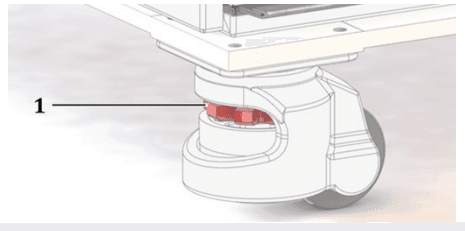
Figure 4-5: Caster with locking mechanism
5 Assembly and installation


5.1 Space requirements and room conditions
Installation
The following points must be complied with before installation of the
product.
⇒ Select the installation position such that access to the product
from all sides is guaranteed.
o A minimum distance of 1 m must be maintained on all
sides.
⇒ Note the weight of the product as well as the temperature and
humidity limits when selecting the installation site.
5.2 Supply connections
The product requires a supply voltage as well as cooling waterconnection.
⇒ Make sure that all required supply connections are available and usable.
5.2.1 Supply voltage
⇒ Connect the product to a 3 x 400 VAC or 3 x 460 VAC supply voltage.
The precise information on the supply voltage can be found in the supplied technical data.
The connection has four poles (L1, L2, L3 and PE).
| Laser | Design | Unit | Max. deviation |
| Operating voltage | 400 / 3P + PE or 460 / 3P + PE | VAC | ± 10% |
| Frequency | 50 (400 VAC ) 60 (460 VAC) | Hz | ± 1% |
Table 5-1: Required supply voltage
Electrical
connection
The electrical connection takes place in the laser (feeding through
screw connection on back side). The distribution to the control and
the laser takes place internally.
5.2.2 Cooling water supply
Tap water
The tap water serves for cooling of the laser modules. The following
requirements must be met:
. The water hardness may not exceed 0.25 dH.
. The electrical conductivity should not exceed 50 µS/cm.
DI water
The partially deionized water (hereafter referred to as DI water)
serves for cooling the optical elements. Depending on the product
configuration, it can also be used for cooling of the laser modules.
The DI water should satisfy the following specifications:
. The water hardness may not exceed 0.25 dH.
. If possible, the electrical conductivity of the water should be 35 to 45 µS/cm. In the event of a higher conductivity, a DI
cartridge built into the IPG laser chiller deionizes the water
until the required value is reached; however, this can take some time.
5.4 Running lines and fibers
5.3 Setting up the laser
⇒ If the product is not located at its final installation site, follow the instructions given in section 4.2.3 for setting up the product at its final location.
Unpacking the
fiber
1.Remove the plastic bag at the end of the fiber.
2.Remove the cable ties or tape with which the fiber is fastened
to the product or the transport box.
Running the
fiber
3.Take the fiber connector in your hand and roll out the fiber
without twisting.
4. Run the fiber in a suitable cable channel.
5.5 Connecting the laser
Protection
class

⇒ Use only the provided electrical plug connectors.
⇒ Close all unused interfaces with the provided protective caps.
⇒ Consult with IPG Laser GmbH before manufacturing deviating supply lines (in particular interface cables).
⇒ Do not add any additional openings to the cabinets.
⇒ Carefully close the cabinet of electrical or electronic components after installation.
5.5.1 Connecting the water supply

. Work on the cooling water distribution may only be performed by IPG service personnel or specially trained experts.
. An insufficient supply of cooling water can lead to damage to the laser or the optics.
. It is not permitted to create bridges, bypasses, etc., since these represent manipulations of the laser cooling system.
The product is a model without integrated water cooling; the cooling of the laser and optics circuits must take place by means of an external cooling system.
The cooling water distribution to the laserand optics always takes place inside the product.
The water connections (tap water for the laser circuit, DI water for the opticscircuits) are located on the back side of the product.
The water connections are shown in the following figure.
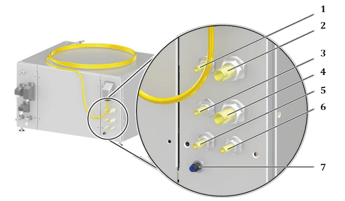
Figure 5-1: Water connections on the laser
| Item | Designation |
| 1 | Process optics (external optics) return flow |
| 2 | Laser circuit feed pipe |
| 3 | Process optics (external optics) feed pipe |
| 4 | Laser circuit return flow |
| 5 | DI water feed pipe |
| 6 | DI water return flow |
Connecting the
water supply
1. Connect the hoses of the tap water supply to the tap water
connections according to the designation. Note the direction of
water flow.
2. Connect the hoses of the DI water supply to the DI water
connections according to the designation. Note the direction of
water flow.
3. Connect the water connections of the external optics according
to the designation.
Connection
cooling water
hoses to the
process optics
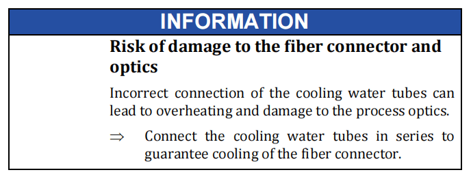
After the fiber connector, the individual components of the optics can also be connected in parallel.

Figure 5-2: Water connection on the fiber connector
5.5.2 Connecting the supply voltage

| 1. | Remove the screws of the right side panel with a Torx T30 screwdriver. | ||
| 2. | Remove the right side panel of the laser to access the mounting plate. | ||
| 3. | Run the supply cable through the cable gland (2) on the back side of the laser. | ||

Figure 5-3: Supply voltage connection
- Connect the protectiveearth conductor PE (green/yellow).
- Check the rotary field (clockwise) of the supply voltage.
| 6. | Connect the three wires of the supply cable to the connections of the main switch QCE (1). The connections are located on the electrical mounting plate within the laser cabinet. | |||
| 7. | Secure the supply cable against strain with the screw connection (3). | |||
5.5.3 Connecting the external interfaces
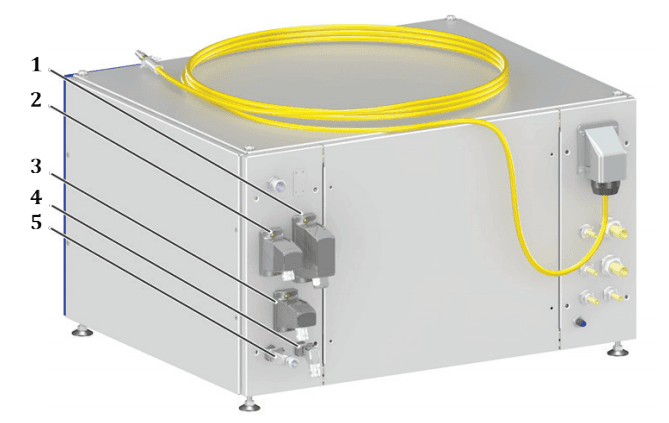
Figure 5-4: External laser interfaces
| Item | Designation |
| 1 | Hardwiring |
| 2 | Interface to the laser chiller |
| 3 | Safety interface |
| 4 | Ethernet interface |
| 5 | Analog interface |
⇒ Connect the interface cables according to the supplied technical data.
⇒ Ensure that the locks of the plug connectors snap into place.
5.5.4 Connecting the fiber connector to the process optics
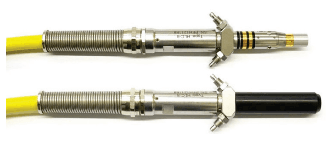
Figure 5-5: Fiber connector without (top) and with (bottom) protective cap
Before inserting the fiber connector into the process optics, the quartz-block end face must be checked for soiling and cleaned, if necessary.
To do this, proceed as described in section 8.1.1. This section also contains instructions on how to correctly connect the fiber connector to the optics.
5.6 Installing the software
The software LaserNet is included with the product. With this software, you can monitor the laser and its auxiliary components as well as operate them, if necessary.
Fast Ethernet 100 Mbit/s is used as the interface between the computer and the laser.
Information about system requirements and software installation can be found in section 11.
6 Acceptance and commissioning
6.1 Visual inspection
The visual inspection offers an initial overview of the condition of theinstallation.
⇒ Ensure the following:
. A space of 1 m must be maintained on all sides of the product.
. The casters of the product must be locked (if present).
. All plug connectors must be locked or screwed onto the product.
. The laser cabinet and the fiber must not exhibit any visible damage.
6.2 Work to be performed before commissioning
⇒ Perform all acceptance tests in the supplied commissioning report.
The product is ready for production operation after successful completion of the acceptance tests.
6.3 Transfer to operation
The responsible service engineer of the competent IPG servicedepartment signs the commissioning report.
The authorized representative(s) of the system owner checks the commissioning report for accuracy and completeness and signs it.
After signing of the commissioning report, the laser is transferred toproduction operations to be commissioned.
6.4 Recommissioning
After a prolonged shutdown, the product must be completely inspected before being commissioned again.
⇒ Carry out the entire commissioning procedure according to section 6.2.
7 Operation
7.1 Operating modes
The laser can be operated in two operating modes.
TEST
Operating mode TEST is for manual operation of the laser. In TEST
mode, the laser can be controlled via the LaserNet software.
ROBOT
Operating mode ROBOT is for automatic operation of the laser.
ROBOT mode is the standard operating mode for production. The
laser is controlled via the hardwiring interface. The LaserNet
software is used for monitoring the laser operation.
7.2 Switching on/off
Switching on
1. Make sure that all supply lines are connected and available.
2. Water
3. Voltage supply
4. Switch on the laser with the main switch.
5. Switch on the external laser chiller.
6.Turn the key switch on the front side of the laser to TEST or
ROBOT.
Switching off
After completing the work, switch off the laser according to the following procedure.
- Turn the key switch on the front side of the laser to OFF.
- Switch off the external laser chiller.
- Switch off the laser with the main switch.
7.3 Switching on the main power supply
Various options for switching on the main power supply are described below.
Start
illuminated
pushbutton
The Start illuminated pushbutton is located on the front side of the
laser (see section 3.1.1). If this is pressed, the main power supply
turns on as long as the internal and external safety circuits are
closed. When the main power supply is switched on, the Start
illuminated pushbutton lights up green.
Safety
interface
The safety interface is located on the back side of the laser. Closing of
the potential-free contacts at this safety interfaces switches on the
main power supply (see also section 7.4.3). To switch the main
power supply back on again, such as after a fault, the contacts must
first be opened (for the pin assignment of the safety interface, see the
supplied technical data).
LaserNet
software
In TEST mode (manual operation), the main power supply can be
switched on via the LaserNet software.
Hardwiring
interface
In ROBOT mode, the main power supply can be switched on via the
hardwiring interface (control supplied by the system owner) (see the
supplied technical data).
7.4 TEST mode
In TEST mode, you require an external computer on which theLaserNet software is installed in order to control the laser.
The communication between the computer and laser takes place bymeans of an Ethernet interface (see supplied technical data).
The LaserNet software is described in detail in section 11.
Establishing a
connection to
LaserNet
1.Follow the steps described in section 7.2 to switch on the laser
in TEST mode.
2.Establish a connection to the laser, if this has not already been
done (see section 11.3).
3.Start the LaserNet software (see section 11.4).
4. Open the Control tab.
The buttons for controlling the laser are found here (Figure 7-1). The
buttons (5) to (9) always indicate the current switching state.
Pressing the buttons causes a change to the operating state of the
laser.
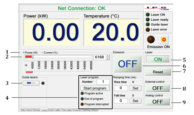
Figure 7-1: Control tab
Checking the
beam path
After maintenance work and a prolonged shutdown of the laser, the
beam path must be checked with the help of the guide laser.
5. Click on the guide laser button (3).
The guide laser switches on. The LED indicator next to the button is activated. On the Status tab, the status LED indicator “Guide laser ON”lights up green.
6.Check whether the guide laser is visible at the exit point of the process optics.
If the laser beam is visible at the exit point of the process optics, the beam path is OK.
Switching on
the main
power supply
If the beam path is OK, you can switched on the main power supply.
If not, ensure that the beam path is clear before switching on the
main power supply.
- Clickon the button Laser OFF (5).
The main power supply switches on. The status of the button changes to ON. On the Status tab, the status LED indicator “Main power supply ON” lights up.
The lower segments of the laser warning lights turn on with steady light. If no alarms are present, the laser switches to the Laserready state.
After switching on the main power supply, you can continue to work with or without the laser program.
7.4.1 Working without the laser program
- Make certain that the mainpower supply is switched on.
Setting the
laser power
2. In the option fields (1), select whether the laser light should be
indicated in percent of the pump current or directly as power
in watts.
3. Set the laser power with the slider (2) or enter a value directly
into the input field to the right of the slider.
Switching on
the laser
emission
4. Click on the button Emission OFF (6).
As soon as the laser is emitted, the status messages Emission enabled
and Emission ON become active. The upper segments of the laser
warning lights on the laser cabinet begin to blink. The emitted laser
power is indicated in the power output indicator field (kW). The laser
power can be changed at any time using the slider.
Switching off
the laser
emission
5. Click on the button Emission ON (6) to switch off the emission.
Switching off
the main
power supply
6. Click on the button Laser ON (5) to switch off the main power
supply.
The status indicators Laser ON and Laser ready are deactivated.
7.4.2 Working with the laser program
- Make certain that the mainpower supply is switched on.
- Select the program number (5) of the laser program you would like to work with. Information on program creation can be found in section 11.9.Clickon the button Start program (4).
- During execution of the program, the button Start program changesto STOP. In addition, the status message Program active is activated.After the end of the laser program, the status End of program isactivated. The status message Program active is deactivated.
An interruption during the execution of the laser program is indicated by the fault Program interrupted. The reason for the interruption of the laser program is displayed on the Events tab.
You can also interrupt a laser program by clicking on the button STOP. In this case, the fault message Program interrupted is output.
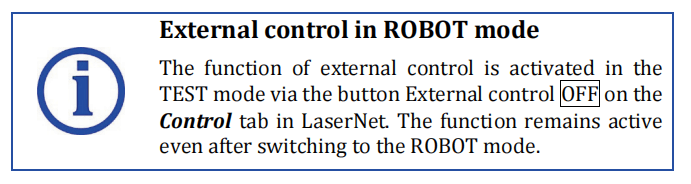
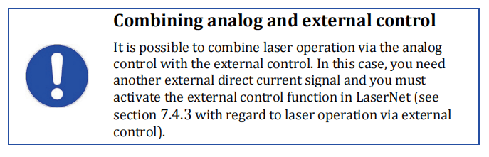
7.4.3 External control
The external control can be configured as another condition for switching on the laser radiation in the laser.
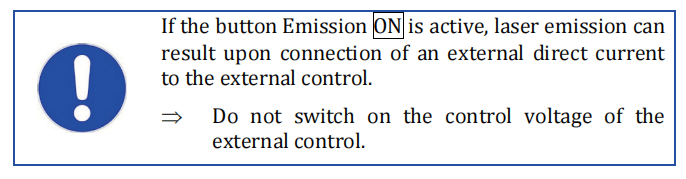
For switching the laser emission on and off via the external control, the signal Emission ON at the safety interface is used.
HIGH signal (+4 … 30 VDAC) – Emission ON LOW signal (-3 … + 2 VDC) – Emission OFF
This signal can be used for modulation of the laser radiation. This requires a signal generator that outputs a square wave.
The laser radiation can be modulated with a frequency up to a maximum of5,000 Hz.
For more information about the safety interface, see the supplied technical data.

To operate the laser via the external control, do as follows:
1. Establish a connection to LaserNet, if this has not already been
done (see section 7.4, instruction Establishing a connection to
LaserNet).
2. Connect the external control to the safety interface (for the pin
assignment of the safety interface, see the supplied technical
data).
3. Open the Control tab (see Figure 7-1).
Activating the
external
control
4. Click on the button External control OFF (8).
The button then changes its status to ON. The external control is
activated.
5. Click on the button Laser OFF.
The button then changes its status to ON. The main power supply switches on.
6. Configure the laser power (see section 7.4, instruction Setting
the laser power).
7. Click on the button Emission OFF.
8. Set the signal Emission ON of the external control to HIGH.
The laser radiation is enabled. The laser emits the preselected laser
power. You can change the power at any time using the slider (1) or
directly entering a new value.
Deactivating
the external
control
9.Set the signal Emission ON of the external control to LOW.
10.Click on the button Emission ON.
The laser emission stops.
11. Click on the button Laser ON.
The main power supply switches off.
7.4.4 Analog control
With the analog control function, you can define the preselected power via the analog interface.
The function is also available inROBOT mode (see interface description in the supplied technical data).
To use the analog control function, a direct current signal of 0…10VDC must be present at the analog interface (see supplied technical data).
This signal can be used for modulation of the laser power. This requires a signal generator.
To define the power preselection via the analog interface, do as follows:
1. Establish a connection to LaserNet, if this has not already been
done (see section 7.4, instruction Establishing a connection to
LaserNet).
2. Open the Control tab (see Figure 7-1).
Activating the
analog control
3. Click on the button Analog control OFF (9).
The button then changes its status to ON. The analog control is
activated.
4. Click on the button Laser OFF.
The button then changes its status to ON. The main power supply switches on.
5. Select the laser output power via the analog interface (see
supplied technical data).
An input voltage of 0 VDC corresponds to a laser power of 0 W, 10
VDC corresponds to the nominal output power. The laser power can
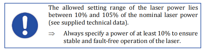
be set via the signal Analog control. The exact setting range of the
laser power can be found in the supplied technical data.
6. Click on the button Emission OFF.
The button then changes its state to ON. The laser radiation is enabled.
The laser emits the preselected laser power. You can change the power
at any time via the connected input voltage of the analog interface.
7. Click on the button Emission ON.
The laser emission stops.
8. Click on the button Laser ON.
The main power supply switches off.
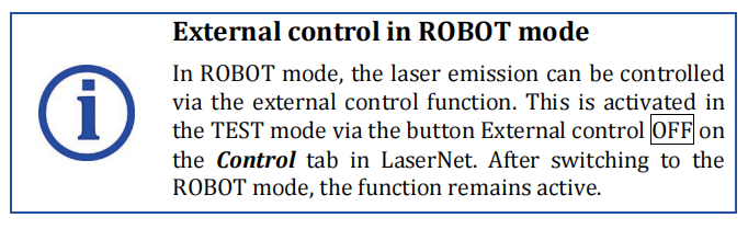
7.5 ROBOT mode
In the ROBOT mode, the laser is controlled via the hardwiring interface or the external fieldbus interface, if present.
The communication between the control unit of the system owner(robot) and the laser takes place according to the interface description and/or the installed fieldbus protocol (see supplied technical data).
In order that you can generate output signals via the hardwiring interface, you must apply supply voltage between the corresponding contacts (see supplied technical data).
HIGH signal +4…30 VDC
LOW signal –3 V…+2 VDC
1. Follow the steps described in section 7.2 to switch on the laser
in ROBOT mode.
2. Establish a connection to the laser, if this has not already been
done (see section 11.3).
3. Start the LaserNet software (see section 11.4).
The LaserNet software is used for monitoring the laser operation. All
LaserNet buttons, except for the button Reset, are activated. If
required, the button Reset can also be deactivated.
Complete information about the LaserNet software can be found in
the section 11.
Checking the
beam path
After maintenance work and a prolonged shutdown of the laser, the
beam path must be checked with the help of the guide laser.
4. Switch on the guide laser with the corresponding signal via the
hardwiring interface or the fieldbus interface (for interface
description and the fieldbus protocol, see the supplied
technical data).
The guide laser switches on. The corresponding signal is sent back from
the laser to the robot as confirmation.
5. Check whether the guide laser is visible at the exit point of the
process optics.
If the laser beam is visible at the exit point of the process optics, the
beam path is OK.
Laser program
To be able to enable laser radiation in ROBOT mode, a laser program
must be set. You can set a laser program you created yourself
(program number 1 … 50) (for interface description and the fieldbus
protocol, see the supplied technical data) or work with laser
program 0. Laser program 0 is automatically active as soon as you
switch on the laser emission without having set a custom laser
program. In this case, the laser is emitted until the laser emission is
switched off again via the corresponding signal.
⇒ Start the laser program according to the interface description
or the installed fieldbus protocol.
General
program
sequence
A typical program sequence is described below. The sequence can
vary depending on the interface modifications specific to the system
owner or the installed fieldbus protocol.
1. The input signal Request laser is sent by the robot to the laser.
Without this signal, all other input signals that may be set will
be ignored.
As an output from the laser, the signal Laser assigned is set.
2. The input signal Laser on switches on the main power supply.
As an output signal, Laser ON is sent when the main power supply has been successfully switched on and reached its nominal output voltage.
If no faults are active, the laser outputs the signal Laser ready.
3. The input signal Program number selects a laser program.
As an output signal, Program number is sent as confirmation.
4. The input signal Program start enables the laser emission.
If no program number is set, the laser operates with program
number 0. In this case, the output power must be set via LaserNet or
an external interface (analog interface or fieldbus). The emission
remains enabled as long as the signal Program start is set or until the
signal Program stop is sent. As long as a program is active, the laser sends the output signal Program active. When a program is finished,
the laser sends the output signal Program ended. If a program was
interrupted unexpectedly by a fault, the laser sends the output signal
Program interrupted.
Program
sequence –
example
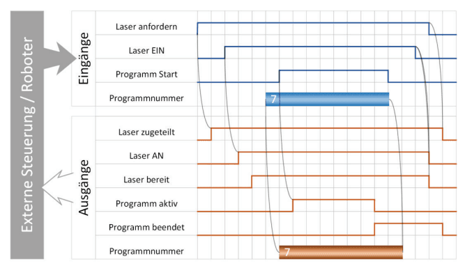
Figure 7-2: Program sequence – example
| Externe Steuerung / Roboter | External control / robot |
| Eingänge | Inputs |
| Laser anfordern | Request laser |
| Laser EIN | Laser ON |
| Programm Start | Program start |
| Programmnummer | Program number |
| Ausgänge | Outputs |
| Laser zugeteilt | Laser assigned |
| Laser AN | Laser ON |
| Laser bereit | Laser ready |
| Programm aktiv | Program active |
| Programm beendet | End of program |
8 Maintenance
⇒ Immediately after finishing the maintenance work, restore or activate all safety and protective equipment.
⇒ Check the correct connection of all safety-related components.
IPG Laser GmbH recommends that the maintenance work listed below be performed at the specified intervals.
8.1 Maintenance work
8.1.1 Clean fiber connectors
The fiber connector has to be cleaned before inserting the fiber(installation, optics replacement).
Notes about
cleaning
⇒ Only use the cleaning materials described in this operating
manual.
⇒ Only follow the cleaning procedure described in this operating manual.
⇒ Never touch the quartz-block end face or the glass surface of the screwable protective sleeve with your fingers.

Required
materials
You need the following materials for the cleaning:
. Lint-free cleaning swabs
. Isopropanol (anhydrous)
. Acetone (anhydrous)
. Compressed air (oil-free, anhydrous)
. Microscope, IPG model with light source (Figure 8-2)
The cleaning swabs are included in the scope of delivery. The
microscope and compressed air are included with the order.
Preparation
1.Ensure a clean working place close to the process optics and
the laser. Then minimize the risk of a re-contamination of the
fiber connector after the cleaning process.
2. Keep a clean protective cap available for the process optics.
3. Remove any impurities within the protective cap with
compressed air as a precaution before use.
4. After cleaning, place the protective cap on a clean storage
surface with the open side down.
5. Place the microscope on a level surface close to the optics to
ensure a secure base of the microscope.
6. Use a damp cloth to remove coarse dirt from the fiber
connector and the optics near the fiber connector.
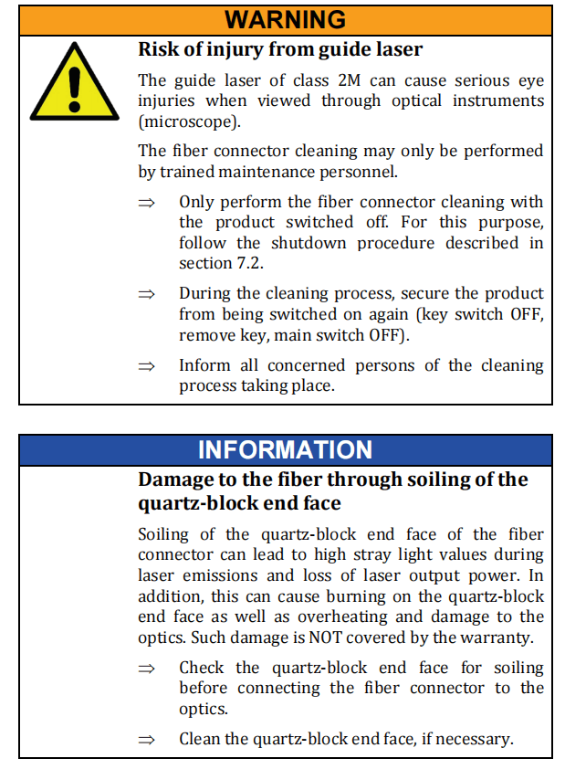
7. Disconnect the fiber connector from the optics. To do this, turn
the bayonet mount counterclockwise (1) and pull out the fiber
connector (2).
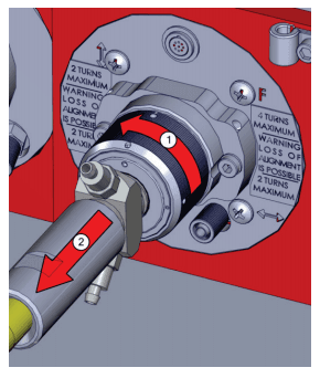
Figure 8-1 Disconnecting the fiber connector from the optics
8. Immediately seal the optics with the cleaned protective cap.
9. Place the fiber connector in the holder on the microscope
(Figure 8-2).
10. Switch the microscope’s light source on and point this towards
the surface to be cleaned.
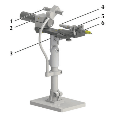
Figure 8-2: Microscope with fiber connector
| Item | Designation |
| 1 | Movable light source |
| 2 | Microscope |
| 3 | Pan head |
| 4 | Quartz block |
| 5 | Mount for the fiber connector |
| 6 | Fiber connector |
Individual cleaning steps differ depending on the chosen fiber connector option (Figure 8- 3).For fiber connectors with a protective conduit, the quartz-block end face is cleaned. For fiber connectors with a protective glass, the protective glass is only cleaned if the quartz-block end face is free of impurities. For persistent dirtaccumulation, the protective glass may be replaced with newprotective glass.
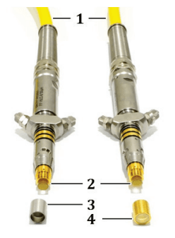
Figure 8-3: Fiber connector with accessories
| Item | Designation |
| 1 | Process fiber |
| 2 | Quartz block |
| 3 | Protective conduit |
| 4 | Protective glass |
Cleaning

Optional protective conduit
1. Remove the screwed on protective conduit.
2. Adjust the focus of the microscope to the quartz-block end face.
3. Check the quartz-block end face for impurities (e.g. dark
points). If you find impurities on the quartz-block end face,
perform the following steps.
4. Remove a cleaning swab from the package without touching
the wadding of the stick.
5. Moisten the cleaning swab with a drop of isopropanol.
6. Shake off excess isopropanol from the cleaning swab.
7. Look through the microscope and swipe with a light pressure
over the quartz-block end face of the fiber connector.

Figure 8-4: Cleaning the quartz-block end face
8. After 20 seconds at most, replace the cleaning stick if the
cleaning is to last longer.
The cleaning can be interrupted at any time if the cleaning result is
satisfactory.
9. Clean the protective conduit with compressed air outside of the
cleaning station and screw this back onto the fiber connector
once the cleaning of the quartz-block end face is completed. Do
not touch the quartz-block end face in the process.
10. Check the quartz-block end face again for impurities. If
necessary, repeat the cleaning process.
11. If the quartz-block end face is clean, remove the fiber connector
from the microscope and take this to the optics immediately.
Ensure that the quartz-block end face is facing down in the
process.
12. Remove the protective cap from the optics.
13. Carefully insert the cleaned fiber connector into the optics
immediately. When doing so, line up the red dots on the fiber connector (a) and the optics (b) with each other and push the
fiber connector carefully into the optics until the stop (Figure
8-5).
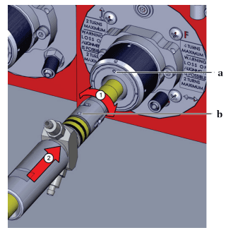
Figure 8-5: Connecting the fiber connector
14. Rotate the large pin behind the bayonet mount clockwise until
it clicks into place (3).
15. Rotate the grooved bayonet mount clockwise (4) by hand until
it is tight in order to secure the fiber connector.

Figure 8-6: Securing the fiber connector
Protective glass option
1. Adjust the focus of the microscope to the quartz-block end face
(third focal level).
2. If there are dirt deposits on the quartz-block end face, remove
the screwed on protective glass and follow the cleaning steps
described under the protective conduit option.
3. If the quartz-block end face does not exhibit any impurities,
adjust the microscope’s focus to the protective glass surface
(first focal level).
4. If the protective glass is dirty, perform the cleaning similar to
the cleaning procedure described under the protective conduit
option.
5. Alternatively, replace the dirty protective glass for a clean
protective glass. In doing so, ensure that no dirt deposits are
located on the quartz-block end face. Do not touch the new
protective glass with your fingers. Use the white protective
packaging in which the protective glass was delivered in order
to screw the new protective glass onto the fiber connector.
8.1.2 Measuring the laser output power
| Test point | Laser output power |
| Test method | Performance measurement |
| Time interval | Annually |
| Time duration | 2 hours / depending on the laser design |
| Tools | Performance measuring device |
| Description | ⇒ Contact the competent IPG Service department in advance of the performance measurement to clarify the exact procedure. |
8.1.3 Measuring the beam quality
| Test point | Beam quality |
| Test method | Measurement |
| Time interval | Annually |
| Time duration | 2 hours |
| Tools | Beam quality measuring device |
| Description | ⇒ Contact the competent IPG Service department in advance of the performance measurement to clarify the exact procedure. |
8.2 Replacement and repair work
8.2.1 Replacing a laser module
| Test point | Laser module |
| Test method | Performance measurement |
| Time interval | In the event of a fault |
| Time duration | ~ 3 hours |
| Performance | IPG service |
| Contact | See section 9.4 |
8.2.2 Replacing the feeding fiber
| Test point | Feeding fiber |
| Test method | Measurement of the transmission and beam quality |
| Time interval | In the event of a fault |
| Time duration | ~ 5 hours |
| Performance | IPG service |
| Contact | See section 9.4 |
8.3 Water system (IPG chiller)
Information for maintenance of the water system can be found in the operating manual of the laser chiller.
9 Messages and troubleshooting
9.1 Information about message displays
All warnings and alarms that occur during laser operation aredisplayed in the LaserNet software in the tabs Warnings and Alarms(sections 11.8.2 and 11.8.3) as active LED indicators.
In the event of a warning, an LED indicator in the Warnings tab lights up. The laser remains in operation. If an alarm is present, the LED indicator Laser error in the status indication area (see Figure 11-11) lights up red and the green LED indicator Laser ready goes out. Any laser emission is stopped immediately. The corresponding LED for the alarm lights up in the Alarms tab.
⇒ Detailed information on the individual messages can be found in the Events tab (section 11.8.5).
To put the laser back into operation after eliminating the problem, the alarms must be reset. For some messages, this takes place automatically; for others, you must click the Reset button in theControl tab (section 11.8.4).
9.2 Status messages, warning messages and alarms
Information about the status, warning and fault messages is collected in Annex A.
9.3 Troubleshooting
Detailed information on troubleshooting can be found in Annex A.
9.4 Manufacturer service
9.4.1 Behavior in the event of malfunctions
For the most comprehensive possible description of the problem, were commend downloading an events file as a .txt file and an overview of the configuration via LaserNet and sending this by email to the competent IPG service department.
. Log files (section 9.4.2)
. Events file as .txt file (section 9.4.3)
. Overview of the configuration (section 9.4.4)
9.4.2 Downloading the log files via LaserNet
The log files are automatically generated in the laser and can bedownloaded via the LaserNet software.
They contain informationabout the laser, its operating parameters, all important events and any alarms.
The laser log file Laser.dat also contains information about the laser chiller. Follow to the following steps to download a log file:
- Start the LaserNet software.
- Make certain that there is a network connection to the laser.
- Select the Logfiles tab.
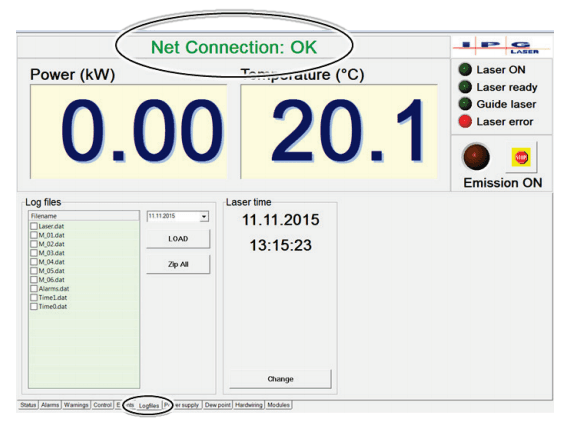
Figure 9-1: Downloading log files
You have two options to save the log files:
. Individual log files from a certain day via the Load button
. All log files over a certain time period via the Zip All button
Load
1. Select the date on which the problem occurred. If the date is
not known, you can use the Events tab to find this out.
In the File name field, a list appears with the existing log files from the
selected date. If on the selected day the laser was not switched on, no
log files were generated for the date and the File name field remains
empty.
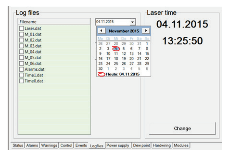
Figure 9-2: Select date
2. Using ConfigurationLaserNet Settings Paths… select the folder
in which you want to store the log files. As a standard, the
folder C:UserMy DocumentsIPG Laser GmbH the default.

Figure 9-3: Storage path for log files
3. Select the log files that you would like to download. You have to
options to do this:
o Select the files individually with the left mouse button.
o Use the right mouse button to click on the log files and in
the window that appears select the Select all option with
the left mouse button.
4. Click on Load to download the file in the pre-specified folder.
LaserNet creates a new folder in the pre-set folder and names this
according to the date from which the log files originate (e.g.
24.07.2015). The selected files are stored in this folder.

Figure 9-4: Select log file
Zip All
1. Click on the Zip All button.
The dialog window Zip All will appear.

Figure 9-5 Dialog window Zip All
2. Specify the desired time period in the combination fields From
and To.
3. Using the … button, select the folder in which you want to store
the log files.
4. Click on the OK button.
All log files from the selected time period will be stored in the selected
folder.
⇒ Send the downloaded log files by e-mail to the competent IPG
service department (see paragraph 9.4.1).
9.4.3 Downloading the events file via LaserNet
In the Events tab, all events reported during the laser operation arelogged and listed in chronological order.
These event messages can supply useful information about the cause of the fault and should be sent by email together with the log files to the competent IPG service department in the event of a fault.
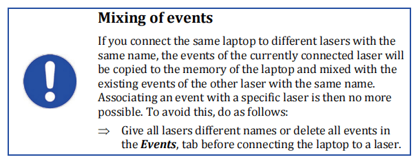
To download the events in the form of a .txt file, do as follows:
1. Start the LaserNet software.
2. Make certain that there is a network connection to the laser.
3. Select the Events tab.
4. Right-click on one of the event messages and use the left mouse
button to select the option Save events to a file.
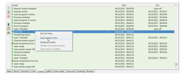
Figure 9-6 Saving events to a .txt file
5. Select the save location and click on Save.
The events file is saved. It contains the serial number of the laser in its
name.
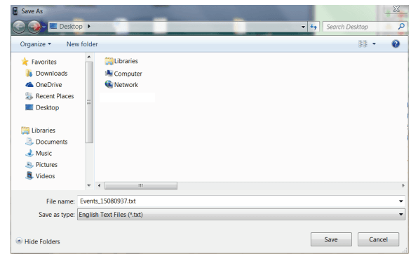
Figure 9-7 Selecting the save location
6. Send the downloaded file by e-mail to the competent IPG
service department (see paragraph 9.4.1).
9.4.4 Downloading the configuration overview via LaserNet
The configuration overview contains information about the laser, itsconfiguration, the configured parameters and the firmware statusesof built-in components.
Follow to the following steps to download the configurationoverview file:
- Start the LaserNet software.
- Make certain that there is a network connection to the laser.
- Select under ConfigurationLaser the submenu Configuration Overview.
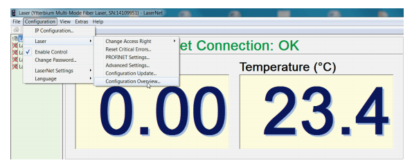
Figure 9-8: Opening the configuration overview
A new window appears with the configuration overview.
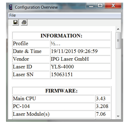
Figure 9-9: Configuration overview
4. Click on the diskette symbol in the upper left corner.
A Save as window appears
5. Select the save location and click on Save.
The configuration file is saved.
6. Send the downloaded file by e-mail to the competent IPG
service department (see paragraph 9.4.1).
9.4.5 Updating the firmware and laser configuration
Some faults may require a firmware update. This can be done with the help of an HPLP file. The file will be sent to you by email from thecompetent IPG service department.
Contact the competent IPGservice department and describe the problem.
In order for theproblem to be solved more quickly, we recommend creating a log filewith LaserNet first and sending this by email to the competent IPG service department (section 9.4.1).

You will receive from IPG service employees an HPLP file with the
firmware update, which can be installed using LaserNet. To do this,
proceed as follows:
1. Start the LaserNet software.
2. Make certain that there is a network connection to the laser.
3. Select under ConfigurationLaser the submenu Configuration
Update….

Figure 9-10: Updating the configuration
4. In the opened window, select the current HPLP file and click on
Open.
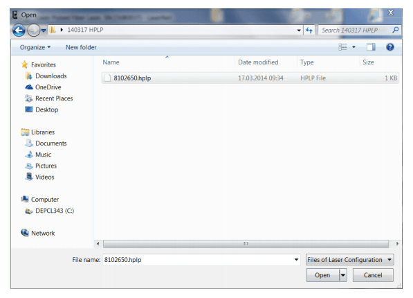
Figure 9-11: Selecting the HPLP file
- Wait until the new configuration is updated.

Figure 9-12: Update progress
- Then restart the laser.
The laser firmware is now up to date.
9.4.6 Resetting critical errors
If the laser reports the alarm Critical error, you cannot reset theerror by pressing the Reset button.
If you would like to continueworking with the laser anyway, you can reset a critical error only by entering a code.
To do this, proceed as follows:
- Start the LaserNet software.
- Make certain that there is a network connection to the laser.
3. Check whether the guide laser (guide laser channel 0, if a beam
switch is installed) is visible at the fiber in the combiner
module and at the exit of the process optics.
4. In LaserNet under ConfigurationLaser, select the submenu
Reset Critical Errors.
The dialog window Reset Critical Errors appears.
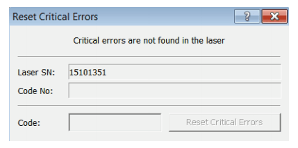
Figure 9-13: Resetting critical errors
5. Contact the competent IPG service department and give them
the laser serial number (Laser SN) and the code number
(Figure 9-13) as well as the information of whether the guide
laser is visible.
6. Send the log files (see section 9.4.2) and the events file (see
section 9.4.3) to the competent IPG service department.
An IPG service employee will provide you with the code for resetting the
critical error. The code can only be entered once for resetting the
reported critical error and only on the laser with the specified serial
number.
7. Enter this code into the input field Code (see Figure 9-13) and
click on the button Reset Critical Errors.
The critical error is reset.
10 Decommissioning and disposal

10.1 Temporary shutdown
1. Turn the key switch on the front door of the Laser and the main
switch to OFF.
2. Disconnect the power from the mains power supply and secure
it against mistaken reactivation.
3. Close the supply lines for water.
4. Remove the connections for water.
5. Drain all coolant from the product.
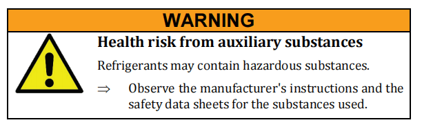
- Blowout the water cycles with oil-free compressed air.
- Clean upleaked coolant immediately.
- Closethe connections for water with the closing plugs.
10.2 Final shutdown
1. Turn the key switch on the front door of the Laser and the main
switch to OFF.
2. Disconnect the power plug from the supply voltage and secure
it against accidental reconnection.
3. Remove the connections to the external interface.
4. Close the supply for house water.
5. Remove the feed lines for water from the product.
6. Drain all coolant from the product.
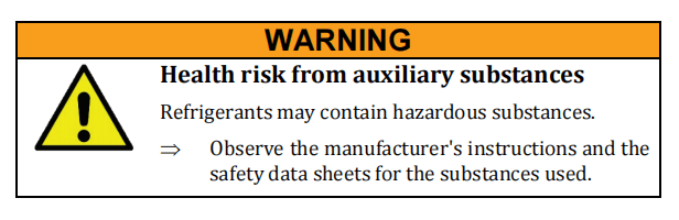
7. Blow out the water cycles with oil-free compressed air.
8. Clean up leaked coolant immediately.
9. Close the connections for water with the closing plugs.
10. Remove all connections on the product.
11. Remove the fiber from the process optics and protect the fiber
with the provided protective cap. Follow the instructions in
section 5.5.4.
12. Pack up all lines and hoses.
Storage
13. Bring the product and all accessories to the intended storage
location until used again or until removal. Follow the
instructions in section 4.2.3. The storage location must be dry
and clean.
14. Observe the storage conditions (see supplied technical data).
10.3 Disposal

The following points are to be observed when disposing of the
product, the accessories and the operating and auxiliary materials:
. Observe national provisions on site
. Observe company-specific guidelines
Following proper disassembly, the disassembled individual parts are
to be recycled:
. Scrap remaining metallic material
. Recycle plastic elements
. Dispose of other components sorted by material property
Electronic waste, electronic components, lubricants and auxiliary
substances are subject to special waste treatment and may only be
disposed of by approved specialized personnel.
National disposal regulations must be observed with respect to the
environmental disposal of the machine.
11 LaserNet software
The software LaserNet is included with the laser. You can operateand monitor the laser with the help of LaserNet. Fast Ethernet 100Mbit/s is used as the interface between the computer and the laser.
11.1 System requirements
In order that you can operate the LaserNet software on your PC, thefollowing system requirements must be met:
. Pentium III/IV 1 GHz or compatible (recommended – Pentium IV 2 GHz)
. RAM 256 MB (recommended 512 MB)
. Screen resolution 1024х768 (XGA) 256 colors (recommended – True Color)
. Ethernet 100 Mbit
. CD/DVD drive (only for installation)
. Operating system Windows XP / VISTA / 7
11.2 Installing the software
The installation wizard installs the software on your computer and places a shortcut on your desktop for starting the software, ifdesired.
- Insert the installation CDinto the CD drive of your computer.
- Open the folderLaserNetSetup.
- Clickon the installation file LaserNet Setup.exe
The installation wizard appears.
- Clickon Next.
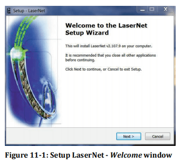
| 5. | Select the installation directory for the software. | ||
| 6. | Confirm with Next. | ||
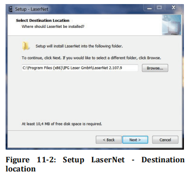
| 7. | Select a name for the Start menu folder | |
| 8. | Confirm your selection with Next. |
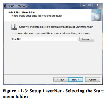
- Click on Next.

| 10. | Click on Install to start the installation. |
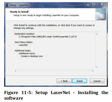
| 11. | Click on Finish to finish the installation. |
| 12. | Keep the option Launch LaserNet selected, to start LaserNet after the Installation is finished. |
LaserNet is nowinstalled on your PC.
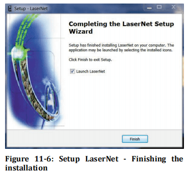
11.3 Establishing a connection to the laser
In order that you can establish a connection between your computer
and the laser, you must connect the computer and the laser to the
same local network. Proceed as follows:
1. Connect a network cable to the Ethernet interface of the laser
and to the network card of your computer.
2. In the Windows operating system, open the dialog window
Internet Protocol Properties (TCP/IPv4) and enter there the
standard IP address of the computer (Table 11-1 and Figure
11-7).
3. Change the last 3 digits of the IP address. The IP address of the
laser and the computer must differ in the last three digits.
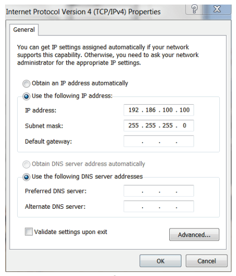
Figure 11-7: Internet Protocol Properties
- After entering the IP address, click on OK.
5. Click on the file LaserNet.exe or the shortcut
LaserNet[VERSION] to start the software.
The following screen appears (Figure 11-8).
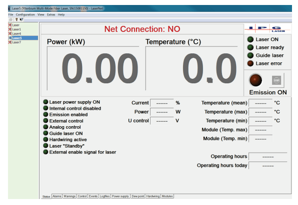
Figure 11-8: LaserNet – No connection
- Clickin the menu bar on the menu Configuration.
A drop down menu appears.
- Inthe drop down menu, select the submenu IP Configuration.
A dialog window appears.

Figure 11-9: IP Configuration dialog window
8. In the IP Configuration dialog window, click on the button Add
to create a laser name.
The first line of the dialog window is filled in.

9. Activate the cell Disabled in the State column by double-clicking
on it.
A drop down menu appears.
10. Click in the drop down menu on Enabled to activate the laser.
11. Click on OK.
Once the connection between the laser and the program has been
established, the connection status in the LaserNet user interface
changes from Net Connection: NO to Net Connection: OK (Figure
11-10).
The connection may take several seconds.
11.4 Starting LaserNet
1. Before starting LaserNet, make certain that the laser and
computer are connected to the same local network (LAN) and
are configured appropriately (see section 11.3).
2. Click on the file LaserNet.exe or the shortcut
LaserNet[VERSION] to start the software.
3. The connection may take several seconds.
The following screen appears (Figure 11-10).

Figure 11-10: LaserNet tab Status
11.5 LaserNet user interface
Figure 11-11 shows the user interface of the LaserNet software. Table 11-2 contains a brief description of the main information elements of the software.

Figure 11-11: LaserNet user interface
| Item | Designation | Description | |
| 1 | Menu bar | Via the menu bar, you have access to the menus, submenus and options of the software. Various settings can be configured in LaserNet using the 5 main menus. | |
| 2 | Laser selection | You can manage multiple lasers via the LaserNet software. All lasers that have been connected to the software are shown in this field. If the network connection to a laser is deactivated,this is indicated by an X over the laser icon. If a network connection to a laser is active, the red X over the corresponding laser icon disappears. | |
| 3 | Power and temperature display | Shows the current output power and module temperature of the selected laser. | |
| 4 | Tab | Status, warning and fault messages (see also Annex A) as well as actual values and operating parameters are displayed in the tabs. In the event of a warning message, the current value fields have an orange background; in the event of an alarm, this background is red. In addition, you can configure settings relating to laser operation in some tabs (e.g. Control). The number and type of the tabs varies depending on the configuration of the laser. | |
| 5 | Connection status | Displays the status of the network connection to the selected laser. | |
| 6 | Status indicator | Laser ON | Main power supply is ON / OFF |
| Laser ready | Laser is ready / not ready to enable the laser radiation | ||
| Chiller ready | Chiller is ready / not ready. Chiller ready is a prerequisite for laser ready. | ||
| Guide laser ON | If no chiller is configured, the status of the guide laser is displayed instead of the chiller. | ||
| Laser error | Laser has / does not have an error | ||
Table 11-2: Description of the LaserNet user interface
11.6 LaserNet menu structure
Table 11-3 offers an overview of the LaserNet menu structure. Adetailed description of the individual menus can be found in the following sections of this operating manual.
| File menu |
| Monitor File….input window |
| Exit |
| Configuration menu |
| IP Configuration… input window |
| Laser Change Access Right Reset Critical Errors Fieldbus Settings Advanced Settings Configuration Update Configuration Overview |
| Enable Control |
| Change Password |
| LaserNet SettingsControl Options Events Paths |
| LanguageLanguage selection (German, English, etc.) |
| View menu |
| Toolbar |
| Status Bar |
| Extras menu |
| Program Editor |
| QCW Pulse Editor |
| QCW Program Editor |
| Access Rights |
| Fieldbus Debug Window |
| Help menu |
| LaserNet Help |
| Setup TeamviewerQS |
| About LaserNet |
Table 11-3: LaserNet menu structure
11.6.1 File
Monitor File
In the submenu Monitor File, you have the option of recording
specific signals. This recording can be used later for fault analysis.
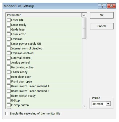
Figure 11-12: Monitor file settings
To record the signals, do as follows:
1. Place a check mark in front of each signal you would like to
record.
2. Set the scanning period using the drop down menu Period.
3. Place a check mark in front of the field Enable the recording of
the monitor file.
4. Activate the recording by clicking on OK.
The created file will be saved in the folder LaserNetLaser in the
format *.txt.
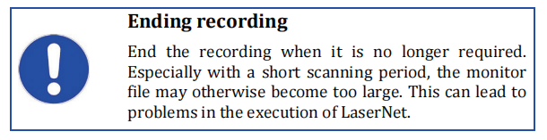
⇒ Remove the check mark from the field Enable the recording of
the monitor file to end the recording of the monitor file.
Exit
You can close the software via the submenu Exit.
11.6.2 Configuration
IP Configuration
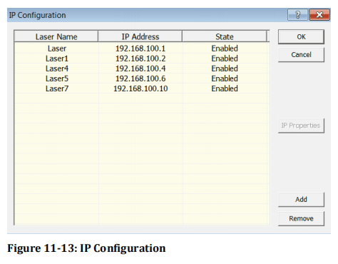
In the submenu IP Configuration, you can change the laser name and the IP address of a laser as well as activate or deactivate a laser.
The laser name is used for identification if you control and monitormultiple lasers with one computer. Ensure that you assign each lasera unique name.
In the IP address column, the IP address for the laserwith the corresponding name is assigned.
If an active connection to a laser exists, the button IP Propertiesbecomes available (only in Supervisor Mode).
Clicking on this button opens an input window in which you can change the IP address of the laser.

Figure 11-14: IP Options
Laser Change
Access Right
In the submenu Change Access Right, you can change between four
different password-protected access levels. The following access
levels are available:
. Monitoring
. Operator
. Engineer
. Supervisor
The currently selected access level is marked with a check mark. The
various user rights can be viewed via the menu path ExtrasAccess
Rights.
When changing from one access level to another, a password must be
entered. By default, no password is set. However, the Supervisor can
set and change passwords for all access levels via the menu path
ExtrasAccess Rights.

Laser Reset
Critical Errors
If the laser reports the alarm Critical error, you cannot reset the
error by pressing the Reset button. You can only reset a critical error
by entering a code.
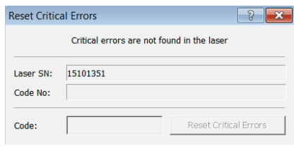
Figure 11-15: Resetting critical errors
The code can be obtained by contacting the competent IPG service department (see section 9.4.6).
Laser Fieldbus
Settings
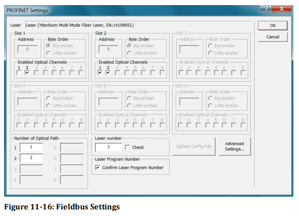
Before you can work with your fieldbus interface, you must configuresome parameters via the LaserNet software during initialcommissioning.
If you are working with a multiport interface, you must set the corresponding parameters for every fieldbus card during the initial commissioning.
The parameters are described briefly below.
Address
In this field, you can define the slave address for each fieldbus card. If a master accesses multiple slave cards, the slave cards must have different addresses.
If multiple independent masters access differentslave cards, the slave cards can have the same MAC ID.
Byte order
In this field, you can define the byte order for the communication(little endian – big endian). You can set the byte order for communication separately for each slot.
Enabled optical channels
In this field, you can enable the optical channels for the respectiveslot (slave card).
Only select optical channels can be requested andused by the respective slot. You can assign multiple slots, i.e. slavecards, to a channel.
This option depends on the configuration.
Optical path number
These fields display the current coding for each optical channel of thebeam switch.
The coding corresponds to the optical path that mustbe requested by the system owner’s PLC unit.
If the first optical channel of the beam switch was coded with the value 10, the PLCunit must set optical path number 10.
The coding is performed in the laser.
This option depends on the configuration.
Laser number
The current coding of the laser is shown here. The coding corresponds to the laser number that must be requested by the system owner’s PLC unit.
If the laser is coded with value 6, the PLCunit was set laser number 6. The coding is performed in the laser itself.
Check
If this option is activated, the laser control checks whether the rightlaser number is sent by the system owner’s PLC unit.
If the lasernumber is not correct, the laser reports a fault.
Laser program number
If you activate the option Laser program number, the input signal of the external control Laser program number is immediately reported back to the external control.
Otherwise, the laser program number isonly reported after receipt of the signal Program Start along with theexecution of the program.
Update configuration file
Clicking this button opens a file browsing window with which youcan upload an update file (dbm format) for configuration of your Profinet slaves.
This update file can be obtained from IPG LaserGmbH upon request.
Advanced settings
Clicking this button opens an input window in which you can changevarious parameters depending on the available fieldbus interface.
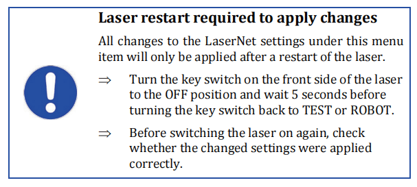
Laser
Advanced
Settings
Automatic Switching OFF
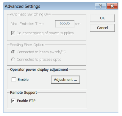
Figure 11-17: Advanced settings
In the submenu Advanced Settings, you can configure the emission time of the laser.
To do this, enter the desired emission time in the input field Max. Emission Time (see Figure 11-7).
The emission will stop after the configured time has elapsed, starting from the time atwhich the status Emission enabled was activated.
If you activate thefield “De-energizing of power supplies”, the main power supply will also switch off as soon as the emission stops.
The automatic switching off function is deactivated if you enter zero (0) secondsinto the input field Max. Emission Time.
Feeding Fiber Option
With this function, it is possible to select whether to work with the installed integrated optics (if present) or directly with the feeding fiber.
This option depends on the configuration.
Operator power display adjustment
You have the option of displaying the actual power measured at theoutput of the process optics within the LaserNet user interface in the power display area (see Figure 11-11). To change the power display, proceed as follows:
- Clickon the box Enable.
- Clickon the Adjustment button.
An input window appears.
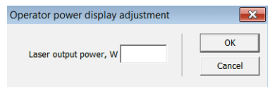
Figure 11-18: Operator power display adjustment
- Enterthe measured power value in watts. 4. Click on OK.
The value entered by you will appear in the power display field.
Anasterisk will appear above the power display field (see Figure 11-19) to indicate that this option is active.

Figure 11-19: Operator-specific power display
Remote Support
This option allows the competent IPG service department to access
the laser (events, warnings, errors, etc.).
Laser
Configuration
Update
Via the submenu Configuration Update, you can perform an update of
the laser configuration as well as the firmware. Clicking on the
submenu opens a file browsing window. In this browsing window,
you can select the update file (*.hplp) to be loaded. The update file
can be obtained from IPG Laser GmbH upon request.
Laser
Overview
Configuration
In the submenu Configuration Overview, you will find information
about the laser (e.g. serial number, ID, firmware) as well as about the
laser configuration (e.g. parameters, options).
Enable Control
Activate this option to apply password protection to all operating
functions in LaserNet in order to prevent unauthorized access.
Change Password…
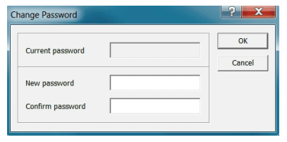
Figure 11-20: Change Password
In this dialog window, you can set a computer-specific password forLaserNet, independent of access rights.
Activating the password will lock out the LaserNet operating elements on the Control tab.
This lock can be removed by entering the password via ConfigurationEnable Control.
If you lose this password, it is possible to delete it. To do this,proceed as follows:
1.Open the “Registry Editor”. The value “user” is stored under the
following path.
HKEY_Current_UserSoftwareIPG Laser GmbH LaserNet Settings
2. Delete the user value.
3. Restart LaserNet.
You can now create a new password or work with LaserNet without
password protection.
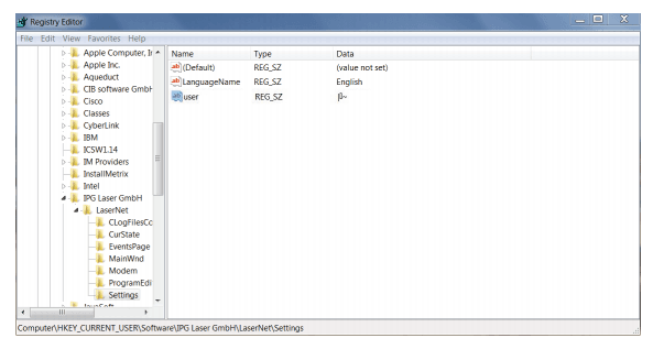
Figure 11-21: Registry Editor
LaserNet
Settings
Control
Options
In this dialog window, you can enable or disable control options in
LaserNet.
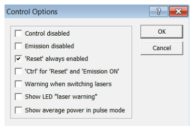
Figure 11-22: Control Options
⇒ Place a check mark in the corresponding field to enable an
option.
The following table contains a short description of the control
options.
| Control option | Description |
| Control disabled | All operating functions in the LaserNet Control tab are deactivated |
| Emission disabled | Emission ON / Emission OFF button is disabled |
| ‘Reset’ always enabled | The Reset button remains enabled even in the ROBOT mode |
| Ctrl for Reset and Emission ON | Control must be pressed simultaneously with the button Reset or Emission ON in order to issue the command |
| Warning when switching lasers | A warning is displayed when switching between different lasers. |
| Show LED “laser warning” | Replaces the LED indicator Chiller ready in the status display (section 11.8.1) with Laser warning |
| Show average power in pulse mode (only for QCW lasers) | In the power display (section 11.5), this shows the average output power instead of the peak power when the laser is operated in pulsed mode. |
Table 11-4: Control Options
LaserNet
Settings
Events…
In the dialog Figure 11-23, you can define the maximum number of
events that should be saved in the file events4dat. This allows you to
limit the file size.
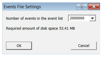
Figure 11-23: Defining the number of events for the events list (events4.dat)
LaserNet
Settings
Paths

Figure 11-24: Configuring the save locations for LaserNet files
In this submenu, you can configure the save locations for the
following files:
. Configuration file
. Log files
. Help and language files
The default settings are shown in the following table.
Language
In the submenu Language, you can select the desired language for
LaserNet. If language options are displayed as □□□, the
corresponding library file is not installed under Windows.
11.6.3 View
Status Bar Enable/disable this option to show/hide the status bar.
Toolbar Enable/disable this option to show/hide the toolbar.
11.6.4 Extras
Program
Editor
In the submenu Program Editor, you can create and edit laser
programs. A detailed description of the LaserNet program editor can
be found in section 11.9.
QCW Pulse
Editor
Via the submenu QCW Pulse Editor, you can create laser programs.
This option depends on the configuration.
QCW Program
Editor
Via the submenu QCW Program Editor, you can edit already created
laser programs.
This option depends on the configuration.
Access Rights
In the submenu Access Rights, you can set rights for the various
LaserNet access levels. In addition, you can set or change the
passwords for the access levels. No passwords are assigned by
default.

Figure 11-25: Overview of access rights
⇒ Click on the button Passwords to open the input window for changing the passwords.
A dialog window appears.
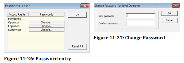
⇒ Click on the button Change for the access level to change the password.
⇒ Enter the new password and confirm with OK.
Fieldbus Debug Window
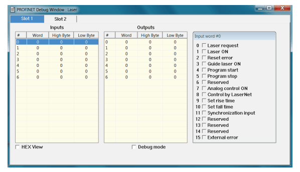
Figure 11-28: Fieldbus Debug Window (example)
In the submenu Fieldbus Debug Window, the communication between master and slave is displayed.
If the debug mode is activated in this submenu, all fieldbus output bits can be set manually.
In this case, the laser will not respond to input bits.
If debug mode is not activated, no outputs can be set manually.
11.6.5 Help
LaserNet Help
The submenu LaserNet Help opens the LaserNet offline help (if
installed).
Setup
TeamviewerQS
Via the submenu Setup TeamviewerQS, you have the option of
allowing service technicians of IPG Laser GmbH to access your
computer.
About
LaserNet
The submenu About LaserNet shows the version number of the
currently installed LaserNet software.
11.7 LaserNet status indicators
LaserNet uses three different LED indicators. The LED indicators arelisted and explained in the following table.
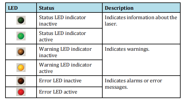
Table 11-6: LaserNet status indicator description
11.8 LaserNet tabs
The tabs listed in this section are examples based on which theLaserNet software is described.
The type and number of the tabs as well as the status, warning and fault messages shown vary based on the configuration of the laser.
11.8.1 Status tab
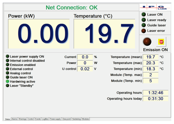
Figure 11-29: Status tab
This tab displays status messages and actual values of the laser.
The green status LED indicator, which is shown in front of every status message, indicates whether a status message is active or inactive (see section 11.7).
A detailed description of the status messages can be found in Annex A, Status tab. The actual values are described briefly below.
| Actual values | Description |
| Current | Pump current in percent |
| Power | Laser output power in watts |
| Water flow (optional) | Water flow in liters per minute |
| Int. control voltage | Analog control voltage for setting the module power |
| Temperature (mean) | Average temperature determined from the values of the modules with the maximum and minimum temperature |
| Temperature (max) | Temperature of the module with the highest temperature |
| Temperature (min) | Temperature of the module with the lowest temperature |
| Module (Temp. max) | Number of the module with the highest temperature |
| Module (Temp. min) | Number of the module with the lowest temperature |
| Operating hours | Total operating hours of the laser |
| Operating hours today | Operating hours of the laser on the current day |
Table 11-7: Status tab actual values
11.8.2 Alarms tab

Figure 11-30: Alarms tab
Alarm messages of the laser are displayed on this tab (Figure 11-30).
A detailed description of the individual alarm messages as well asinstructions for eliminating the faults can be found in Annex A,Alarms tab.
11.8.3 Warnings tab
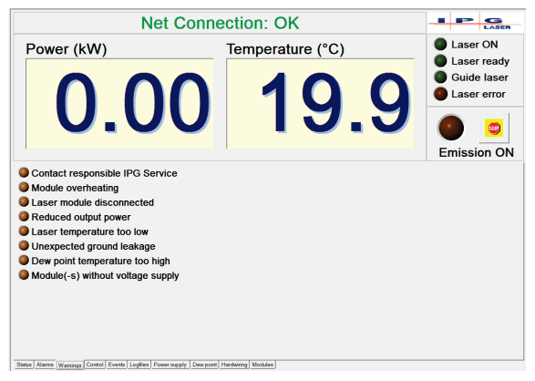
Figure 11-31: Warnings tab
Warning messages of the laser are displayed on this tab (Figure11-31).
In contrast to alarms, warning messages do not interrupt the laser operation. A more detailed description of the individual
warning messages as well as instructions for eliminating the warnings can be found in Annex A, Warnings tab.
11.8.4 Control tab
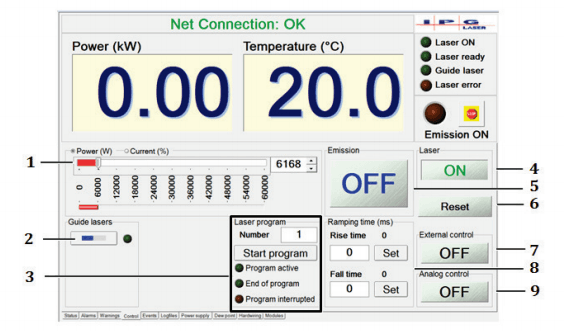
Figure 11-32: Control tab
The buttons on this tab (Figure 11-32) reflect the current status of the laser or allow you to configure various settings relating to laser operation.
If the laser is in ROBOT mode all buttons (except for Reset) are grayed, i.e. disabled, by default.
| Item | Description |
| 1 | In this tab section, you can set the laser power with a slider or enter a value directly into the input field to the right of the slider. A numeric entry must be confirmed with ENTER. You can specify the power absolutely in watts or as a percentage of the pump current. The laser should not be operated with a pump current of less than 10% according to the technical data. If the laser is equipped with the option “Linearization”, you can specify the power either absolutely in watts or as a percentage of the total power. |
| 2 | In the guide lasers section, you can switch on the guide laser. If the guide laser is active, the LED indicator for the guide laser lights up green. |
| 3 | In the laser program tab section, you can select a laser program (number 1-50), start/stop the current program and monitor its status. In the input field Number , enter the desired laser program. Click on the button Start program to start the laser program. Upon starting the laser program, the name and the function of the button Start program changes to Stop program . At the same time, the status indicator Program active is activated and remains active until the program ends. If the program ends without an error, the status indicator End of program is activated. The status indicator remains active until you start a new program or click on the button Reset. The name and the function of the button Stop program change again to Program Start when the program ends. Clicking on the button Stop program while the program is running stops the program and activates the status indicator Program interrupted. With the button Reset, you can deactivate the status indicator Program interrupted. |
| 4 | By clicking on this button, you can switch the main power supply on and off (ON/OFF). |
| 5 | By clicking on this button, you can switch the laser emission on and off (ON/OFF). |
| 6 | With the button Reset, you can reset all alarms, except for the message Critical error once the reason for the alarm has been removed. |
| 7 | By clicking on this button, you can switch the external control on and off. The status is indicated on the button itself. |
| 8 | In the tab section Ramping time, you can set the ramping rise and fall times. Enter the desired value (max. 5000 ms) into the corresponding input field and confirm your entry with Enter or by clicking on the button Set . |
| 9 | By clicking on this button, you can switch the analog control on and off. The current status is indicated on the button itself. |
Table 11-8: Control tab description
11.8.5 Events tab
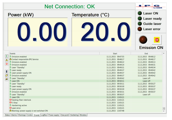
Figure 11-33: Events tab
Events of the laser are displayed on this tab (Figure 11-33).
The symbols on the left serve as filters.
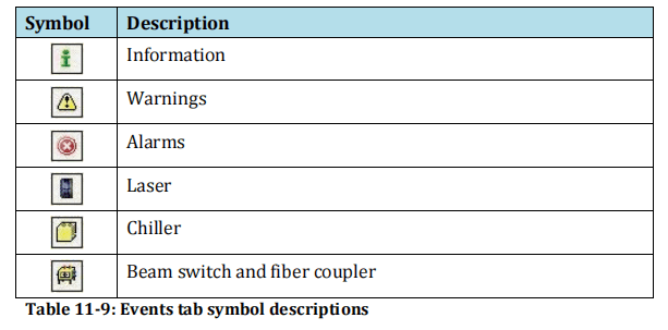
Via the context menu (right-click in the Events column), you can also:
. Sort the events by time
. Save the events as a .txt file
. Delete the events
You limit the number of saved events under the path ConfigurationLaserNet SettingsEvents. Once you close LaserNet, theevents are saved in the file
events4.dat in the directory IPG LaserLasername.
11.8.6 Logfiles tab

In this tab (Figure 11-34), you can select and download the created log files. The log files are saved in the laser memory. In event of a fault, you can download the corresponding
files to your computer and send them to the competent IPG service department.
To do download the files, proceed as described in section 9.4.2.
11.8.7 Power supply tab
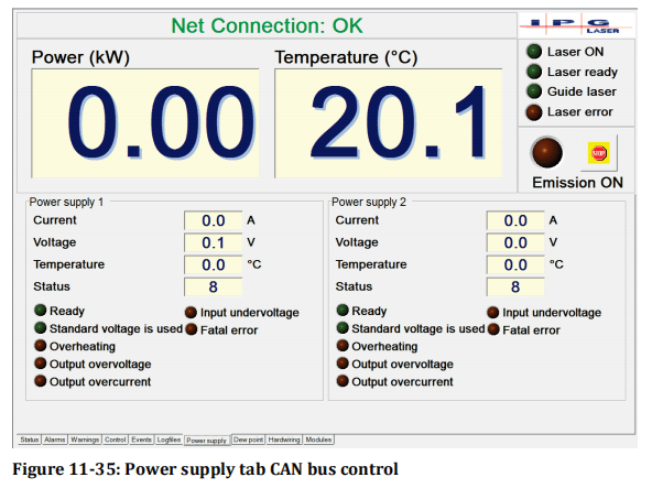
On this tab (Figure 11-35), the actual values as well as status messages and alarms of the installed main power supplies are displayed.
A detailed description of the individual status and alarm messages as well as instructions for eliminating the faults can befound in Annex A, Power supply tab.
The displayed actual values are described in the table below.
| Actual values | Description |
| Current | Output current of the power supply |
| Voltage | Output voltage of the power supply |
| Temperature | Temperature of the power supply |
| Status | Status of the power supply (internal code IPG) |
Table 11-10: Power supply tab description
11.8.8 Chiller tab
Actual values of the laser chiller are displayed on this tab (Figure11-36).
| IPG chiller | The status, warning and fault messages of the chiller can be accessed via the side tabs (see Figure 11-37 and Figure 11-38). In contrast to alarms, warning messages do not interrupt the chiller operation. A detailed description of the individual alarm and warning messages as well as instructions for eliminating the faults can be found in Annex A, Chiller tab. |
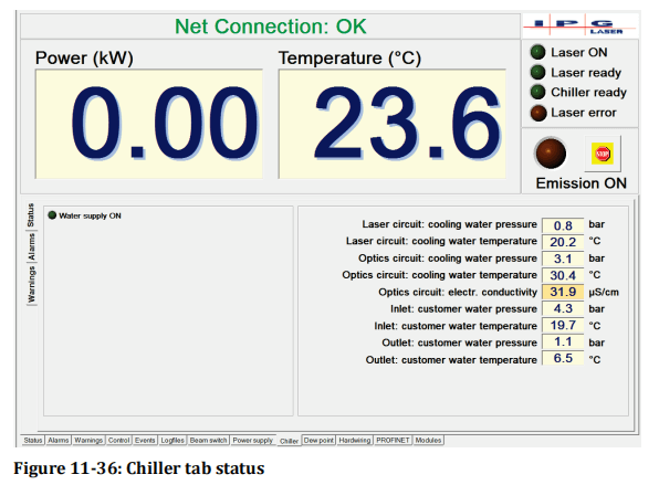
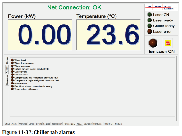
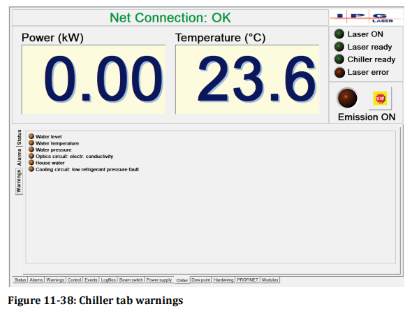
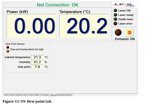
Warning and alarm messages as well as actual values concerning the
dew point are displayed on this tab (Figure 11-39). A detailed
description of the warning and alarm message as well as instructions
for eliminating the fault can be found in Annex A, Dew point tab.
The displayed actual values are described in the table below.
| Actual values | Description |
| Cabinet temperature | Measured temperature in the laser cabinet |
| Humidity | Measured humidity in the laser cabinet |
| Dew point | Calculated dew point in the laser cabinet |
| Status | Status of the power supply (internal code IPG) |
Table 11-11: Dew point tab description
11.8.10Hardwiring tab
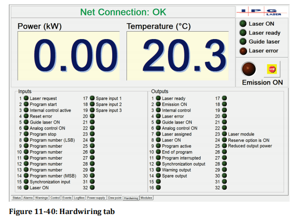
Input and output signals of the hardwiring interface are displayed onthis tab (Figure 11-40). For a more detailed description of the signals of the hardwiring interface, refer to the supplied technical data.
11.8.11 Modules tab

This tab (Figure 11-41) contains status information about the
installed laser modules. You can activate or deactivate individual
modules. The central elements of this tab are described in the table
below.

11.9 LaserNet program editor (LP editor)
With the program editor of the LaserNet software, you can create upto 50 custom laser programs. The program editor can be opened via the path Menu ExtrasProgram Editor.
11.9.1 LaserNet program editor editing window
Figure 11-42 shows the editing window of the program editor. Withthis window, you can open and edit or create a new laser program(LP).
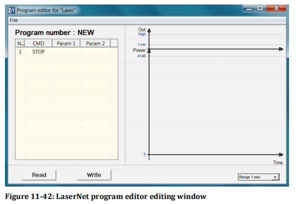
Commands are entered in the input field on the left side of the user
interface; on the right side, the program is displayed in the form of a
diagram (laser output power / time).
Column 1 (No) of the input field shows the command number,
column 2 (Command) the command itself. Upon opening the
program editor, the command STOP is listed in line 1 by default. In
the columns 3 (Param1) and 4 (Param2), you can enter the
parameters for each command. You can enter the commands and
parameters either via the key board or via a drop down menu. The
drop down menus for the columns 2, 3 and 4 appear as soon as you
click on the field.
A new line can be inserted either by left-clicking on any open line or
right-clicking on an existing line (the option “Insert line” appears).
The default command “STOP” automatically appears in the new line, but
this can be changed to any command.
To delete an existing command line, right-click on the corresponding
line and select the option Delete line. If the laser program consists of
only a single line, this cannot be deleted.
To save a laser program in the laser, click on the button Write.
A dialog window appears. In this dialog, you can assign the laser
program a number between 1 and 50 and save the program under
this number. Assigned program numbers have a red background,
available program numbers are green.

To load a previously saved laser program, click on the button Read(Figure 11-42) and select the desired program number (1-50).
After loading the laser program, the current program number in thetitle of the table is shown in the editing window.
You can also save a laser program as a file on the computer. To dothis, click in the program editor on the menu File and then on Save(Figure 11-42).
Enter the path of the save location and the file name, then click on Save.
The program file is stored as a text file with the extension “.Inp” and can be viewed and modified in any standard text editor.
To load a laser program that you have saved on your computer as atext file, click in the program editor on the menu File and then on Open.
Select the desired file.
11.9.2 Command list for laser programs

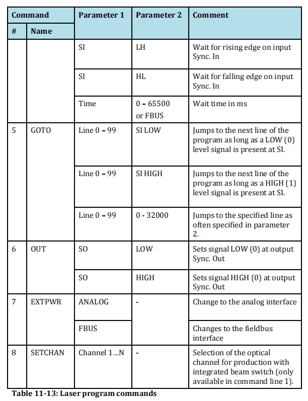
11.9.3 LaserNet program editor command descriptions
| STOP | Switches off the emission, switches the analog control off, stops the execution of the laser program and sets the status End of program to HIGH. The STOP command must be set as the last command of a laser program. |
SPT Define the emission power over a period of time
Linear ramp function: Switches the laser emission on and defines thepower to be reached within a specific time.
Parameter 2 defines the power [W], parameter 1 defines the time[ms], in which the power will be reached.
The parameters can be assigned in the following ways:. Manual input as numerical value in the program editor. Via the fieldbus interface (FBUS)
If a previous command switched on the laser emission and set the laser power, the laser power of this command is used as the initialpower for the command SPT; otherwise the initial power is 0 W.
The command SPT stops the execution of the command EXTPWR ifthis was previously switched off.
SPR Define the emission power over a ramping time
Linear ramp function: Switches the laser emission on and defines thepower to be reached over a defined ramping time.
Parameter 2 defines the power [W], parameter 1 defines the powerincrease (ramping time) [W/ms] with which the specified power willbe reached.
The command has a function similar to the SPT command (seedescription above).
WAIT Wait for event
Parameter 1 defines the event type:
. Synchronization signal Sync. In
. Time [ms] Time.
Parameter 2 determines the event:
. Falling edge
. Rising edge
. State LOW
. State HIGH
. Expiration of the wait time [ms] Time
The parameters can be assigned in the following ways:
. Manual entry in the program editor
. Via the fieldbus interface (FBUS) for the event type Time
GOTO Goto command
Jumps to the defined command line and executes all subsequentcommands up to GOTO in a loop.
Parameter 1 indicates the number of the command line (0 – 99) as ofwhich the command set should be executed again.
Parameter 2 determines the event:
. SI HIGH: The command set defined in parameter 1 will be executed as long as the signal HIGH is present at the synchronization input.
. SI LOW: The command set defined in parameter 1 will be executed as long as the signal LOW is present at the synchronization input.
. Counter (0 – 32767): Number of repetitions of the command set to be executed. With a value of 0, the defined command set is executed in an endless loop.
OUT Set signal “Synchronization Output”
Sets signal LOW or HIGH at the output Sync. Out
Parameter 1 selects a synchronization signal,
Parameter 2 sets the level (HIGH / LOW).
EXTPWR Switch to external mode
Specifies the external interface from which the value for emissionpower and the time should be read for the commands SPT, SPR and WAIT.
The execution of this command can be stopped with the commandsSTOP, SPT, SPR and EXPPWR (by selecting a different external interface).
SETCHAN Selection of the beam switch channel
For production with integrated beam switch, selects the opticalchannel. This command can only be executed in the first line of the program.
SETCHAN is only available for lasers with a beam switch.
Annex A Status, warning and fault messages
The laser welding tool software shows three types of messages:
. Status messages
. Warning messages
. Alarms
Status messages provide information about the current status of the system.
A Warning indicates the preliminary stage of an alarm. A closer look at the status or maintenance work is necessary.
An Alarm requires the elimination of the cause of the fault, adjustment work or repair / replacement of a component.
The status, warning and fault messages that can arise duringoperation of the laser are described below.
The descriptions of thewarning messages and alarms also contain instructions on troubleshooting.
To put the laser back into operation after eliminating the problem, the alarms must be reset.
For some messages, this takes place automatically; for others, you must click the Reset button in the LaserNet Control tab (section 11.8.4).
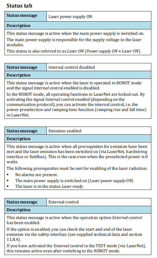

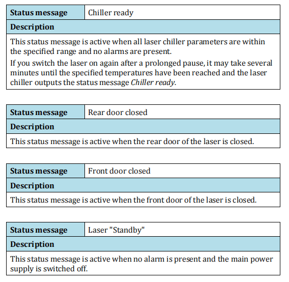

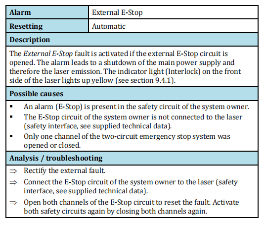
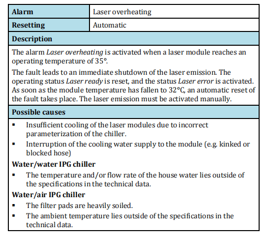
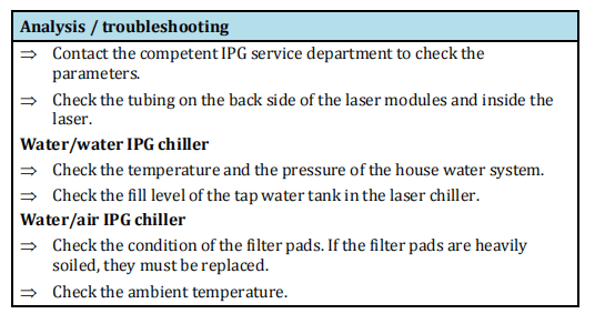
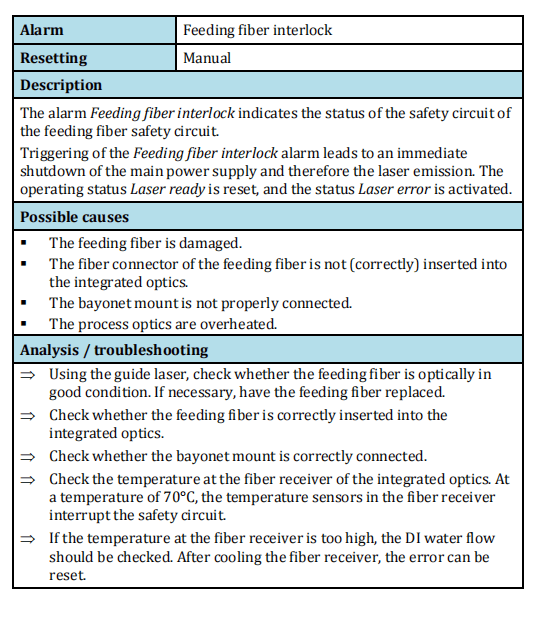
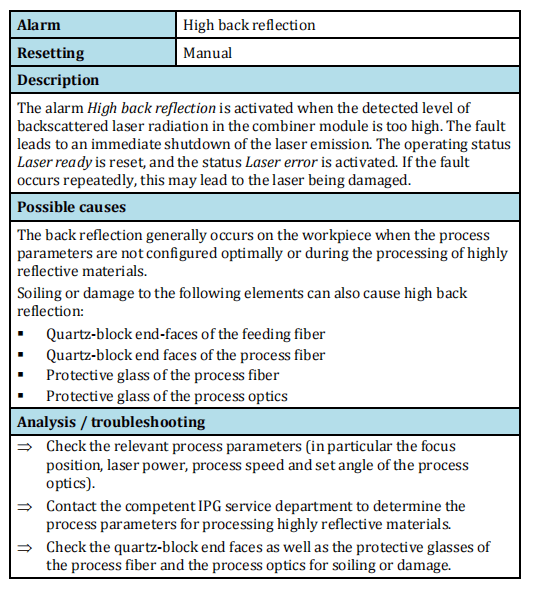
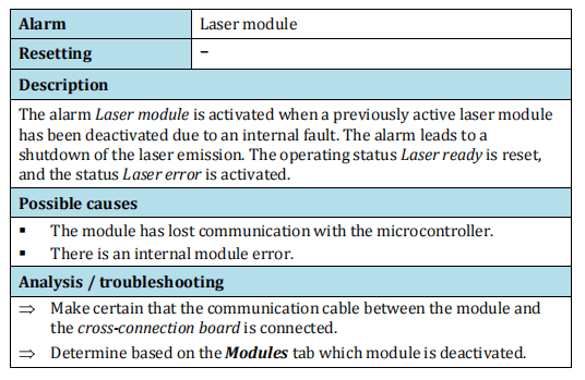
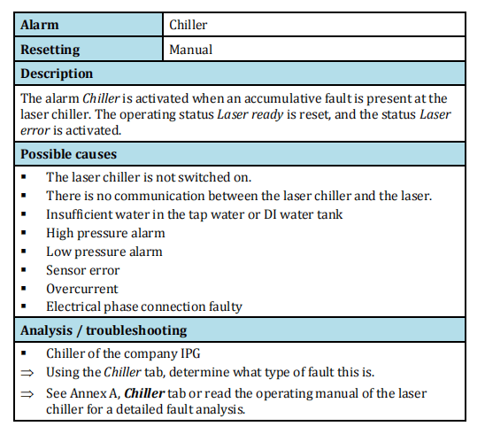
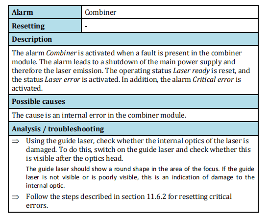


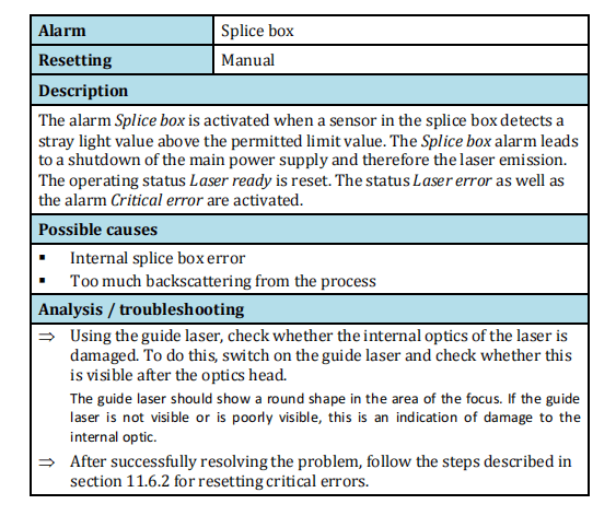
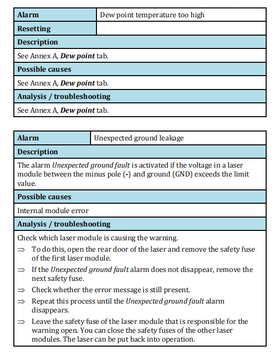
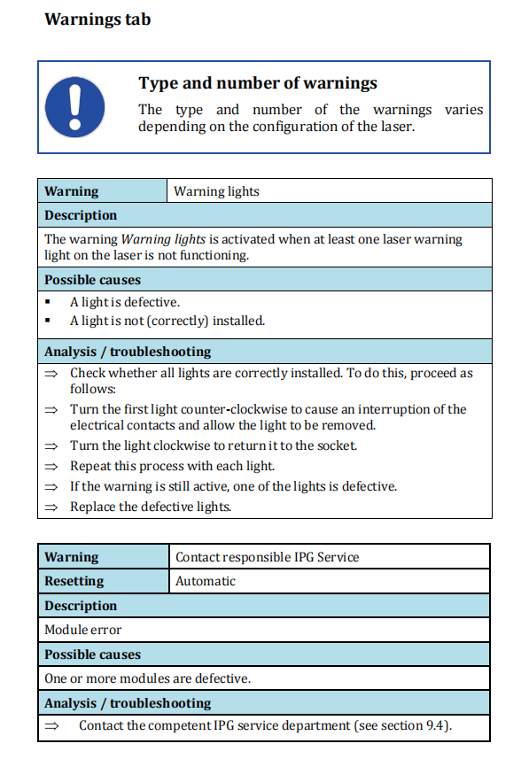

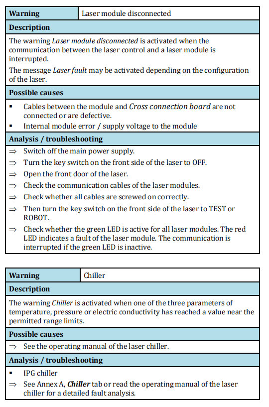

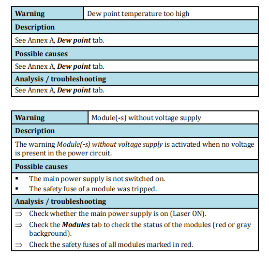

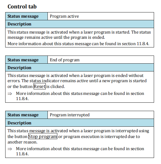

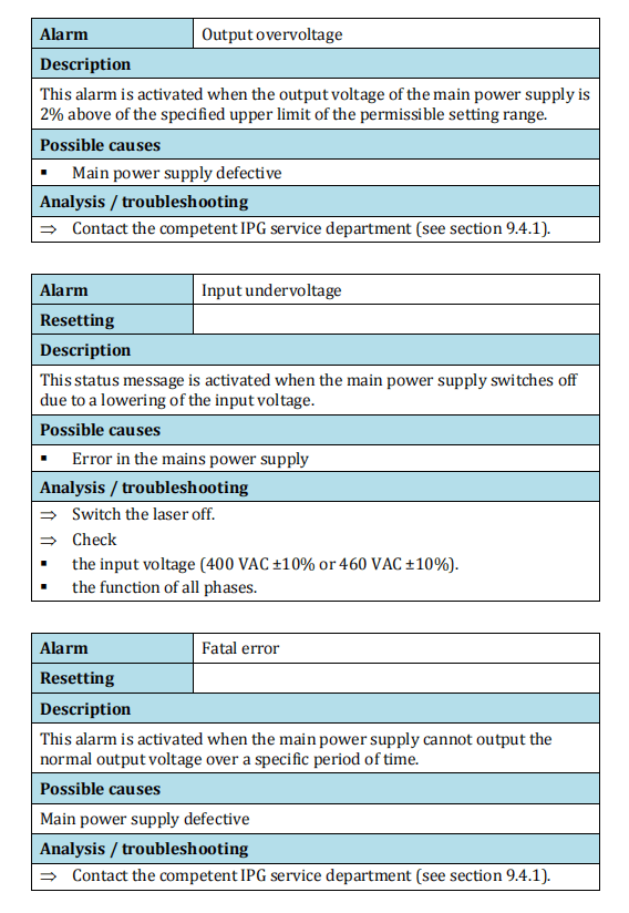
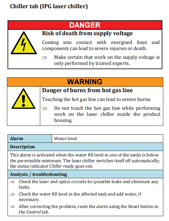
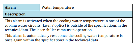

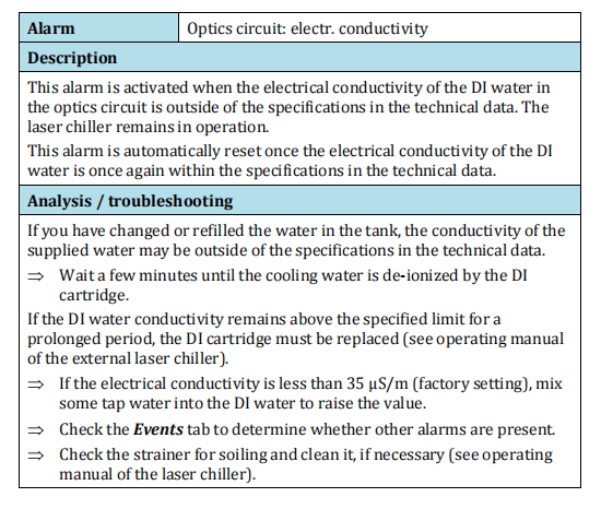


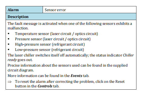
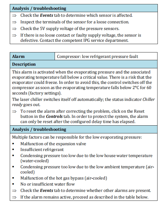
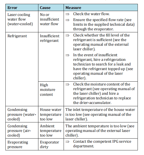
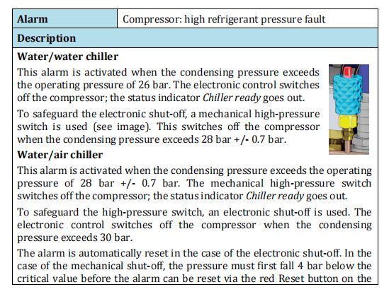
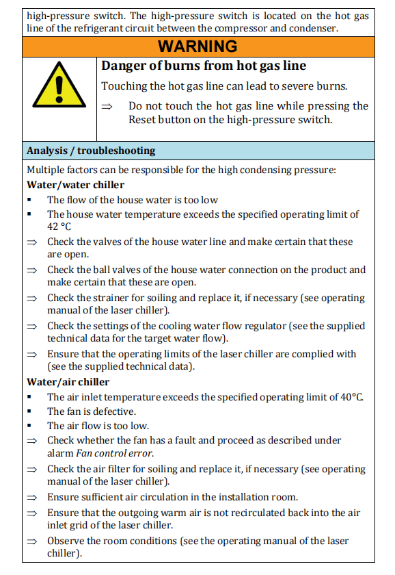

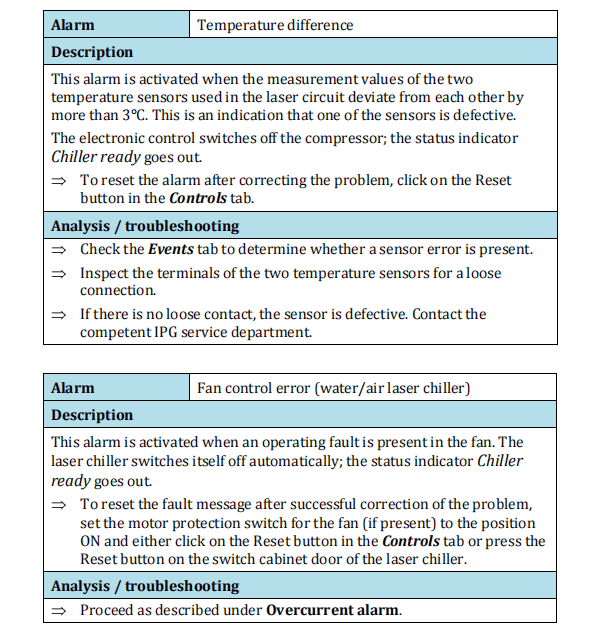
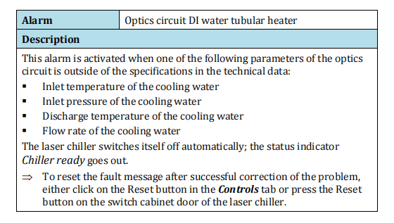
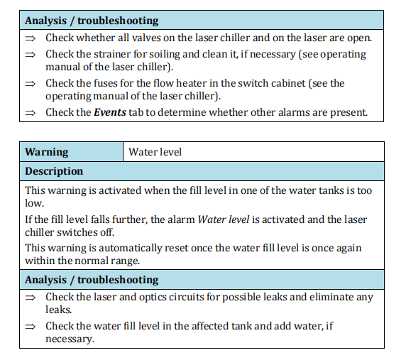

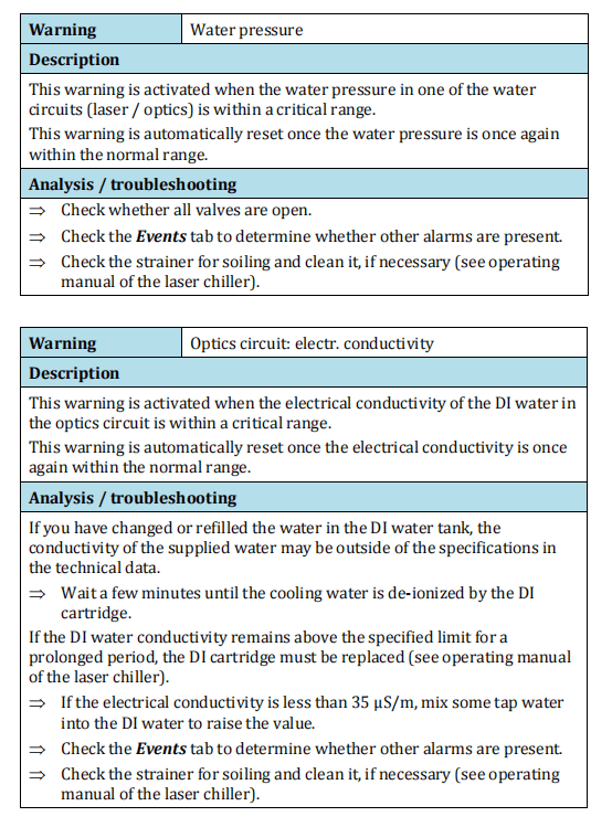

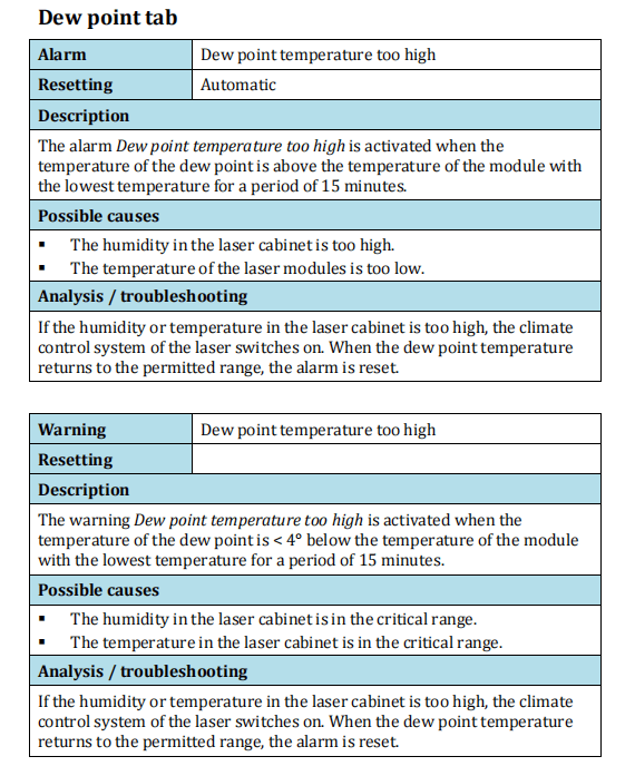

Annex B Technical data
Here you will find the information about the dew point temperaturesas well as the rating plate affixed to the product.
For additional technical information about the project, see the supplied technical data.
Dew point temperatures
Condensation:
Dew point /
cooling water
temperature
In order to prevent damage to the laser or the optics due to
condensation, the DI water temperature must be adjusted according
to the dew point table.
The problem of condensation occurs in environments in which the
temperature and humidity are too high.
To prevent condensation, the cooling water temperature must
always be kept above the dew point.
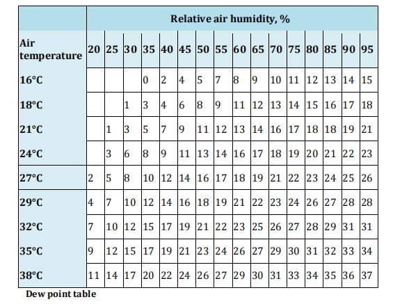
Rating plates
Laser rating
plate
The rating plate of the laser is located on the laser cabinet and
contains the following information:

Annex D Indices of figures and tables
List of figures
Figure 2-1: Safety equipment………………………………………………………………… 19
Figure 3-1: Overview of the laser …………………………………………………………. 24
Figure 3-2: Operating elements…………………………………………………………….. 25
Figure 3-3 Interfaces……………………………………………………………………………….. 26
Figure 3-4: Laser layout………………………………………………………………………….. 27
Figure 3-5 Electrical mounting plate……………………………………………………. 28
Figure 3-6: Functional principle of the fiber laser …………………………….. 29
Figure 4-1: Transport monitoring………………………………………………………… 32
Figure 4-2: Transport with pallet …………………………………………………………. 34
Figure 4-3: Hoist cable angle during crane transport……………………….. 35
Figure 4-4: Tensile load on the eye bolt………………………………………………. 35
Figure 4-5: Caster with locking mechanism ……………………………………….. 35
Figure 5-1: Water connections on the laser………………………………………… 42
Figure 5-2: Water connection on the fiber connector ………………………. 43
Figure 5-3: Supply voltage connection ………………………………………………… 44
Figure 5-4: External laser interfaces ……………………………………………………. 45
Figure 5-5: Fiber connector without (top) and with (bottom) protective cap…………………………………………………………………………………………… 46
Figure 7-1: Control tab……………………………………………………………………………. 53
Figure 7-2: Program sequence – example……………………………………………. 60
Figure 8-1 Disconnecting the fiber connector from the optics ……….. 64
Figure 8-2: Microscope with fiber connector……………………………………… 64
Figure 8-3: Fiber connector with accessories…………………………………….. 65
Figure 8-4: Cleaning the quartz-block end face………………………………….. 67
Figure 8-5: Connecting the fiber connector………………………………………… 68
Figure 8-6: Securing the fiber connector…………………………………………….. 68
Figure 9-1: Downloading log files…………………………………………………………. 74
Figure 9-2: Select date…………………………………………………………………………….. 75
Figure 9-3: Storage path for log files ……………………………………………………. 75
Figure 9-4: Select log file………………………………………………………………………… 76
Figure 9-5 Dialog window Zip All …………………………………………………………. 76
Figure 9-6 Saving events to a .txt file……………………………………………………. 77
Figure 9-7 Selecting the save location …………………………………………………. 78
Figure 9-8: Opening the configuration overview ………………………………. 79
Figure 9-9: Configuration overview……………………………………………………… 79
Figure 9-10: Updating the configuration …………………………………………….. 80
Figure 9-11: Selecting the HPLP file …………………………………………………….. 81
Figure 9-12: Update progress ……………………………………………………………….. 81
Figure 9-13: Resetting critical errors…………………………………………………… 82
Figure 11-1: Setup LaserNet – Welcome window……………………………….. 87
Figure 11-2: Setup LaserNet – Destination location ………………………….. 87
Figure 11-3: Setup LaserNet – Selecting the Start menu folder……….. 87
Figure 11-4: Setup LaserNet – Additional tasks …………………………………. 88
Figure 11-5: Setup LaserNet – Installing the software………………………. 88
Figure 11-6: Setup LaserNet – Finishing the installation………………….. 88
Figure 11-7: Internet Protocol Properties ………………………………………….. 89
Figure 11-8: LaserNet – No connection………………………………………………… 90
Figure 11-9: IP Configuration dialog window…………………………………….. 90
Figure 11-10: LaserNet tab Status………………………………………………………… 91
Figure 11-11: LaserNet user interface…………………………………………………. 92
Figure 11-12: Monitor file settings ………………………………………………………. 95
Figure 11-13: IP Configuration……………………………………………………………… 96
Figure 11-14: IP Options………………………………………………………………………… 97
Figure 11-15: Resetting critical errors ………………………………………………… 98
Figure 11-16: Fieldbus Settings…………………………………………………………….. 98
Figure 11-17: Advanced settings …………………………………………………………100
Figure 11-18: Operator power display adjustment………………………….101
Figure 11-19: Operator-specific power display………………………………..101
Figure 11-20: Change Password ………………………………………………………….102
Figure 11-21: Registry Editor……………………………………………………………….103
Figure 11-22: Control Options……………………………………………………………..103
Figure 11-23: Defining the number of events for the events list (events4.dat)……………………………………………………………………………………………104
Figure 11-24: Configuring the save locations for LaserNet files ……104
Figure 11-25: Overview of access rights…………………………………………….106
Figure 11-26: Password entry ……………………………………………………………..106
Figure 11-27: Change Password ………………………………………………………….106
Figure 11-28: Fieldbus Debug Window (example)…………………………..107
Figure 11-29: Status tab ………………………………………………………………………..108
Figure 11-30: Alarms tab ………………………………………………………………………110
Figure 11-31: Warnings tab………………………………………………………………….110
Figure 11-32: Control tab ……………………………………………………………………..111
Figure 11-33: Events tab……………………………………………………………………….113
Figure 11-34: Logfiles tab……………………………………………………………………..114
Figure 11-35: Power supply tab CAN bus control…………………………….114
Figure 11-36: Chiller tab status……………………………………………………………115
Figure 11-37: Chiller tab alarms ………………………………………………………….116
Figure 11-38: Chiller tab warnings ……………………………………………………..116
Figure 11-39: Dew point tab…………………………………………………………………117
Figure 11-40: Hardwiring tab ………………………………………………………………118
Figure 11-41: Modules tab ……………………………………………………………………118
Figure 11-42: LaserNet program editor editing window………………..120
Figure 11-43: Saving the laser program……………………………………………..121
List of tables
Table 2-1: Warning labels………………………………………………………………………. 22
Table 2-2: Explanatory labels………………………………………………………………… 23
Table 5-1: Required supply voltage……………………………………………………… 37
Table 11-1: Standard IP address…………………………………………………………… 89
Table 11-2: Description of the LaserNet user interface……………………. 93
Table 11-3: LaserNet menu structure………………………………………………….. 94
Table 11-4: Control Options………………………………………………………………….104
Table 11-5: Configuration default settings ………………………………………..105
Table 11-6: LaserNet status indicator description …………………………..108
Table 11-7: Status tab actual values ……………………………………………………109
Table 11-8: Control tab description…………………………………………………….112
Table 11-9: Events tab symbol descriptions ……………………………………..113
Table 11-10: Power supply tab description ………………………………………115
Table 11-11: Dew point tab description …………………………………………….117
Table 11-12: Modules tab description………………………………………………..119
Table 11-13: Laser program commands…………………………………………….122