
Fiber Laser Machine YLR Series
Part Number: P21-010106, YLR-Series SLED 3.0
Disclaimer Notice
© IPG Photonics Corporation 2015. All rights reserved. You may not copy, reproduce, transmit, store in a retrieval system or adapt this publication, in any form, in any media or by any means, without the prior written permission of IPG Photonics Corporation (IPG), except as allowed under applicable copyright laws. Permitted copies shall bear the same copyright and proprietary notices which were contained on the original version.
This User Guide is provided “as is” and is subject to change and revision without notice. IPG believes that the information provided is accurate and reliable; however IPG makes no warranty or representation, express or implied, regarding this document, including without limitation any implied warranties of merchantability or fitness for a particular use, purpose or application, either alone or in combination with any other device, equipment, apparatus, materials or process. Users must take full responsibility for their application of any products.
Further, IPG does not assume responsibility for use of the information contained in this document or for any infringement of patents or other rights of third parties that may result from its use. IPG shall not be liable for errors in or omissions from this document or for any incidental, consequential, indirect or special damages, including without limitation, lost profits, lost production costs or similar damages, in connection with the furnishing, performance or use of this material.
IPG grants no license, directly or indirectly, under any patent or other intellectual property rights from use of the information provided herein.
US Export Control Compliance (for US products only)
IPG is committed to complying with U.S. and foreign export, import and customs requirements. Export and re-export of lasers and other products manufactured by IPG are subject to U.S. and foreign laws and regulations, including the US Export Administration Regulations administered by the
Department of Commerce, Bureau of Industry and Security.
The applicable restrictions vary depending on the specific product involved, intended application, the product destination and the intended user. In some cases, an individual validated export license is required from the US Department of Commerce prior to resale or re-export of certain products.
You are ultimately responsible for exporting any IPG product in accordance with the Export Administration Regulations and the U.S. Customs and Border Protection Regulations.
IPG recommends that you obtain your own legal advice when attempting to export. All export and custom classifications and information provided by IPG is subject to change without notice. IPG makes no representation as to the accuracy or reliability of the classification information provided. The stated classification only applies to equipment as it left the IPG factory. Any modifications or changes after leaving the IPG facility will be your responsibility to obtain further classifications. IPG is in no way responsible for any damages whether direct, consequential, incidental, or otherwise, suffered by you as a result of using or relying upon such classifications, groups, or symbols for any purpose whatsoever.
Information relating to U.S. export rules and regulations can be found at the U.S. Bureau of Industry and Security Website.
Information related to U.S. Customs and Border Protection can be found at the U.S. Customs Website.
IPG, IPG Photonics and the IPG Logo are registeredtrademarks of IPG Photonics Corporation. IPG has identified words that are considered trademarks.
Neither the presence nor absence of trademark identifications affects the legal status of any trademarks.
Patent Rights
This product is patented. See the product for more information.
Preface
Ensure you read and understand this guide in its entirety and familiarize yourself with the operating and maintenance instructions before you use the product.
IPG stronglyrecommends that all operators of the product read and pay particular attention to allsafety information contained herein prior to operating the product.
This guide should stay with the product to provide you and all future operators, users, and owners of the product with important operating, safety, and other information.
For technical assistance concerning the product, contact IPG Customer Service.
Audience
The audience for this guide are system integrators and technicians responsible for installing and operating the YLR-Series laser in industrial and non-industrial installations.
Contents
Preface
Audience . . . . . . . . . . . . . . . . . . . . . . . . . . . . . . . . . . . . . . . . . . . . . . . . i-i
1 Overview of the YLR-Series Fiber Lasers
Introduction . . . . . . . . . . . . . . . . . . . . . . . . . . . . . . . . . . . . . . . . . . . . . 1-1
Audience . . . . . . . . . . . . . . . . . . . . . . . . . . . . . . . . . . . . . . . . . . . . . 1-1
Safety Information and Conventions . . . . . . . . . . . . . . . . . . . . . . . . . 1-2
Safety Features and Compliance to Government Requirements . . 1-3
Compliance to Regulatory Standards (on applicable units) . . . . . . 1-3
Class A Digital Device . . . . . . . . . . . . . . . . . . . . . . . . . . . . . . . . . . . 1-4
Electromagnetic Compatibility . . . . . . . . . . . . . . . . . . . . . . . . . . . . . 1-4
Laser Classification . . . . . . . . . . . . . . . . . . . . . . . . . . . . . . . . . . . . . 1-5
Safety Label Locations . . . . . . . . . . . . . . . . . . . . . . . . . . . . . . . . . . 1-6
Emission-On Indicator . . . . . . . . . . . . . . . . . . . . . . . . . . . . . . . . . . 1-13
General Safety Instructions . . . . . . . . . . . . . . . . . . . . . . . . . . . . . . . 1-14
Specular Reflections . . . . . . . . . . . . . . . . . . . . . . . . . . . . . . . . . . . 1-14
Equipment and Solvents . . . . . . . . . . . . . . . . . . . . . . . . . . . . . . . . 1-14
Safety Recommendations . . . . . . . . . . . . . . . . . . . . . . . . . . . . . . . 1-14
Optical Safety . . . . . . . . . . . . . . . . . . . . . . . . . . . . . . . . . . . . . . . . 1-15
Electrical Safety . . . . . . . . . . . . . . . . . . . . . . . . . . . . . . . . . . . . . . 1-15
Environmental Safety . . . . . . . . . . . . . . . . . . . . . . . . . . . . . . . . . . 1-16
Additional Safety Resources . . . . . . . . . . . . . . . . . . . . . . . . . . . . . . 1-19
2 Using Your Device
Overview . . . . . . . . . . . . . . . . . . . . . . . . . . . . . . . . . . . . . . . . . . . . . . . . 2-1
Main Features . . . . . . . . . . . . . . . . . . . . . . . . . . . . . . . . . . . . . . 2-1
Applications . . . . . . . . . . . . . . . . . . . . . . . . . . . . . . . . . . . . . . . 2-1
Model Configurations . . . . . . . . . . . . . . . . . . . . . . . . . . . . . . . . . . . . . 2-1
Laser Model Designation Codes . . . . . . . . . . . . . . . . . . . . . . . . . . . 2-1
Certification . . . . . . . . . . . . . . . . . . . . . . . . . . . . . . . . . . . . . . . . . . . . . 2-3
YLR Series — Front Panel View . . . . . . . . . . . . . . . . . . . . . . . . . . . . . 2-3
YLR Series — Rear Panel View . . . . . . . . . . . . . . . . . . . . . . . . . . . . . 2-6
Optical Output Fiber Terminations . . . . . . . . . . . . . . . . . . . . . . . . . . 2-9
Products with a Connector . . . . . . . . . . . . . . . . . . . . . . . . . . . . . . . 2-9
Products with a Collimator . . . . . . . . . . . . . . . . . . . . . . . . . . . . . . 2-10
Model Specifications . . . . . . . . . . . . . . . . . . . . . . . . . . . . . . . . . . . . . 2-10
Unpacking Instructions . . . . . . . . . . . . . . . . . . . . . . . . . . . . . . . . . . . 2-11
Unpacking a Unit from a Cardboard Box . . . . . . . . . . . . . . . . . . . 2-11
Unpacking a Unit from a Wooden Crates . . . . . . . . . . . . . . . . . . . 2-14
Using the YLR-Series . . . . . . . . . . . . . . . . . . . . . . . . . . . . . . . . . . . . 2-16
Connecting Electrical Power . . . . . . . . . . . . . . . . . . . . . . . . . . . . . 2-16
Interface Wire Specification . . . . . . . . . . . . . . . . . . . . . . . . . . . . . 2-17
Connections to External Circuits . . . . . . . . . . . . . . . . . . . . . . . . . . 2-17
Interlock Safety Circuit . . . . . . . . . . . . . . . . . . . . . . . . . . . . . . . . . 2-18
Interface Connector Pin Assignments . . . . . . . . . . . . . . . . . . 2-19
Initial Power-Up Sequence . . . . . . . . . . . . . . . . . . . . . . . . . . . . . . 2-24
Key Control . . . . . . . . . . . . . . . . . . . . . . . . . . . . . . . . . . . . . . . . . . 2-24
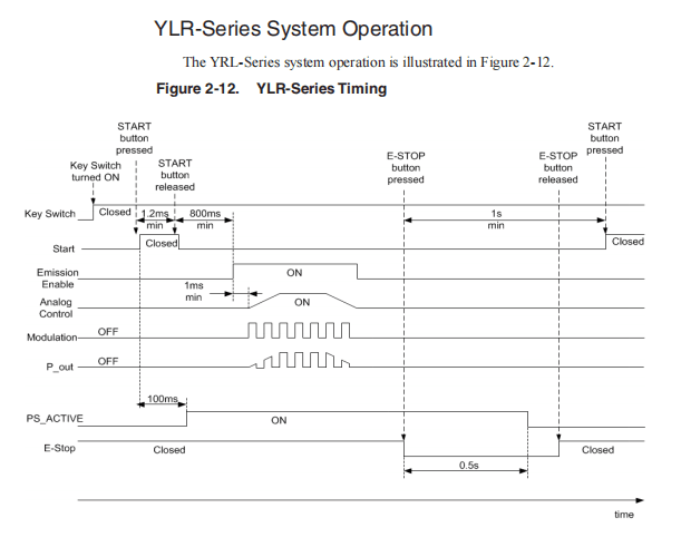
YLR-Series System Operation . . . . . . . . . . . . . . . . . . . . . . . . . . . 2-25
Rear Panel: 7-pin and 24-pin Connectors . . . . . . . . . . . . . . . . . . . 2-26
Operation Control Modes . . . . . . . . . . . . . . . . . . . . . . . . . . . . . . . 2-29
Turning on the Device in Local Control Mode . . . . . . . . . . . . . . . . 2-30
Turning on the Device in Remote Control Mode . . . . . . . . . . . . . . 2-30
Selecting Operation Modes . . . . . . . . . . . . . . . . . . . . . . . . . . . . . . 2-31
Pulse Mode (QCW) . . . . . . . . . . . . . . . . . . . . . . . . . . . . . . . . 2-31
Operational Sub-Modes . . . . . . . . . . . . . . . . . . . . . . . . . . . . . 2-32
Standalone Mode (Modulation and Gate control disabled) . . 2-32
Modulation Mode . . . . . . . . . . . . . . . . . . . . . . . . . . . . . . . . . . 2-32
Gate Mode . . . . . . . . . . . . . . . . . . . . . . . . . . . . . . . . . . . . . . . 2-32
External (Analog) Power Control . . . . . . . . . . . . . . . . . . . . . . 2-32
Pulse Shaper Program (Optional Feature) . . . . . . . . . . . . . . . 2-33
Using the Touch-Screen Display . . . . . . . . . . . . . . . . . . . . . . . . . . 2-33
3 Computer Interface/Commands
RS-232 Configuration . . . . . . . . . . . . . . . . . . . . . . . . . . . . . . . . . . . 3-1
Ethernet TCP/IP Interface . . . . . . . . . . . . . . . . . . . . . . . . . . . . . . . . 3-1
Interface Commands . . . . . . . . . . . . . . . . . . . . . . . . . . . . . . . . . . . . 3-2
4 Pulse Shaping
Overview . . . . . . . . . . . . . . . . . . . . . . . . . . . . . . . . . . . . . . . . . . . . . . . . 4-1
PC Requirements . . . . . . . . . . . . . . . . . . . . . . . . . . . . . . . . . . . . . . 4-2
Ethernet TCP/IP Interface . . . . . . . . . . . . . . . . . . . . . . . . . . . . . . . . 4-3
RS-232 Configuration . . . . . . . . . . . . . . . . . . . . . . . . . . . . . . . . . . . 4-3
Key Terms . . . . . . . . . . . . . . . . . . . . . . . . . . . . . . . . . . . . . . . . . . . . 4-3
Installing the Pulse Shaper Software . . . . . . . . . . . . . . . . . . . . . . . . 4-4
Configuring a Local Area Connection for Ethernet . . . . . . . . . . . . . 4-9
Pulse Shaper Configuration Procedures . . . . . . . . . . . . . . . . . . . . 4-12
Connecting using Ethernet . . . . . . . . . . . . . . . . . . . . . . . . . . . . . . 4-12
Connecting Using RS-232 . . . . . . . . . . . . . . . . . . . . . . . . . . . . . . . 4-13
Using the Offline Option . . . . . . . . . . . . . . . . . . . . . . . . . . . . . . . . 4-14
Exporting a Configuration . . . . . . . . . . . . . . . . . . . . . . . . . . . . 4-15
Importing a Configuration . . . . . . . . . . . . . . . . . . . . . . . . . . . . 4-15
Using the Pulse Shaper Program . . . . . . . . . . . . . . . . . . . . . . . . . . . 4-17
Laser Control Tab . . . . . . . . . . . . . . . . . . . . . . . . . . . . . . . . . . . . . 4-20
Shape Editor Tab . . . . . . . . . . . . . . . . . . . . . . . . . . . . . . . . . . . . . 4-21
Creating a New Pulse Shape Profile . . . . . . . . . . . . . . . . . . . . . . . 4-27
Creating a Single Pulse Shape . . . . . . . . . . . . . . . . . . . . . . . . . . . 4-28
Shifting a Pulse Shape . . . . . . . . . . . . . . . . . . . . . . . . . . . . . . . . . 4-29
Pulse Shape Storage and Recall . . . . . . . . . . . . . . . . . . . . . . . . . 4-30
On a Laser . . . . . . . . . . . . . . . . . . . . . . . . . . . . . . . . . . . . . . . 4-30
On a Host PC . . . . . . . . . . . . . . . . . . . . . . . . . . . . . . . . . . . . . 4-31
Deleting a Pulse Profile . . . . . . . . . . . . . . . . . . . . . . . . . . . . . 4-31
Single Pulse Activation . . . . . . . . . . . . . . . . . . . . . . . . . . . . . . . . . 4-33
Single Pulse Activation using the Touch-Display Screen . . . . . . . 4-34
Scaling Editor . . . . . . . . . . . . . . . . . . . . . . . . . . . . . . . . . . . . . . . . 4-35
Creating a New Pulse Scale . . . . . . . . . . . . . . . . . . . . . . . . . . . . . 4-36
Sequence Editor . . . . . . . . . . . . . . . . . . . . . . . . . . . . . . . . . . . . . . 4-37
Creating a New Pulse Sequence . . . . . . . . . . . . . . . . . . . . . . . . . 4-38
Building a Sequence . . . . . . . . . . . . . . . . . . . . . . . . . . . . . . . . . . . 4-39
Modifying a Pulse Sequence . . . . . . . . . . . . . . . . . . . . . . . . . . . . . 4-42
Pulse Sequence Storage and Recall . . . . . . . . . . . . . . . . . . . . . . 4-42
On a Laser . . . . . . . . . . . . . . . . . . . . . . . . . . . . . . . . . . . . . . . 4-42
On a Host PC . . . . . . . . . . . . . . . . . . . . . . . . . . . . . . . . . . . . . 4-43
Deleting a Pulse Sequence . . . . . . . . . . . . . . . . . . . . . . . . . . . . . . 4-43
Pulse Sequence Activation . . . . . . . . . . . . . . . . . . . . . . . . . . . . . . 4-45
Pulse Sequence Activation using the Touch-Screen Display . . . . 4-46
Remote Control Interface . . . . . . . . . . . . . . . . . . . . . . . . . . . . . . . 4-47
5 Troubleshooting
Error Messages on the Display and Status Bits . . . . . . . . . . . . . . . . 5-1
A Web User Utility
Overview . . . . . . . . . . . . . . . . . . . . . . . . . . . . . . . . . . . . . . . . . . . . . . . . A-1
Configuration Procedures . . . . . . . . . . . . . . . . . . . . . . . . . . . . . . . . . A-1
Configuring an Ethernet Connection . . . . . . . . . . . . . . . . . . . . . . . . A-1
Configuring an RS-232 Serial Connection . . . . . . . . . . . . . . . . . . . A-1
Configuring a LAN Connection for Ethernet . . . . . . . . . . . . . . . . . . . A-2
Website Data Settings . . . . . . . . . . . . . . . . . . . . . . . . . . . . . . . . . . . A-5
Accessing the Web User Utility . . . . . . . . . . . . . . . . . . . . . . . . . . . . A-7
B Service
Service and Repairs . . . . . . . . . . . . . . . . . . . . . . . . . . . . . . . . . . . . . . B-1
Serviceable Items . . . . . . . . . . . . . . . . . . . . . . . . . . . . . . . . . . . . . . . . B-1
Replacing Fuses . . . . . . . . . . . . . . . . . . . . . . . . . . . . . . . . . . . . . . . . . B-2
Replacing the Filter Media . . . . . . . . . . . . . . . . . . . . . . . . . . . . . . . . . B-2
C Optical Fiber Connector Inspection and Cleaning
Overview . . . . . . . . . . . . . . . . . . . . . . . . . . . . . . . . . . . . . . . . . . . . . . . . C-1
D Warranty
Limited Express Product Warranties . . . . . . . . . . . . . . . . . . . . . . . . . D-1
Warranty Limitations . . . . . . . . . . . . . . . . . . . . . . . . . . . . . . . . . . . . . . D-1
Limitation of Remedies and Liabilities . . . . . . . . . . . . . . . . . . . . . . . D-2
Software . . . . . . . . . . . . . . . . . . . . . . . . . . . . . . . . . . . . . . . . . . . . . . . . D-2
Firmware License Agreement . . . . . . . . . . . . . . . . . . . . . . . . . . . . . D-2
Software License Agreement for LaserNet™ . . . . . . . . . . . . . . . . . . D-6
IPG Laser GmbH® . . . . . . . . . . . . . . . . . . . . . . . . . . . . . . . . . . . . . D-6
Single Use License . . . . . . . . . . . . . . . . . . . . . . . . . . . . . . . . . . D-6
MICROSOFT CORPORATION EMBEDDED SOFTWARE
END USER LICENSE AGREEMENT . . . . . . . . . . . . . . . . . . . . . . . . . D-10
E Product Returns
Returns to the United States . . . . . . . . . . . . . . . . . . . . . . . . . . . . . . . E-1
Shipping Instructions: . . . . . . . . . . . . . . . . . . . . . . . . . . . . . . . . . . . E-2
Warranty Returns . . . . . . . . . . . . . . . . . . . . . . . . . . . . . . . . . . . E-2
Non-Warranty Returns . . . . . . . . . . . . . . . . . . . . . . . . . . . . . . . E-2
Returns to Germany . . . . . . . . . . . . . . . . . . . . . . . . . . . . . . . . . . . . . . E-3
F Glossary
. . . . . . . . . . . . . . . . . . . . . . . . . . . . . . . . . . . . . . . . . . . . . . . . . . . . . . . . F-1
1 Overview of the YLR-Series Fiber Lasers
Introduction
The IPG Photonics YLR-Series fiber lasers are developed to meet industrial market demands of efficient reliable maintenance-free high power lasers.
These lasers are a diode-pumped Ytterbium fiber laser with output powers ranging from 1W to 1.5 kW operating at the wavelength region of 1060-1100 nm.
The YLR-Series fiber lasers can be air or water-cooled. The wall plug efficiency for a fiber laser is typically exceeds 30 percent.
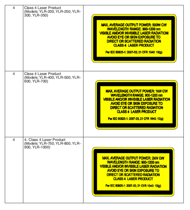
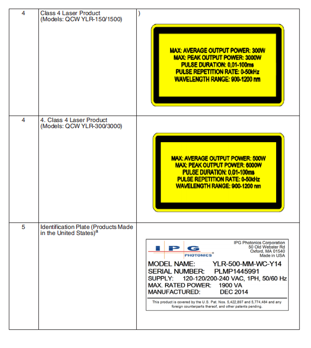
All YLR-Series fiber lasers are Class 4 laser products and are designed and tested with important safety features.
Follow this guide and apply laser safety practices for a safe and reliable device.
Laser light exhibits unique characteristics that pose safety hazards that are not normally associated with other light sources.
Therefore, all operators and other people near the laser must be aware of these special hazards.
Audience
The audience for this guide are system integrators and technicians responsible for installing and operating the IPG YLR-Series fiber lasers in industrial and non- industrial installations.
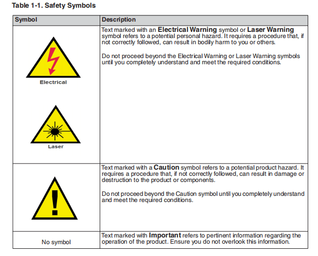
Safety Information and Conventions
To ensure the safe operation and optimal performance of the product, follow all warnings in this guide. Safety precautions must be observed during all phases of operation, maintenance, and service.
Operators must adhere to these recommendations and to apply sound laser safetypractices at all times. Never open the chassis.
There are no user serviceable parts,equipment or assemblies associated with this product. All internal service andmaintenance should only be performed by qualified IPG personnel.
Safety Features and Compliance toGovernment Requirements
Compliance to Regulatory Standards (on applicableunits)
EMC Emissions:
EN 55011:2009 + A1:2010
CISPR 11:2009 + A1:2010
FCC Class A
EMC Immunity:
EN 61000-3-2:2006+A1:2009+A2:2009
EN 61000-3-3:2008
EN 61326-1:2006
EN 61000-4-2:2009
EN 61000-4-3:2006 + A1:2007 + A2:2010
EN 61000-4-4:2004+A1:2010
EN 61000-4-5:2006
EN 61000-4-6:2009
EN 61000-4-8:2010
EN 61000-4-11:2004
EMC Other:
This Class A digital apparatus complies with Canadian ICES-003.
Electrical Safety:
61010-1:2010
Laser Safety:
EN 60825-1:2007
CDRH 21 CFR 1040.10
Functional Safety:
The following safety functions are implemented to fulfill the requirements of EN ISO 13849-1:2008 + A1:2009 Cat.3 / PL d and Category 3 (Cat. 3).
The safety functions are implemented exclusively in hardware:
- Stop initiated by a safeguard:The safety electronics of the laser monitors the feed fiber cable (optical fiber interlock). If the laser is emitting and the feed fiber is disconnected from a mating device or broken, the safety-related outputs become de-energized.
- Stop initiated by a safeguard:The safety electronics of the laser monitors E-Stop input. If the laser is emitting and the E-Stop is activated, the safety-related outputs become de-energized.
- Safe start/restart button:The safety electronics of the laser monitors safety-related outputs. A fault in the safety-related outputs is detected before the next demand upon the safety-related output.
- Dischargeof stored energy:The safety electronics of the laser monitors safety-related inputs. If the laser is emitting and a stop is initiated by a safeguard, the stored energy for the laser is discharged.
- Prevention of unexpected startup:The safety electronics of the laser monitors safety-related inputs. Start of restart cannot occur after activation of a safeguard until safeguard is re-established and separate deliberate action occurs.
Class A Digital Device
This equipment is tested and complies with the limits for a Class A digital device, pursuant to part 15 of the FCC Rules.
These limits are designed to provide reasonable protection against harmful interference when the equipment is operated in a commercial environment.
This equipment generates, uses, and can radiate radio frequency energy and, if not installed and used in accordance with this guide, can cause harmful interference to radio communications. Operation of this equipment in a residential area is likely to cause harmful interference in which case the users are required to correct the interference at their own expense.
Electromagnetic Compatibility
Compliance of the YLR-Series lasers with the EMC requirements is certified by theCE mark if identified by the CE label (Figure 1-1 on page 1-7).
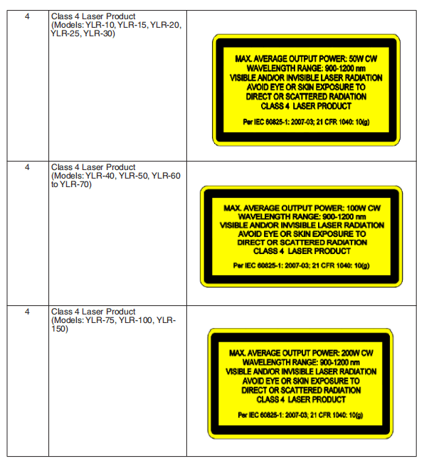
According to the European Community standards, this device is classified as Class
4 based on EN 60825-1, clause 9 This product emits invisible laser radiation at or
around a wavelength of 1070 nm, and the total light power radiated from the optical
output is greater than 20 to 1500 W (depending on model) per optical output port.
Direct or indirect exposure of this level of light intensity can cause damage to the
eye or skin. Despite the radiation being invisible, the beam can cause irreversible
damage to the retina and cornea.Appropriate and approved laser safety eyewear must
be worn at all times while the laser is operational.
WARNING: You must use appropriate laser safety eyewear when operating the device. The selection of appropriate laser safety eyewear requires that the end user accurately identify the range of wavelengths emitted from this product. If the device is a tunable laser or Raman product, it emits light over a range of wavelengths.
You must ensure that the laser safety eyewear used protects against light emitted by the device over its entire range of wavelengths.
Review the safety labeling on the product (see Figure 1-1 on page 17) and verify that the personal protective equipment
(for example, enclosures, viewing windows or viewports, garments, and eyewear) being used is adequate for the output power and wavelength ranges listed on the product.
Suppliers include LaserVision USA, Kentek Corporation and Rockwell LaserIndustries offer this laser safety material and equipment.
There are other laserpersonal protective equipment providers. IPG provides the names of theseproviders solely as a convenience and does not endorse or recommend any of them, or their products or services.
Furthermore, IPG assumes no liability forany of their recommendations, products, or services.
Whether the laser is used in a new installation or to retrofit an existing device,
the end user is solely responsible for determining the suitability of all personal protective equipment.
CAUTION: Do not install or terminate fibers or collimators when laser is active.
WARNING: Use of controls or adjustments, or performance of procedures
other than those specified herein, can result in hazardous radiation exposure.
CAUTION: Use of the device in a manner other than that described herein can
impair the protection provided by the device.
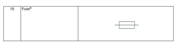
Safety Label Locations
The YLR Series Laser has the required laser safety labels located on the outside of the chassis in various locations.
These include warning labels indicating removable or displaceable of the protective housings, apertures through which laser radiation is emitted and labels of certification and identification.
Figure 1-1 shows the required laser safety labels and the locations for the Water-Cooled YLR-Series laser.
Figure 1-2 on page 1-7 shows the required laser safetylabels and the locations for the Air-Cooled YLR-Series laser.
These include warning labels indicating removable or displaceable protective housings, apertures through which laser radiation is emitted and labels of certification and identification.


- Refer to Table 2-1 on page 2-2 for Model Designation Codes.
- Refer to Table 2-1 on page 2-2 for Model Designation Codes.
- This symbol is specifically reserved for the PROTECTIVE CONDUCTOR TERMINAL and no other. It is placed at the equipment earthing point and is mandatory for all grounded equipment.
- This label indicates compliance with CE marking requirements.
- This symbol is accompanied with type and rating (for example, T15A, 250VAC, ¼ x 1-1/4).
Emission-On Indicator
The laser is equipped with a an Emission-On Indicator light located on the front panel(see Figure 2-1 on page 2-3). The Emission-On Indicator is turned on when laser emission is ready to emit.
If the laser aperture or a remote laser control is located more than two meters fromthe indicator on the front panel, then an additional indicator must be located at theaperture or remote control.
Emission ON, Pin 24 on the remote connector is active high when the laser is readyto emit. It can used to provide a laser-ready warning at the aperture or remote control when these are located two or more meters from the front panel.
General Safety Instructions

WARNING: You must exercise caution to avoid and minimize specular
reflections as these reflections occur at the laser’s wavelength and are invisible.
Specular Reflections
Often there can be numerous secondary laser beams produced at various angles nearthe laser aperture.
These beams are called “Specular Reflections” and are produced when the laser light reflects off a surface where the primary beam is incident.
Although these secondary beams might be less powerful than the total power emitted from the laser, the intensity might be great enough to cause damage to the eyes and skin as well as materials surrounding the laser.
Equipment and Solvents
Light-sensitive elements in equipment, such as video cameras, photomultipliers and
photodiodes can also be damaged from exposure to the laser light.
WARNING: The laser light is strong enough to cut or weld metal, burn skin, clothing, and paint.
In addition, this light can ignite volatile substances such as alcohol, gasoline, ether, and other solvents.
Exposure to solvents or other flammable materials and gases must be avoided and must be relocated away from this device.
Safety Recommendations
IPG recommends that you follow these procedures to operate the IPG laser safely:
- Never look directly into the laser output port when power is supplied to the laser.
- Avoid positioning the laser and all optical components at eye level.
- Provide enclosures for laser beam.
- Ensure that all personal protective equipment (PPE) is suitable for the output power and wavelength range listed on the laser safety labels that are affixed to the product.
- Usethe laser in a room with access controlled by door interlocks. Post warning signs. Limit access to the area to individuals who are trained in laser safety while operating the laser.
- Avoi dusing the laser in a darkened environment.
- Donot enable the laser without a coupling fiber or equivalent attached to the optical output connector.
- Alwaysswitch the laser off when working with the output such as mounting the fiber or collimator into a fixture. If necessary, align the output at low output power and then increase the output power gradually.
- Do not install or terminate fibers or collimators when laser is active.
- If this instrument is used in amanner not specified in this document, the protection provided by the instrument may be impaired and the warranty will be voided.

Optical Safety
CAUTION: If the output of the device is delivered through a lens with an anti-
reflection coating, ensure that the lens is of good quality and clean. For cleaning
instructions, refer to “Optical Fiber Connector Inspection and Cleaning” on
page C-1.
Any dust on the end of the collimator assembly can burn the lens and damage
the laser.
Hot or molten pieces of metal can be present when using this laser. Exercise
caution if debris is being generated in your application.
Electrical Safety
WARNING: The input voltage to the laser is potentially lethal. All electrical
cables and connections should be treated as if it were a harmful level. All parts
of the electrical cable, connector, or device housing should be considered
dangerous.
To ensure electrical safety:
1. Make sure the device is properly grounded through the protective conductor of
the AC power cable. Any interruption of the protective grounding conductor
from the protective earth terminal can result in personal injury.
2. Always use your device in conjunction with properly grounded power source.
3. For continued protection against fire hazard, replace the line fuses (if
applicable) with only the same types and ratings. The use of other fuses or
material is prohibited.
4. Before supplying the power to the instrument, ensure that the correct voltage
of the AC power source is used. Failure to use the correct voltage can cause
damage to the instrument.
5. Before switching the power on, ensure that line voltage corresponds to the
specified level.
6. There are no operator serviceable parts inside. Refer all servicing to qualified
IPG personnel. To prevent electrical shock, do not remove covers. Any
tampering with the product voids the warranty.
Environmental Safety
WARNING: Never look directly into a laser aperture (such as fiber, collimator, or scanning head) when the Start button or remote Start circuit is activated. Ensure that you wear appropriate laser safety eyewear at all times while operating the product.
Proper enclosures must be used to secure a laser safe work area. This includes but isnot limited to laser safety signs, interlocks, appropriate warning devices and training/safety procedures.
In addition, it is important to install the output assembly away from eye level.
WARNING: Ensure that all personal protective equipment (PPE) is suitable for the output power and wavelength range listed on the laser safety
labels that are affixed to the product.
The interaction between the laser and the material being processed can also generate high intensity UV and visible radiation.
Ensure that all laser enclosures are in place to prevent to prevent eye and skin exposure to visible and invisible collateral radiation.

CAUTION: Damage to the laser is possible, unless caution is employed inoperating the device.
IPG provides the following recommendations to promote the long life of the IPG laser:
- Do not expose the device to a high moisture environment (>95% humidity).

CAUTION: Water-cooled lasers must not operate at temperatures below the respective ambient dewpoint (see Table 1-3 on page 1-17).
- The device might have fans for active cooling. Ensure there is sufficient airflow tocool the device. Any objects or debris that cover the ventilation holes must be inspected. Filter media should be inspected at regular intervals to maintain sufficient airflow into the device.
- Operation at higher temperatures accelerate aging, increase threshold current, and lower slope efficiency. If the device is overheated, do not use it and call IPG for assistance.
- Ensure that the work area is properly vented. gases, sparks and debris that can be generated from interaction between the laser and the work surface can pose additional safety hazards.
- Inspect the filter media weekly and clean or replace as needed. See “Replacingthe Filter Media” on page B-2 for details.
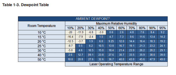
1 These values are calculated using the August-Roche-Magnus approximation.
Additional Safety Resources
For additional information regarding Laser Safety, refer to the following list:
Laser Institute of America (LIA)13501 Ingenuity Drive, Suite 128Orlando, Florida 32826
Phone: 407.380.1553, Fax: 407.380.5588Toll Free: 1.800.34.LASER
American National Standards InstituteANSI Z136.1, American National Standard for the Safe Use of Lasers (Available through LIA)
International Electro-technical Commission IEC 60825-1, Edition 2 Safety of laser products –
Part 1: Equipment classification, requirements and user’s guide.(Available through LIA)
Center for Devices and Radiological Health
21 CFR 1040.10 – Performance Standards for Light-Emitting ProductsUS Department of Labor – OSHA
Publication 8-1.7 – Guidelines for Laser Safety and Hazard Assessment
US Department of Labor – OSHA
Publication 8-1.7 – Guidelines for Laser Safety and Hazard Assessment
Laser Safety Equipment Laurin Publishing
Laser safety equipment and Buyer’s Guides

IPG Photonics recommends that the user of this product investigate any or country requirements as well as facility or building requirements that to installing or using a laser or laser device.
Ensure that the standard you are using such as ANSI, IEC, and OSHA are current.
2 Using Your Device
Overview
The IPG Photonics YLR-Series fiber lasers are developed for use in industrial applications.
The lasers are compact and efficient letting you replace bulky and less efficient lasers. Main application are welding, cutting, and brazing.
Main Features
- High quality fiber output
- High power
- Reliable, long lifetime
- Compact, rugged package
- Efficient
- External computer interface
Applications
- Industrial applications
- Scientific research
Model Configurations
IPG offers manyYLR-Series configuration models.This guide is designed to provide complete instructions for all models.
Therefore, specific difference in models is noted where applicable.
Laser Model Designation Codes
Figure 2-1 on page 2-2 shows the model designation methodology for all YLR-Series lasers.
In addition, models are also categorized according to chassis type with their respective “U” or Rack Unit code.
The subsequent AC or WC code designates whether the model is air cooled or water cooled.
The U categories offered are 3U-AC, 3U-WC, 4U-AC, 4U-WC, and 6U-AC.

Table 2-1. Laser Model Designation Codes
| Number | Item | Code |
| 1 | YLR | Ytterbium Laser 19-inch Rack Mount |
| 2 | Power in W | Range of 20 to 1500 Watts |
| 3 | Wavelength in nm | Item is listed if wavelength is not standard. 1070 nm (standard) |
| 4 | Polarization/Output Beam Characteristic | MM — for Multi-Mode LP — for Linearly Polarized If an item is not listed, then the beam is single-mode and randomly polarized. |
| 5 | Additional Information | WC — Water Cooled device AC — Air Cooled device |
| 6 | Additional Information | The last two digits of the model year, |
Table 2-2. Available YLR Series Models
| Category | Model |
| 3U-AC | YLR-20, YLR-30, YLR-50, and YLR-100-AC |
| 3U-WC | YLR-100-WC, YLR-200-WC, YLR-300-WC, YLR-400-WC, YLR-500-WC, YLR-600-WC, and YLR-700-WC |
| 4U-AC | YLR-200-AC, YLR-300-AC, YLR-400-AC, and YLR-150/1500-QCW-AC |
| 4U-WC | YLR-1000-WC |
| 6U-AC | YLR-500-AC and YLR-600-AC |
Certification
IPG Photonics certifies that your system is thoroughly tested and inspected and meets published specifications prior to shipping.
Upon receiving your device, check thepackaging and parts for any possible damage that might have occurred in transit.
If there is damage, contact IPG Photonics immediately. It is the responsibility of the purchaser/end-user to bring the end system into compliance with all applicable regulations.
YLR Series — Front Panel View
The YRL Series front panel includes two options: panel with a display and panel without a display.
Figure 2-2 shows the front panel of the YLR-Series, which includes an option witha display. Table 2-3 lists details for each component.
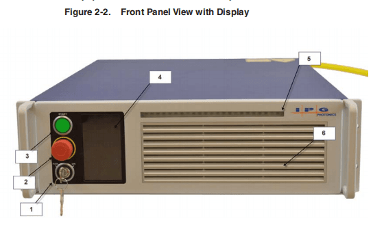
Table 2-3. Front Panel Descriptions
| Item | Feature | Description |
| 1 | Keyswitch (Local Interface option only) | The 3-position key switch controls the laser operation mode: Left position — Chassis Powered On, Remote Control Mode Central position — Chassis powered Off Right position — Chassis Powered On, Local Control Mode Note: The key cannot be removed in the Remote Control Mode or Local Control Mode positions. |
| 2 | Emergency Stop Button (E-Stop) (Local Interface option only) | Temporarily suspends power to the laser module. When active, the main DC power supply is disabled. You can reset it by turning clockwise. |
| 3 | Start Button with Indicator (Local interface option only) | When pressed, turns On the internal main power supply of the laser assuming that the Power key is in the Local Mode position. When the indicator is On, the internal power supply is active and the laser is capable of producing laser radiation. |
| 4 | Touch-Screen Display (Local interface option only) | Use to set device settings and to display measured parameters and alarm messages. |
| 5 | Emission On Indicator | ocal Control Mode: The indicator blinks for a short period after emission is enabled and before laser radiation is emitted. once laser emission is ON, the indicator is in the steady state “ON.” |
| 6 | Front Bezel Panel | Remote Control Mode: The indicator is lit once emission is enabled. Pull on each side to filter element for cleaning or replacement. Refer to Table B-1 on page B-2 for more information. |
Figure 2-3 shows the front panel of the YLR-Series, which does not include a display.
Table 2-4 lists details for each component.

| Item | Feature | Description |
| 1 | Power | When lit, indicates that internal main power supply of the laser is on. When the indicator is on, the internal power supply is active and the laser is capable of producing laser radiation. |
| 2 | PS Active | When lit, indicates that the main supply voltage is applied to the laser module inside the device. |
| 3 | Emission | When lit, indicates that the emission is activated. |
| 4 | Error | When lit, indicates an device error, such as a interlock door is open. |
| 5 | Front Bezel Panel | Pull on each side to filter element for cleaning or replacement. Refer to Table B-1 on page B-2 for more information. |
YLR Series — Rear Panel View
The YLR-Series is available as a Water-Cooled (WC) or Air-Cooled (AC) laser.
Figure 2-5 shows details of the rear panel of the YLR-Series WC laser. Table 2-4lists details for each component.
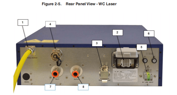
Table 2-4. Rear Panel Descriptions
| Item | Feature | Description |
| 1 | Laser Output | The output of the laser (fiber cable) is delivered through this location. |
| 2 | Hardwiring Interface (24-pin) | The 24-pin connector provides an analog and digital interface for hardwiring control of the laser. See Table 2-5 on page 2-14 for detailed information. |
| 3 | Hardwiring Interface (7-pin) | The 7-pin connector provides status of the power supply and front panel Emergency Stop (if present). See Table 2-8 on page 2-23 for detailed information. |
| 4 | Ethernet | Ethernet port |
| 5 | AC line input | The 3-pin screw terminal connector for AC input wiring. Refer to the SPECIFICATION YTTERBIUM FIBER LASER document included with this product to determine your models power requirement. |
| 6 | AC line fuses | Replaceable fuses F1, F2 Refer to Table B-1 on page B-2 for more information. |
| 7 | Coolant Inlet | Liquid Coolant Input Refer to the SPECIFICATION YTTERBIUM FIBER LASER document included with this product for coolant details. |
| 8 | Coolant Outlet | Liquid Coolant Output Refer to the SPECIFICATION YTTERBIUM FIBER LASER document included with this product for coolant details. |
| 9 | Drain | Drain for the dehumidifier option. |
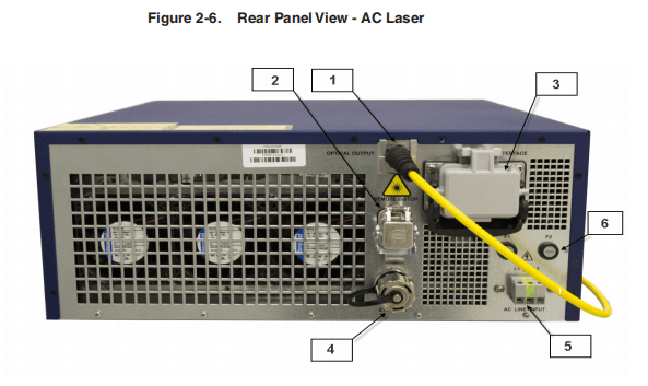
Table 2-5. Rear Panel Descriptions
| Item | Feature | Description |
| 1 | Laser Output | The output of the laser (fiber cable) is delivered through this location. |
| 2 | Hardwiring Interface (24-pin) | The 7-pin connector provides status of the power supply and front panel Emergency Stop (if present). See Table 2-8 on page 2-23 for detailed information. |
| 3 | Hardwiring Interface (7-pin) | The 24-pin connector provides an analog and digital interface for hardwiring control of the laser. See Table 2-5 on page 2-14 for detailed information. |
| 4 | Ethernet | Ethernet port |
| 5 | AC line input | The 3-pin screw terminal connector for AC input wiring. Refer to the SPECIFICATION YTTERBIUM FIBER LASER document included with this product to determine your models power requirement. |
| 6 | AC line fuses | Replaceable fuses F1, F2 Refer to Table B-1 on page B-2 for more information. |
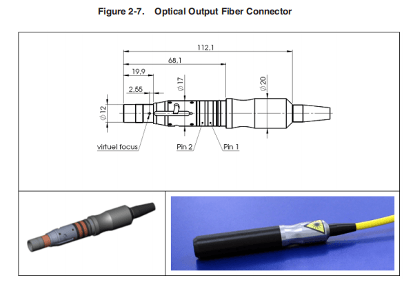
Optical Output Fiber Terminations
Products with a Connector
The end connector of the fiber (as shown in Figure 2-7) uses a protective cap that covers and protects the optical surface and electrical contacts when not in use.
These protective caps must be removed from the connectors when connecting the process fiber cable of the laser to an appropriate optical interface.
You should remove the protective caps from the connectors immediately before optical cleaning and mounting in an adapter.
Products with a Collimator
Collimators have a protective window that can be replaced if damaged (as shown inFigure 2-8).
You must remove the collimator end cap prior to use. This cap can be reused when storing the system.
Cleaning of the protective window should be performed as needed using the same materials and techniques described in “Optical Fiber Connector Inspection and Cleaning” on page C-1.

Model Specifications
Because theYLR-Series product line is extensive, all specifications for your specificmodel are listed in the supplemental document titled SPECIFICATION YTTERBIUMFIBER LASER included with the product.
These specifications include:
- Optical
- Electrical
- Environmental
- External Layout and Dimensions
Unpacking Instructions

If the packaging shows any signs of external damage, check unit for damages and
notify the shipping agent immediately.
Particular care must be taken when you remove the unit from the packing case to
ensure that the fiber optic cable is not broken or damaged.A comprehensive packing
list is included with the system documentation.
Upon receipt of the laser, check all items against this list and contact IPG immediately
if any of the items are missing or if any damage to the unit is evident. If any damage
to the unit is evident or suspected, do not attempt to install or operate the laser in any
case.
CAUTION: Lift and carry the device by supporting the device from the base.
Use the handles (if available for your device) to help position the product while it is properly supported.
Do not use the handles for lifting or carrying the device.Do not lift or position the device by any attached fibers or cables.
Laser models that are smaller and relatively lighter are packaged in foam insulatedcardboard boxes.
See “Unpacking a Unit from a Cardboard Box” on page 2-11.
Laser models that are larger and relatively heavy are packaged in foam insulatedwooden crates. See “Unpacking a Unit from a Wooden Crates” on page 2-14.
To minimize the risk of damage to your system, IPG Photonics recommends that you unpack your laser using the following procedures.
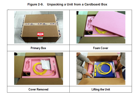
Unpacking a Unit from a Cardboard Box
See Figure 2-9 on page 2-13 for an illustration of this procedure.
To unpack your unit from a cardboard box:
- Place the package on astable surface such as the floor or a large table.
- For international shipments, remove the external box to access the primary box.
- Open the primary box and remove the foam cover and store for later use.
- Place the fiber on top of the unit and carefully lift it out of the box. IPG strongly recommends two people to lift the unit at all times.
- Open the internal box and remove the top foam insert.
- Check the inventory of following items:
Retain all packaging for future transportation or storage needs.
| Shipping Box Contents | Quantity |
| Cover,AC power inlet(P45-001394) | 1 |
| Strain Relief(P40-002294) | 1 |
| Strain Relief Nut(P40-002293) | 1 |
| Harting 24-pin Interface Connector Kit(P30-007268) | 1 |
| Connector(p40-001344) | 1 |
| Hood(P40-001344) | 1 |
| Cable Seal(P40-000891) | 1 |
| Contact Pins(P40-000888) | 16 |
| Contact Pins(P40-000887) | 10 |
| Keys | 2 |
| Harting 7-pins Interface Connector(P30-007305) | 1 |
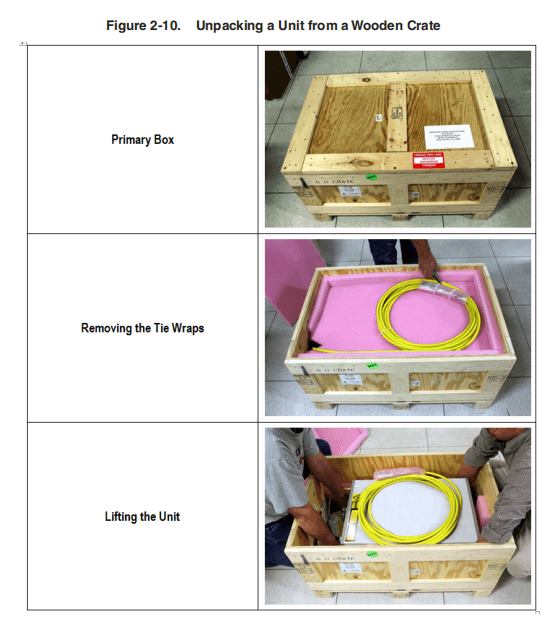
Unpacking a Unit from a Wooden Crates
See Figure 2-10 on page 2-15 for an illustration of this procedure.
To unpack a unit from a wooden crate:
- Place the package on a stable surface such as the floor or a large table. IPG recommends using a powered screw driver to remove all of the top screws securing the top lid.
- Remove the top lid and top foam insert.
- Using a cutting tool remove the tie wraps securing the fiber to the second insert.
- Place the fiber on top of the unit and carefully lift it out of the box. IPG strongly recommends two people to lift the unit at all times.
- Check the inventory of following items:
- Retain all packaging for future transportation or storage needs
| Shipping Box Contents | Quantity |
| Cover,AC power inlet(P45-001394) | 1 |
| Strain Relief(P40-002294) | 1 |
| Strain Relief Nut(P40-002293) | 1 |
| Harting 24-pin Interface Connector Kit(P30-007268) | 1 |
| Connector(p40-001344) | 1 |
| Hood(P40-001344) | 1 |
| Cable Seal(P40-000891) | 1 |
| Contact Pins(P40-000888) | 16 |
| Contact Pins(P40-000887) | 10 |
| Keys | 2 |
| Harting 7-pins Interface Connector(P30-007305) | 1 |
Using the YLR-Series

CAUTION: Refer to the SPECIFICATION YTTERBIUM FIBER LASER document included with this product for proper electrical power requirements.
Before switching the power on, ensure that the incoming AC voltage is equal to
the level noted in the specification.
Operate only in an environment with sufficient airflow capacity that allows for
the specified heat load developed during operation.
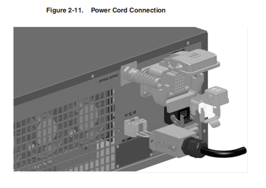
Connecting Electrical Power
Refer to the SPECIFICATION YTTERBIUM FIBER LASER document included with this product to determine your models power requirements.

A power cord is not provided with the laser.
To connect the electrical power:
- Wire the power input terminal block on the rear panel of the laser to the voltage, phase and frequency indicated on the SPECIFICATION YTTERBIUM FIBER LASER document for your particular model.
L2 = Line Voltage, PE = Protective Earth, L1 = Line Voltage
- Cover the input power terminal block with the supplied cover.
- Secure the cable with the supplied strain relief.
The electrical connection to the unit must be permanently connected to dedicated AC mains with a circuit breaker that does not exceed 20 Amps.
This must be in close proximity to the unit and within easy reach of the operator and marked as the disconnecting device for the unit.
- Follow all national and local requirements when wiring to the unit.
Interface Wire Specification
The minimum wire gage is 18AWG at 15 meters (30 meters maximum regardless of gauge).The gage of the wire must increase as the distance increases. For connectivity, the wiring and/or cabling must have an overall shield to ensure proper functionality.The shield is to cover over all conductors and terminate at the unit where the conductors enter/exit the unit.
Connections to External Circuits
Except for Mains connection, the external connections between this product and otherexternal devices are PELV (Protected Extra Low Voltage) as defined by IEC 61140.Non-Mains outputs of other devices connected to this product should also be PELVor SELV (Safety Extra Low Voltage).
Interlock Safety Circuit
YLR lasers include an Interlock Safety Circuit that uses a dual-channel system with monitored output and manual reset.
When you open the Interlock, the safety circuit opens and power to the laser diodes is removed.
Follow these steps:
- Closethe dual channel interlock (on 24-pin connector: pin1 is connected with pin4 and pin2 is connected with pin3). Otherwise, the internal main power supply is switched off and the emission cannot be turned on.
Once any of the pairs of the mentioned above contacts is opened, you cannot switch the lasers power supply on until the second pair is opened and then both pairs are closed.
- If you close the interlock (the Emergency Stop button is also released) and a fault is not detected, press the Start button to connect the remote start contacts, which enables the main power supply. The Power Supply (PS) Active signal enters a high state and power is supplied to the laser module. The laser diodes remain inactive until a separate Laser Enable signal transitions high and an output power level set to a non-zero value.
The power to the laser diodes also turns on. However, under normal conditions the diodes only turn on after emission is enabled.
When you open the interlock or a fault is detected, the laser diodes are discon- nected from the main power supply. The Power Supply Active signal enters a low state.
A detected fault is latched and circuits open the monitored manual reset loop, thus preventing the laser from being restarted until the fault is addressed. If a fault is detected, such as a shorted interlock channel, or a shorted Start button, the safety circuit does not reset until the fault is corrected.
If the remote Start button is shorted (this is the equivalent of holding in the Startbutton), the circuit does not reset when the interlocks are closed until the safety circuit processes both channels open and then closed or the power to the safetycircuit is cycled (with the Start button in the opened state in both cases).
Interface Connector Pin Assignments
Table 2-6. 24-Pin Connector Pinouts
| Pin | Signal Name | Signal Type | Signal Level | Signal Drive | Typical Response Time | Description |
| 1 | Interlock Ch1A | Contact Closurea to pin 4 | – | – | < 500 ms CW <1.2 s QCW | Emergency Shutdown according to ISO 13849-1 Cat.3 PL d.b |
| 2 | Interlock Ch2A | Contact Closurea to pin 3 | ||||
| 3 | Interlock Ch2B | ContactClosurea to pin 2 | ||||
| 4 | Interlock Ch1B | ContactClosure to pin 1 | ||||
| 5 | RS232 Tx | Serial Communication | – | – | 120 ms | Transmit Data |
| 6 | RS232 Rx | Serial Communication | – | – | Receive Data | |
| 7 | RS232 Com | Return | – | – | RS-232 Return | |
| 8 | Remote Key Switch | Contact Closurea | – | – | 5 s | Activates the laser control electronics in Remote |
| 9 | – | – | ||||
| 10 | Remote Start Button | Momentary Contact Closure | – | – | 1 s | Activates the internal main power supply and connects it to the laser module in Remote mode. |
| 11 | ||||||
| 12 | Analog Input to Control Current | Analog Input | 1-10 VDC | 1 mA (sink) | 20 µs | Analog Input 1-10 VDC = 10 – 100% Setpoint |
| 13 | Analog Output Power Monitor | Analog Output | 0-5 VDC | 11 mA (source) | 20 µs | Analog Output 0-4 VDC = 0 |
| 14 | Isolated Analog Com | Return | – | – | – | Return for signals on pins 12, 13. |
| 15 | Modulation + | Digital Input | 5 to 24 VDC | 6 mA (sink) | 20 µs | 5 -24 VDC Input. |
| 16 | Modulation – | Return | – | – | Return for signal on pin 15. | |
| 17 | Guide Control | Digital Input | 5 to 24 VDC | 6 mA (sink) | 120ms | Positive edge turns On red guide laser in Remote Control Mode. |
| 18 | Emission Enable | Digital Input | 5 to 24 VDC | 6 mA (sink) | 120ms | Positive edge activates emission in Remote Control Mode. |
| 19 | Error/Ready | Digital Output | 24 VDC | 100 | 120 ms | Low indicates a laser error. |
| 20 | System Common | Return | – | – | – | Returnforsignalsonpins17-19,21-24. |
| 21 | Error Reset | Digital Input | 5 to 24 VDC | 6 mA (sink) | 120 ms | Positive edge resets all resettable errors. |
| 22 | Power On | Digital Output | 24 VDC | 100 mA | 120 ms | High indicates that key switch is turned on. |
| 23 | Power Supply Active | Digital Output | 24 VDC | 100 mA | 120 ms | High indicates that the internal main power supply is active. |
| 24 | Emission ON | Digital Output | 24 VDC | 100 mA | 120 ms | High at the emission is enabled. |
- Connection of potential free contacts only. External contact closure must be rated to > 1A /24 VDC.
- To have a possibility of the internal main power supply activation, it is necessary to close the dual channel interlock (pin1 is connected with pin4 and pin2 is connected with pin3). Otherwise, the internal main power supply is switched off and the emission cannot be turned on. Once either of these connection pairs is opened, it is impossible to switch the lasers power supply on until the second pair is opened and then both pairs are closed.
- Touse this pin, external guide beam control must be enabled (EEABC command).
- Touse this pin, external emission control must be enabled (ELE command).
Note: Connector housing is EMC rated and is the intended connection point for the shielding of the customer’s cabling.
Table 2-7. 24-Pin Connector — Additional Details
| Pin | Signal Name | Description |
| 1 | Interlock Ch1A | These connections are intended to satisfy the Remote Interlock Connector requirement as defined by 21 CFR 1040.10 (f)(3) and IEC 60825-1 (4.4). If the connections between pins 1-4 or 2-3 are breeched by a door interlock or other means, laser emission is prevented. |
| 2 | Interlock Ch2A | |
| 3 | Interlock Ch2B | |
| 4 | Interlock Ch1B | |
| 5 | RS232 Tx | – |
| 6 | RS232 Rx | |
| 7 | RS232 Com | – |
| 8 | Remote Key Switch | Intended for use when the laser product is integrated into an end-user system. It is the responsibility of the purchaser/end-user to bring the end system into full compliance with all applicable regulations. |
| 9 | ||
| 10 | Remote Start Button | Intended for use when the laser product is integrated into an end-user system. It is the responsibility of the purchaser/end-user to bring the end system into full compliance with all applicable regulations. |
| 11 | ||
| 12 | Analog Input to Control Current | Intended to control the level of laser output power with either Local or Remote Control Mode enabled, power supply enabled, external emission control enabled (Remote Control Mode only), and analog control enabled.The output power is proportional to the analog voltage being supplied to the device. IPG recommends the integrator sets the voltage on this pin to zero volts when the emission, laser power supply, or the laser main power (VAC) is OFF. IPG also recommends the integrator use a analog voltage source capable of supplying a clean/stable signal. Suggested voltage sources might be in the form of a PLC, Arbitrary Waveform Generator, or other similar products. |
| 13 | Analog Output Power Monitor | – |
| 14 | Isolated Analog Com | – |
| 15 | Modulation + | Modulation mode must be enabled and can be used in either Local or Remote Control modes of operation. Review the product specification for allowable modulation settings specific to your product. Also, the modulation signal is not intended to be used for functional safety or as a safety device. IPG has incorporated a certified safety circuit for this purpose and it is the responsibility of the purchaser/end-user to bring the end system into full compliance with all applicable regulations. |
| 16 | Modulation – | – |
| 17 | Guide Control | – |
| 18 | Emission Enable | Intended to control the level of laser output power with Remote Control Mode enabled, power supply enabled, and external emission control enabled. The emission enable signal is not intended to be used for functional safety or as a safety device. IPG has incorporated a certified safety circuit for this purpose and it is the responsibility of the purchaser/end-user to bring the end system into full compliance with all applicable regulations. Hardware Control must be set to enable in the laser web interface. |
| 19 | Error/Ready | – |
| 20 | System Common | – |
| 21 | Error Reset | – |
| 22 | Power On | Intended to be used by the integrator for indicating the laser control system is turned ON. The signal is active high when the local key is turned on or when the remote key is turned on for models without the display option. If Local Control Mode is ON or in the middle position and the remote key is ON, the control system is OFF. The integrator should use this signal to notify operators using the end product, that the key has been turned on. It is the responsibility of the purchaser/end-user to bring the end system into full compliance with all applicable regulations. |
| 23 | Power Supply Active | Intended to be used by the integrator for indicating the power supply is activated. The signal is available whether the laser is in Local Control or Remote Control Mode.The integrator should use this signal to warn operators using the end product that the power supply is active and the laser is capable of emitting laser radition.Since the laser emission is delivered through an optical cable which might be tens of meters in length. This signal is provided so proper warnings are made available at the laser aperture and the remote control system as defined by the integrator. It is the responsibility of the purchaser/end-user to bring the end system into full compliance with all applicable regulations. |
| 24 | Emission ON | Intended to be used by the integrator for indicating the laser emission is turned ON. The signal is available whether the laser is in local or remote mode. The integrator should use this signal to warn operators using the end product that emission is turned ON and the product can be or is emitting laser radiation. Since the laser emission is delivered through an optical cable which might be tens of meters in length, this signal is provided so proper warnings are made available at the laser aperture and remote control system as defined by the integration. Note:The signal is active when the emission is turned ON and remains active even if the laser output is set at “zero” and no actual laser emission is present. It is the responsibility of the purchaser/end-user to bring the end system into full compliance with all applicable regulations. |
Table 2-8. 7-Pin Connector Pinouts
| Pin | Signal Name | Signal Type | Signal Level | Signal Drive | Typical Response Time | Description/Comments |
| 1 | E-Stop Out Channel 3A | Contact Closure to pin 3a | Direct connection to E-Stop button on the front panel. If you press Emergency Stop on the front panel, channels 3 and 4 are open. Intended to be used by integrators to shut down parts of the system or entire system when the laser front panel E- stop is activated. Only applicable to laser option with display and controls on the front panel. | |||
| 2 | E-Stop Out Channel 4A | Contact Closure to pin 4a | ||||
| 3 | E-Stop Out Channel 3B | Contact Closure to pin 1a | ||||
| 4 | E-Stop Out Channel 4B | Contact Closure to pin 2a | ||||
| 5 | PS_Active1 | Digital Output | 24 VDC | <100mA (source) | 120 msb | Redundant signal for indicating the power supply has been activated.The signal is available whether the laser is in Local Control or Remote Control Mode. The integrator should use this signal to warn operators using the end product, that the power supply is active and capable of emitting laser radiation. It is the responsibility of the purchaser/ end-user to bring the end system into full compliance with all applicable regulations. |
| 6 | No Connection | – | – | – | – | |
| 7 | Common | Return | – | – | – | Return for signals on pins 5. |
- Contact closure components rated 24VDC, 1A.
- Interlock response time (500 ms and 1.2s QCW models) must be additionally considered to ensure the safe state of the device.
Note: Connector housing is EMC rated and is the intended connection point for the shielding for the customer’s cabling.
Initial Power-Up Sequence
CAUTION:All electrical connections (and water connections for Water-Cooledmodels) must be connected prior to applying power to the unit.
In addition and where applicable, all connections must be secured with screws to ensure proper functionality.
To initially power-up the system:
1. Ensure the E-Stop button on the front panel is pushed in.
2. Inspect the optical output end face to check for dust and debris (refer to “Optical
Fiber Connector Inspection and Cleaning” on page C-1 for more information).
3. Properly align the output fiber into the delivery optics.
4. Properly secure optical output collimator.
WARNING: Never look directly into a live fiber and ensure that you wear appropriate laser safety eyewear at all times while operating the product.
Ensure all power is removed from the laser when handling the delivery cable.
- Ensure the Interlock (pins 1to 4, 2 to 3) on the interface connector is closed.
- Release (pull out) the E-Stop button on the front panel and ensure that the external E-Stop (from the 24-pin connector) is disengaged if used.
- Ensure that the air-cooling vents are unobstructed to allow proper cooling of the device.
- Verify that the external cooling unit is powered on (for Water-Cooled models only).
Key Control
You cannot turn on or operate the device until the key switch is in the ON or REMposition. ON or REM is only applicable to products with the Local Control option.Products that do not have this option need to close the remote key circuit, pins 8 and 9 on remote connector (refer to Table 2-6 on page 2-19).
You cannot switch between ON and REM without moving position into OFF and then waiting a few seconds.
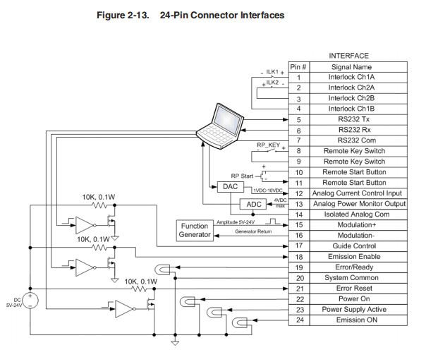
Rear Panel: 7-pin and 24-pin Connectors
There are two connectors on the rear panel of chassis: 7-pin and 24-pin. Figure 2-13 on page 2-27 shows the connections to 24-pin connector.
Figure 2-14 on page 2-28 shows the connections to the 8-pin connector.
The two Interlock contacts ILK1 and ILK2 are connected between pins 1-4 and 2-3.
The Keyswitch is connected between pins 8 and 9. This switch should be closed to power system up in Remote Control Mode.
The Start button is connected between pins 10 and 11. When closed it starts system in Remote Control Mode.
There is an isolated RS-232 interface (signals on pins 5 and 6 are referenced to return on pin 7). Two isolated analog signals on pins 12 and 13 are referenced to analog return on pin 14. Two differential modulation signals on pins 15 and 16 are also isolated. The control and diagnostic signals on pins 17-19 and pins 21-24 are referenced to return on pin 20 and are isolated.
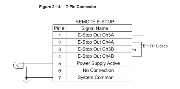
Two contacts of the E-Stop button are connected between pins 1-4 and 2-3. When you push the E-Stop button, these contacts become open.
They return to closed state when E-Stop button is released.
One isolated Power Supply Active signal on pins 5 is referenced to the return onpin 7.
Operation Control Modes
There are two control modes for the laser: Local and Remote. You select these modesusing the Keyswitch on the front panel (see Figure 2-2 on page 2-3).
If the Keyswitch is in the ON position, the Local control mode is activated. If the Keyswitch is in REM position, the Remote control mode is activated.
Table 2-9 details the differences between these two modes:

Turning on the Device in Local Control Mode
To turn on the device in Local Control Mode:
- Turn the front panel Keyswitch clockwise to the ON position.
- Press the Start button to turn on the main power supply.
- Wait until the laser becomes active.
The laser is now ready for operation. You can now select a proper operation mode.
Turning on the Device in Remote Control Mode
To turn on the device in Remote Control Mode:
- Turn the front panel Keyswitch counterclockwise to the REM position.
- Close contact pins eight and nine to provide the remote keyswitch function.
- Make momentary closure of pins 10 and 11 to activate the main power supply.
- Turn the emission on. Refer to “Local and Remote Control Modes” on page 2-29.
- Wait until the laser becomes active.
The laser is now ready for operation. You can now select a proper operation mode.
Selecting Operation Modes
In both control modes (Local and Remote), there are two main modes of laser emission:
- Continuous (CW)
- Pulsed (QCW)
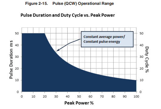
Pulse Mode (QCW)
Pulse Mode (for QCW models only, Pulse-mode enabled) laser internally generates a sequence of pulses. Pulse duration and pulse repetition rate can be configured by:
- Sending corresponding commands via RS-232 interface, or•Using the Pulse Settings submenu on the touchscreen display
The main difference between Pulse and CW modes is that in Pulse Mode the maximum peak power is considerably higher than in CW.
However, the maximum pulse duration and the maximum duty cycle are limited to certain values (refer to the SPECIFICATION YTTERBIUM FIBER LASER documentand refer to Figure 2-15).
When in CW mode, the maximum pulse duration and duty cycle are not applicable.
Operational Sub-Modes
For each mode of laser emission (Continuous or Pulse), there are four operational sub-modes:
- Standalone
- Modulation
- Gate
- External (Analog) Power Control
The main difference between sub-modes of operation is how the laser power is set and the laser emission is switched on/off.
Continuous Mode (Pulse mode is disabled) laser generates CW emission (except forGate mode).
Standalone Mode (Modulation and Gate control disabled)
The value of pump LD current (controls output power) is controlled by:
- Sending a RS-232 command, or
- Sending an Ethernet command, or
- Using control buttons on the touch-screen (in Local Mode).
Modulation Mode
- The value of pump LD current is controlled as in the Standalone Mode.
- Laseremission is turned on/off by the user-generated “Modulation” signal applied to pins 15-16 of External Interface Connector.
Gate Mode
- The value of pump LD current is controlled as in the Standalone Mode.
- Laser emission is controlled both, externally and internally .The user-generated “Gate” signal applied to pins 15-16 of External Interface Connector starts and stops internal generation of pulses.
External (Analog) Power Control
- Thevalue of pump LD current value is controlled by the voltage applied between pins 12 and 14 of the External Interface Connector (see Table 2-5 on page 2-14 for more information).
- Pulse sequence generation, modulation and gating are performed as in corresponding modes above.
Pulse Shaper Program (Optional Feature)
- You can create and store arbitrary waveform pulses in the Pulse Profiles library.
- You can create and store Pulse sequences (combinations of pulse profiles, delays, and repeats) in the Pulse Sequences library.
- Pulsescan be started by Emission On command/signal (when Gate Mode is disabled) or by the “Gate” signal applied to Pins 15-16 of External Interface Connector (when Gate Mode is enabled).
- You cannot select Waveform Mode if either External (Analog) Control or Modulation Mode is enabled.
See “Pulse Shaping” on page 4-1 for details on using the Pulse Shaper program.
Using the Touch-Screen Display
You can use the touch-screen display on the front panel for manual control of the device.
You can view information about the device’s state and settings. In addition,activating certain commands from the main window invokes additional submenu windows. In Remote Mode, the touch-screen display function is disabled and canonly be used for display purposes.

Table 2-10. Main Menu Descriptions for Touch-Screen Display
| Item | Description |
| 1 | Model Name. |
| 2 | Power Indication/Setting: Touching this field displays the Setpoint window where you can enter the required setpoint value. |
| 3 | When active (inactive shown) indicates that the analog (external) power control is enabled or in Pulse Waveform Mode. |
| 4 | When active, shows that the main supply voltage is applied to the laser module inside the device. |
| 5 | Indicates the state of the emission control: “Internal” (hardware control disabled) or “External” (hardware control enabled). |
| 6 | Touching this button turns the guide laser ON or OFF. |
| 7 | Touch this button to activate or deactivate the emission. |
| 8 | IP address indication/setting. Touching this field opens the window where you assign an IP address to the system. |
| 9 | Internal Temperature display. |
| 10 | When active, indicates that the Modulation or Gate Mode is enabled. |
| 11 | Indicates the current operational state: Local or Remote. |
| 12 | Indicates the state of the guide laser control: Internal or External. |
| 13 | Setpoint Bar: Touch Set and drag your finger up or down to set the required value. Press Lock when finished. |
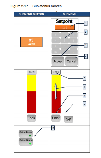
Table 2-11. Sub-Menus Descriptions
| Item | Description |
| 1 | Current Power setpoint value (in percentage) of maximum power (for example, 12%). |
| 2 | Enter the Power setpoint in percentage of the maximum power. |
| 3 | Accept new Power setpoint. |
| 4 | Return to the previous screen. |
| 5 | Power setpoint value in percentage of maximum power (for example, 57.5%). |
| 6 | Power Control Bar (disabled when locked). |
| 7 | Press Lock to unlock the Power Control Bar function (“Set” is displayed). |
| 8 | Press Set to change the power to the new setpoint and lock the Power Control Bar. |
| 9 | Press to turn on the Guide Beam. A Green dot lights up |

Table 2-12. Sub-Menus Descriptions
| Item | Description |
| 1 | Press the Emission Button and you are asked to confirm the emission startup process by pressing OK. Press Cancel to exit. |
| 2 | Press the IP address box to enter a new IP address. |
| 3 | Press the Net Mask box to enter a new net mask address. |
| 4 | Press the Web Access Code box to enter a new web access address. |
| 5 | Press Return to go back to the previous screen. |
| 6 | Opens the Pulse Settings menu (function described lower in table). |
| 7 | Enable or Disable the Gate mode |
| 8 | Enable or Disable the External Guide Laser control. |
| 9 | Enable or Disable the External Analog Power control. |
| 10 | Return to the previous screen. |
| 11 | Enable or Disable the Emission Control mode. |
| 12 | Enable or Disable the Modulation mode. |
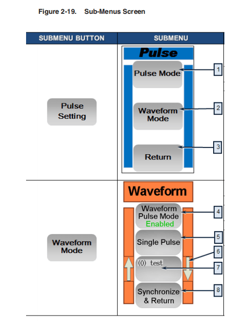
Table 2-13. Sub-Menus Descriptions
| Item | Description |
| 1 | Opens Pulse Mode sub-menu. |
| 2 | Opens Waveform Mode sub-menu. |
| 3 | Return to the previous screen. |
| 4 | Enables or Disables the Waveform Pulse Mode. |
| 5 | Single Pulse/Pulse Sequence. |
| 6 | Use the Up/Down Arrows to scroll to select a program from memory. |
| 7 | Selected the program in memory. |
| 8 | Transfers the selected program to the laser. |
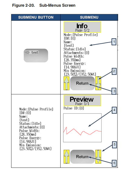
Table 2-14. Sub-Menus Descriptions
| Item | Description |
| 1 | Pulse Program Information Screen. Clicking anywhere in this area displays the Preview Screen. |
| 2 | Use the Up and Down arrows to scroll to select a program from memory. |
| 3 | Return to the previous screen. |
| 4 | Pulse Program Preview screen. |
| 5 | Use the Up and Down arrows to scroll to select a program from memory. |
| 6 | Return to the previous screen. |
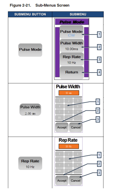
Table 2-15. Sub-Menus Descriptions
| Item | Description |
| 1 | Toggles between the Continuous (CW) and Pulsed (QCW) modes. |
| 2 | Opens Pulse Width dialog. |
| 3 | Opens Pulse Width dialog. |
| 4 | Return to the previous screen. |
| 5 | Enter Pulse Width in milliseconds (ms) range is 0.2 to 20 ms in .05 ms increments. |
| 6 | Accept the Pulse Width. |
| 7 | Cancel and return to the previous screen. |
| 8 | Enter Repetition Rate in Hertz (Hz) range is 1 to 5000 Hz in 1 Hz increments. |
| 9 | Accept the Repetition Rate. |
| 10 | Cancel and return to the previous screen. |
3 Computer Interface/Commands
RS-232 Configuration
A three-wire (RxD, TxD, GND) interface is used (null modem cable). The individual commands are described in “Interface Commands” on page 3-2. See “Interface Connector Pin Assignments” on page 2-19 for details on 24-pin interface connectivity.
The RS-232 interface is configured with the following parameters:
Table 3-1. RS-232 Parameters
| Parameter | Value |
| Baud Rate | 57,600 |
| Data Bits | 8 |
| Stop Bits | 1 |
| Parity | None |
| Flow Control | None |
Ethernet TCP/IP Interface
The IP address of the laser is shown on the front panel. Touching the screen where the address is shown displays the network setup menu where you can change the network settings.
The laser listens for connections on port 10001. The command must be sent as a single string in a single packet.
The individual commands are described in “Interface Commands” on page 3-2.
Table 3-2. Ethernet Interface Pinouts
| Pin | Description | Notes |
| 1 | TX+ | Transmit Data + |
| 2 | TX- | Transmit Data – |
| 3 | RX+ | Receive Data + |
| 4 | N/C | Not Connected |
| 5 | N/C | Not Connected |
| 6 | RX- | Receive Data – |
| 7 | N/C | Not Connected |
| 8 | N/C | Not Connected |
Interface Commands
All commands and responses consist of printable ASCII characters. Commands are typically three or four letter mnemonic codes followed by a parameter, if required.
All commands and responses are terminated with a <Carriage Return> (CR, 0x0D, r) character If a CR terminated string is received, but a valid command is not found, a response of “BCMD” is sent.
The commands are shown in Table 3-3, “Interface Commands” as all uppercase for clarity; the actual commands are not case sensitive.
A space character is also shown between the command and parameter for clarity. The space is not required.
Every command generates a response. The responses generally consist of the command echoed back. If there is a returned value, it is separated from the echoed command by a ‘:’ character.
Table 3-3. Interface Commands
| Code | Description | Example |
| ABN | Aiming Beam ON | Sent: “ANB” Response: “ABN” “ERR:Cannotenableguidebeam because external guide control is enabled.” |
| ABF | Aiming Beam OFF | Sent: “ABF” Response: “ABF” “ERR: Cannot disable guide beam because external guide control is enabled.” |
| DEABC | Disable External Aiming Beam Control —Disables hardware aiming beam control. | Sent: “DEABC” Response: “DEABC” |
| DEC | Disable External Control — Disables the analog current control input. Disables Dynamic Scaling in Waveform mode.a | Sent:”DEC”” Response: “DEC” or “ERR: Emission is ON!” |
| DGM | Disable Gate Mode — Disables internal pulse generator. | Sent: ”DGM” Response: “DGM” or “ERR: Emission is ON!” |
| DLE | Disable Hardware Emission Control — Disables hardware emission control. | Sent: “DLE”” Response: “DLE” or “ERR: Emission is ON!” |
| DMOD | Disable Modulation — Disables the modulation mode. | Sent: “DMOD”” Response: “DMOD” or “ERR: Emission is ON!” |
| DPMb | Disable PULSE Mode — Disables PULSE mode. | Sent: “DPM” Response: “DPM” or “ERR: Emission is ON!” |
| EEABC | Enable External Aiming Beam Control – Enables hardware aiming beam control. | Sent: “EEABC” Response: “EEABC” |
| EEC | Enable External Control — Enables the analog current control input. Enables Dynamic Scaling in Waveform mode.a | Sent: “EEC” Response: “EEC” or “ERR: Emission is ON!” |
| EGM | Enable Gate Mode — Enables internal pulse generator gated by signal applied to modulation input. | Sent: “EGM” Response: ”EGM” or “ERR: Emission is ON!” |
| ELE | Enable Hardware Emission Control — Enableshardware emission control. | Sent: “ELE” Response: “ELE” or “ERR: Emission is ON!” |
| EMOD | Enable Modulation – Enables the modulation mode. | Sent: “EMOD” Response: “EMOD” or “ERR: Emission is ON!” |
| EMOFF | Stop Emission – Stops emission. | Sent:: “EMOFF”” Response: “EMOFF” or “ERR: Emission is ON!” |
| EMON | Start Emission – Starts emission. | Sent: “EMON” Response: “EMON” |
| EPMb | Enable Pulse Mode — Enables Pulse mode. | Sent: “EPM” Response: “EPM” |
| ESTA | Read Extended Device Status — The extended status is reported as a number of bit-encoded 32-bit words. The response contains the information required by IPG for remote troubleshooting. | Sent: “ESTA” Response: “ESTA: 256;0;0;0;0;0;0;0;46;3” |
| LFPc | Lock Front Panel – Locks touch-screen display on the front panel of the laser. | Sent:: “LFP” Response: “LFP” or “ERR: Emission is ON!” |
| HELP | In case of no parameters returns the list of applicable commands. In case of a specified command name as a parameter returns the command description. | Sent: “HELP” Response: “Commands: STA ROP RPP RCT EMON EMOFF RET … RIP SIP RMASK SMASK RBAUD SBAUD HELP Done HELP <Command> for more information on a specific command” Sent: “HELP RPP” Response: “HELP: RPP – Read Peak Power” Sent: “HELP RCD” Response: “HELP: RCD – Command Not Listed” |
| RBAUD | Read Baud Rate — Reads the current RS-232 baud rate. The response is the command echoed back, followed by a delimiter of “: “ and then the communication speed index (see below). Index Speed (bits/s) 0 – 110 1 – 300 2 – 1200 3 – 2400 4 – 4800 5 – 9600 6 – 19200 7 – 38400 8 – 57600 default 9 – 115200 | Sent: “RBAUD” Response “RBAUD: 8” |
| RCE | Reset Critical Error — Followed by the code received from IPG clears critical errors. | Sent: “RCE 1123456123” Response: “RCE: Code Accepted” or “ERR: Code Incorrect” |
| RCS | Read Current Setpoint — Reads the setpoint for the LD current. The response is the command echoed back, followed by a delimiter of “: : and then the current setpoint in %. | Sent: “RCS” Response: “RCS: 56.7” (Indicates that the LD current setpoint is 56.7%) |
| RCT | Read Laser Temperature – Reads the internal temperature of the laser. The response is an echo of the command, a delimiter of “: “, and the temperature in degrees centigrade. | Sent: “RCT” Response: “RCT: 34.5” |
| REC | Read Error Counter — Reads critical error counter. | Sent: “REC” Response: “REC: 37” |
| RERR | Reset Errors — Resets any resettable errors. | Sent “RERR” Response: “RERR” |
| RET | Read Elapsed Time — Reads the elapsed time the laser has been ON. The time is returned in minutes. | Sent “RET” Response: “RET: 1105” |
| RFV | Read current software revision. | Sent: “RFV” Response: “RFV: 7.28;2.83;ND” |
| RMEC | Read Module Error Code. Returns error code stored in the laser or zero if normal operation. | Sent: “RMEC” Response: “RMEC: 0” |
| RNC | Read Minimum Current Setpoint — Reads the minimum current setpoint that can be set in the laser.The response is the command echoed back, followed by a delimiter of “: “ and then the minimum current as a percentage of the maximum. | Sent: “RNC” Response: “RNC: 10.0” (Indicates that the minimum setpoint is 10.0 %) |
| ROP | Read Output Power — Reads the output power in watts. The response is the command echoed back, a delimiter, and then either the power in watts “Off” if the emission is off, or “Low” if the power is below the reliable measurement threshold of the laser. | Sent: “ROP” Response: “ROP: 99.6” (Indicates that the output power is 99.6 watts) Sent: “ROP” Response: “ROP: Off” (Indicates that emission is off.) |
| RPP | Read Peak Power — Reads the output peak power in Watts. The response will be the command echoed back, a delimiter, and then either the power in watts “Off” if the emission is off, or “Low” if the power is below the reliable measurement threshold of the laser. | Sent: “RPP” Response: “RPP:730” (Indicates that the output peak power is 730 watts.) Sent: “RPP” Response: “RPP: Off” (Indicates that emission is off. |
| RPRR | Read Pulse Repetition Rate — Reads the pulse repetition rate of the internal pulse generator. The response is the command echoed back, followed by a delimiter of “:” and then the pulse width in Hz. | Sent: “RPRR” Response: “RPRR: 10.00” (Indicates that the PRR is 10 Hz.) |
| RPW | Read Pulse Width — Reads the pulse width of the internal pulse generator. The response is the command echoed back, followed by a delimiter of “:”and then the pulse width in ms. | Sent: “RPW” Response: “RPW: 5.550” (Indicates that the pulse width is 5.55 ms.) |
| RSN | Read Serial Number — Reads the serial number of the device. | Sent: “RSN” Response: “RSN: 6103081” |
| SBAUD | Set Baud Rate — Followed by an index (see below) sets RS-232 baud rate. The command sent via RS-232 has no response and the communication speed is changed just after receiving the command. The response to the command sent via Ethernet is the command echoed back, followed by a delimiter of “: “and then the communication speed index. Index Speed (bits/s) 0 – 110 1 – 300 2 – 1200 3 – 2400 4 – 4800 5 – 9600 6 – 19200 7 – 38400 8 – 57600 default 9 – 115200 | Sent: “SBAUD 9” Response (Ethernet only): “BAUD: 9” or “ERR: Invalid Baud Setting.Valid Settings = [] [0:110] [1:300] [2:1200] [3:2400] [4:4800] [5:9600] [6:19200] [7:38400] [8:57600] [9:115200] [END]” or “ERR: Emission is ON!” |
| SDC | Set Diode Current — Sets the diode current. The units are in percent of maximum current.The setpoint must be below 100% and above the minimum current setpoint. The current can also be set to 0. The response from the laser is the command echoed back, a delimiter of “:” and then the current setpoint for the laser. A value that is outside the acceptable range will receive a response of “ERR: Out of Range.” | Sent: “SDC 34.2” Response: “SDC: 34.2” (Current Setpoint is set to 34.2%.) Sent: “SDC 104.2” Response: “ERR: Argument out of range” (The setpoint is unchanged.) |
| SPRR | Set Pulse Repetition Rate — Sets the pulse repetition rate. The units are in Hz. The pulse width and the duty cycle (dependent on the pulse width and pulse repetition rate) must be within the specified range. The response from the laser is the command echoed back, a delimiter of “:” and then the pulse repetition rate. A value that is outside the acceptable range receives a response of “ERR: Duty cycle too high” or “ERR: Frequency out of range.” | Sent: “SPRR 10” Response: “SPRR: 10” (PRR is set to 10 Hz.) Sent: “SPRR 100” Response: “ERR: Duty cycle too high” (PRR is unchanged.) Sent: “SPRR 100000” Response: “ERR: Argument out of range” (PRR is unchanged.) |
| SPW | Set Pulse Width — Sets the pulse width. The units are in ms. The pulse width and the duty cycle (dependent on the pulse width and pulse repetition rate) must be within the specified range. The response from the laser is the command echoed back, a delimiter of “:” and then the pulse width. A value that is outside the acceptable range receives a response of “ERR: Out of range” or “ERR: Duty cycle too high.” | Sent: “SPW 5.5” Response: “SPW: 5.5” (Pulse Width is set to 5.5 ms.) Sent: “SPW 11000” Response: “ERR: Argument out of range.” (The pulse width is unchanged.) Sent: “SPW 8” Response: “ERR: Duty cycle too high.” (The pulse width is unchanged.) |
| STA | Read device status — The status is reported as a bit- encoded 32-bit word. Undefined bits or bits defined as“Reserved” can be in any state and should be ignored. Note: Each of the bits have a meaning as listed in Table 3-4 on page 3-9. | Sent: “STA” Response: “STA: 4100” This translates to the following: 4100 = 0x1004, so bits 2 and 12 are set.This means that emission is on and modulation is enabled. |
| SIP | Set IP — Followed by a number in dot-decimal notation sets the IP address for the laser. | Sent: “SIP 10.0.0.2” Response: “SIP: 10.0.0.2” |
| SQSEL | Select Sequence — Selects Pulse Sequence Mode and Pulse Sequence ID. If the command is not followed by the ID number or the ID is invalid, then the existing (or last) selection is used. Note: It is not possible to switch to sequence mode if Waveform mode is enabled and no sequences exist. An error is returned if that is the case. If the Key Switch is in the Remote position, a waveform configuration is automatically executed before a response is returned. | Sent: “SQSEL 5” Response: “New setting applied. Waveform Mode: Pulse Sequence Selected Sequence: ID[5] – Name[Test1]” |
| UFP | Unlock Front Panel — Unlocks touch-screen display on the front panel of the laser. | Sent: “UFP” Response: “UFP” or “BCMD” in case of key is in REMOTE position” or “Emission is ON!” |
- Laserswith Pulse Shaping option only.
- QCWModels only.
- Laserwith Touch-Screen Display only.
Table 3-4. Bit Meanings
| Bit 0 | – | 0 | = | Normal Operation |
| – | 1 | = | Command Buffer Overload | |
| Bit 1 | – | 0 | = | Normal Operation |
| – | 1 | = | Overheat | |
| Bit 2 | – | 0 | = | Emission Off |
| – | 1 | = | Emission On | |
| Bit 3 | – | 0 | = | Back Reflection OK |
| – | 1 | = | High Back Reflection Level | |
| Bit 4 | – | 0 | = | Analog Power Control Disabled |
| – | 1 | = | Analog Power Control Enabled | |
| Bit 5 | – | 0 | = | Normal Operation |
| – | 1 | = | Pulse Too Long | |
| Bit 6 | – | Reserved | ||
| Bit 7 | – | Reserved | ||
| Bit 8 | – | 0 | = | Aiming Beam OFF |
| – | 1 | = | Aiming Beam ON | |
| Bit 9 | – | 0 | = | Normal Operation |
| – | 1 | = | Pulse too Short | |
| Bit 10 | – | 0 | = | CW Mode |
| – | 1 | = | Pulsed Mode | |
| Bit 11 | – | 0 | = | Power Supply ON |
| – | 1 | = | Power Supply OFF | |
| Bit 12 | – | 0 | = | Modulation Disabled |
| – | 1 | = | Modulation Enabled | |
| Bit 13 | – | Reserved | ||
| Bit 14 | – | Reserved | ||
| Bit 15 | – | 0 | = | Emission is out of the 3 second start-up state. |
| – | 1 | = | Emission is in the 3 second start-up state. | |
| Bit 16 | – | 0 | = | Gate Mode Disabled |
| – | 1 | = | Gate Mode Enabled | |
| Bit 17 | – | 0 | = | Normal Operation |
| – | 1 | = | High Pulse Energy | |
| Bit 18 | – | 0 | = | Hardware Emission Control Disabled |
| – | 1 | = | Hardware Emission Control Enabled | |
| Bit 19 | – | 0 | = | Normal Operation |
| – | 1 | = | Power Supply Failure | |
| Bit 20 | – | 0 | = | Front Panel Display is Unlocked |
| – | 1 | = | Front Panel Display is Locked | |
| Bit 21 | – | 0 | = | Keyswitch is in ON position |
| – | 1 | = | Keyswitch is in REM position | |
| Bit 22 | – | 0 | = | Waveform Pulse Mode OFF |
| – | 1 | = | Waveform Pulse Mode ON | |
| Bit 23 | – | 0 | = | Normal Operation |
| – | 1 | = | Duty Cycle Too High | |
| Bit 24 | – | 0 | = | Normal Operation |
| – | 1 | = | Low Temperature | |
| Bit 25 | – | 0 | = | Normal Operation |
| – | 1 | = | Power Supply Alarm | |
| Bit 26 | – | Reserved | ||
| Bit 27 | – | 1 | = | Hardware Aiming Beam Control Disabled |
| – | 0 | = | Hardware Aiming Beam Control Enabled | |
| Bit 28 | – | Reserved | ||
| Bit 29 | – | 0 | = | Normal Operation |
| 1 | = | Critical Error | ||
| Bit 30 | 0 | = | Fiber Interlock OK | |
| 1 | = | Fiber Interlock Active | ||
| Bit 31 | 0 | = | Normal Operation | |
| 1 | = | High Average Power | ||
- QCWModels only.
- Laserswith Touch-Screen Display only.
- Laserswith Pulse Shaping Option only.
Table 3-5. TCP-IP Configuration Commands
| Code | Description | Example |
| DDHCP | Disable DHCP – Disables DHCP client | Sent: “DDHCP” Response: “DDHCP” or “ERR: Emission is ON!” |
| EDHCP | Enable DHCP – Enables DHCP client. | Sent: “EDHCP” Response: “EDHCP” or “ERR: Emission is ON!” |
| RDGW | Read Default Gateway — Reads the current default gateway of the device. The response is the command echoed back, followed by a delimiter of “: “ and then the default gateway in dot-decimal notation. | Sent: “RDGW” Response: “RDGW: 192.168.1.1” |
| RDHCP | Read DHCP — Reads the current status of DHCP client function. The response is the command echoed back, followed by a delimiter of “: “and then either “ON” or “OFF.” | Sent: “RDHCP” Response: “RDHCP: OFF” |
| RIP | Read IP —Reads the current IP address of the device. The response is the command echoed back, followed by a delimiter of “:” and then the IP address in dot-decimal notation. | Sent: “RIP” Response: “RIP: 192.168.1.230” |
| RLHN | Read Local Host Name — Reads the current local host name of the device. The response is the command echoed back, followed by a delimiter of “:” and then the name. | Sent: “RLHN” Response: “RLHN: IPG- 12004020” |
| RMAC | Read MAC Address — Reads the current MAC address of the laser.The response is the command echoed back, followed by a delimiter of “:” and then the MAC address in a form of six groups of two hexadecimal digits, separated by hyphens (-). | Sent: “RMAC” Response: “RMAC: A1-B2-C3- D4-E5-F6” |
| RMASK | Read Subnet Mask — Reads the current subnet mask of the device. The response is the command echoed back, followed by a delimiter of “:” and then the subnet mask in dot-decimal notation. | Sent: “RMASK” Response: “RMASK: 255.255.240.0” |
| RSTIP | ResetTCP/IP Settings – Resets the settings to the default ones: DHCP client OFF IP Address: 192.168.3.230 Default Gateway: 192.168.0.1 Subnet Mask: 255.255.240.0 Local Host Name: IPG-”serial number” | Sent: “RSTIP” Response: “RSTIP” or “ERR: Emission is ON!” |
| SDGW | Set Default Gateway — Followed by a number in dot- decimal notation sets the default gateway for the laser. | Sent: “SDGW 192.168.0.1” Response:“SDGW:192.168.0.1” or “ERR: Emission is ON!” |
| SIP | Set IP — Followed by a number in dot-decimal notation sets the IP address for the laser. | Sent: “SIP 192.168.1.231” Response: “SIP: 192.168.1.231” or “ERR: Emission is ON!” |
| SMAC | Set MAC Address — Followed by six groups of two hexadecimal digits, separated by hyphens (-), sets the MAC address for the laser. | Sent: “SMAC 12-34-56-78-EF- EF” Response: “SMAC: 12-34-56-78- EF-EF” or “ERR: Emission is ON!” |
| SMASK | Set Subnet Mask – Followed by a number in dot-decimal notation sets the subnet mask for the laser. | Sent: “SMASK 255.255.0.0” Response: “SMASK: 255.255.0.0″ or “ERR: Emission is ON!” |
| SLHN | Set Local Host Name — Specifies the name of the device within the network. | Sent: “SLHN IPG-12004020” Response: “SLHN: IPG- 12004020” or “ERR: Emission is ON!” |
| DWPM | Disable Waveform Pulse Mode — Disables internal arbitrary waveform generator (pulse shaping). | Sent: “DWPM” Response: “DWPM” or “ERR: Emission is ON!” |
| EWPM | Enable Waveform Pulse Mode -— Enables internal arbitrary waveform generator (Pulse Shaping). | Sent: “EWPM” Response: “EWPM” or “ERR: No pulses available, cannot enable waveform mode.” or “ERR: No sequences available, cannot enable waveform mode.” or “ERR: Emission is ON!” or “ERR: Laser is not in Pulse Mode!” |
| PCFG | Configure Waveform Mode — Returns the status of the Waveform Mode and the ID number of the selected Pulse Profile or Pulse Sequence. | Sent: “PCFG” Response: “PCFG: [] [Status:Disabled] [Mode:Profile] [ID:2] [END]” |
| PRLS | Profile List — Displays a list of available Pulse Profiles stored in the device library. | Sent: “PRLS” Response: “PRLS: [] [0:New Shape 0] [2:New Shape 2] [END]” |
| PRSEL | Select Profile — Selects Single Pulse Mode and Pulse Profile ID. If the command is not followed by the ID number or the ID is invalid, then the existing selection is used. | Sent: “PRSEL 2” Response: “PRSEL: [2:New Shape 2]” or “ERR: Entered pulse ID is not valid” or “ERR: No pulses are available” |
| SQLS | Sequence List — Displays a list of available Pulse Sequence programs stored in the device library. | Sent: “SQLS” Response: “SQLS: [] [0:New Program 0] [4:New Program 4] [END]” |
| SQSEL | Select Sequence – Selects Pulse Sequence Mode and Pulse Sequence ID. If the command is not followed by the ID number or the ID is invalid, then the existing (or last) selection is used. | Sent: “SQSEL 4” Response: “SQSEL: [4:New Program 4]” or “ERR: Entered sequence ID is not valid” or “ERR: No sequences are available” |
The following commands in Table 3-6 are for lasers with the Pulse Shaping option only.
Table 3-6. Waveform Mode (Pulse Shaping) Specific Commands
| Code | Description | Example |
| DWPM | Disable Waveform Pulse Mode — Disables internal arbitrary waveform generator (pulse shaping). | Sent: “DWPM” Response: “DWPM” or “ERR: Emission is ON!” |
| EWPM | Enable Waveform Pulse Mode -— Enables internal arbitrary waveform generator (Pulse Shaping). | Sent: “EWPM” Response: “EWPM” or “ERR: No pulses available, cannot enable waveform mode.” or “ERR: No sequences available, cannot enable waveform mode.” or “ERR: Emission is ON!” or “ERR: Laser is not in Pulse Mode!” |
| PCFG | Configure Waveform Mode — Returns the status of the Waveform Mode and the ID number of the selected Pulse Profile or Pulse Sequence. | Sent: “PCFG” Response: “PCFG: [] [Status:Disabled] [Mode:Profile] [ID:2] [END]” |
| PRLS | Profile List — Displays a list of available Pulse Profiles stored in the device library. | Sent: “PRLS” Response: “PRLS: [] [0:New Shape 0] [2:New Shape 2] [END]” |
| PRSEL | Select Profile — Selects Single Pulse Mode and Pulse Profile ID. If the command is not followed by the ID number or the ID is invalid, then the existing selection is used. | Sent: “PRSEL 2” Response: “PRSEL: [2:New Shape 2]” or “ERR: Entered pulse ID is not valid” or “ERR: No pulses are available” |
| SQLS | Sequence List — Displays a list of available Pulse Sequence programs stored in the device library. | Sent: “SQLS” Response: “SQLS: [] [0:New Program 0] [4:New Program 4] [END]” |
| SQSEL | Select Sequence – Selects Pulse Sequence Mode and Pulse Sequence ID. If the command is not followed by the ID number or the ID is invalid, then the existing (or last) selection is used. | Sent: “SQSEL 4” Response: “SQSEL: [4:New Program 4]” or “ERR: Entered sequence ID is not valid” or “ERR: No sequences are available” |
4 Pulse Shaping
Overview
The Pulse Shaper program lets you sketch pulse points. It automatically fills in pulse (power level) lines, and computes all the emission pulse characteristics simultaneously. It also performs auto-correction in case constraints are violated.
A laser emission pulse is a custom time-based emission power signal, constrained by an output sample time, maximum power, maximum energy and minimum current (power) threshold, all of which are pre-configured in the laser.
Pulses are not zeroed visually when they go under the power threshold, although that is not reflected in the pulse energy calculation.
To avoid pulse energy limits, either shorten your pulse widths or reduce the value of the Time Scale.
Each time you change a Pulse Shape profile, the pulse widths are updated to reflect the current sketched pulse. You cannot exceed the limits established in the laser configuration.
You can create effective Pulse Shapes to meet the changing requirements of your applications. You can store Pulse Shapes in a Pulse Profiles library on the laser or locally to your computer. You can also create and store Pulse Sequences (combinations of pulse profiles, delays, and repeats) in a Pulse Sequences library or locally to your computer.
Figure 4-1 shows the Pulse Shaper interface.
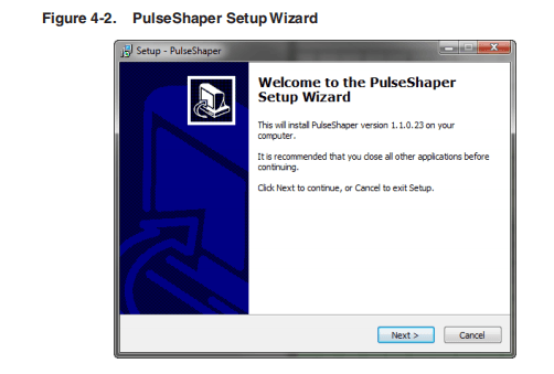
- Click Next to continue.
- Select a destination location or accept the default location for the installation as shown in Figure 4-3 and click Next.
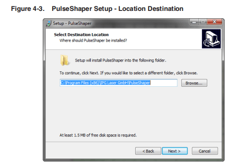
- ClickNext to accept the default Start Menu folder for the Pulse Shaper shortcut.
- Click Browse if you want to change the default Start menu to another location.
- Click the Don’t create a Start Menu folder checkbox to skip this step.
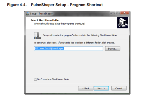
- Click Next to create a PulseShaper icon on your desktop (default) as shown in Figure 4-5.
- Deselect the Create a desktop icon checkbox if you want to skip this step.

- Click Install to continue with installation as shown in Figure 4-6.
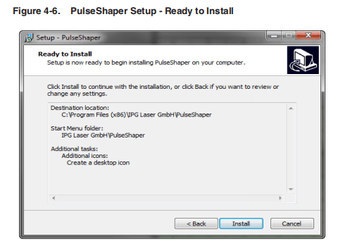
- Click Finish to exit Setup as shown in Figure 4-7. By default, the Pulse Shaper program launches when you exit Setup.
- Deselect the Launch Pulse Shaper checkbox if you do not want Pulse Shaper to launch upon exiting Setup.
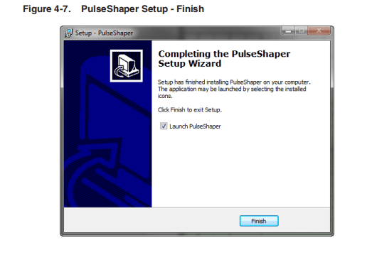
Configuring a Local Area Connection for Ethernet
To configure a local area connection for Ethernet:
- Goto Control Panel -> Network and Internet -> Network and Sharing Center.
- Click Change adapter settings.
- Selecta Local Area Connection icon. The following window appears as shown in Figure 4-8.

- Click Properties.The following window appears as shown in Figure 4-9.
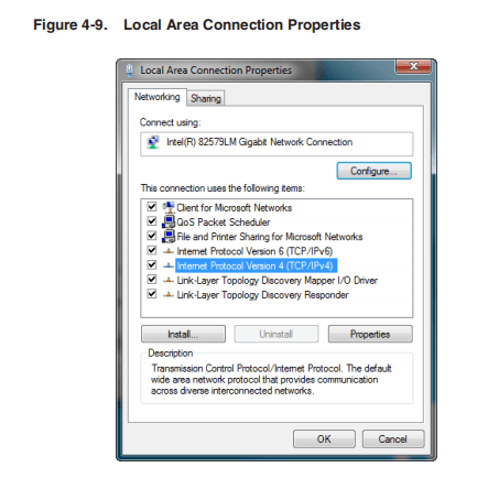
- Select Internet Protocol Version 4 (TCP/IPv4).
- Clickthe Properties button. The following window appears as shown in Figure 4-10.
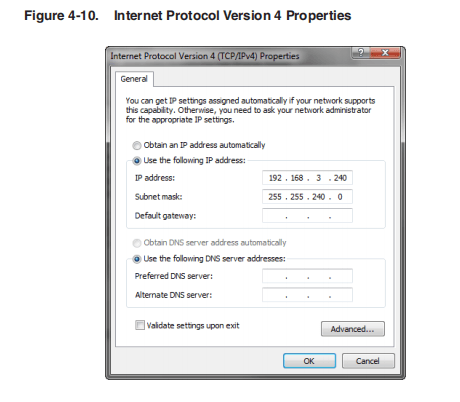
- Click the Use the following IP address radio button to manually assign the IP address.
- Assign the IP address to 192.68.3.23x (x cannot be 0).
- Assign the subnet mask setting to 255.255.240.0.
- Click OKto accept these manual changes.
Pulse Shaper Configuration Procedures
You can connect to the Pulse Shaper program from either an Ethernet or RS-232 connection.
Connecting using Ethernet
You can connect to the Pulse Shaper using an Ethernet connection from your computer to the laser.
This procedure starts a connection to the laser over a network via a specific IP Serial Port.
To connect using Ethernet:
- Connect your PC to the laser using network cable.
- Configure the Local Area Connection settings for Ethernet as explained in “Configuring a Local Area Connection for Ethernet” on page 4-9.
- Start the Pulse Shaper program.
- ClickLaser->Connect. The Laser Connection dialog box appears as shown in Figure 4-11.
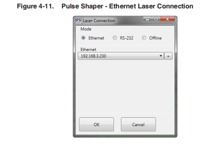
- Click the Ethernet radio button.
- Select the IP address of the laser from the drop-down listbox.
- Click OK.
The status is displayed in the Session box indicating that the connection is successful.

Connecting Using RS-232
You can connect to the Pulse Shaper program using an RS-232 Serial connection from your computer to the laser.
This procedure starts a connection to the laser overRS-232 serial cable via a specific port on the host machine.
To configure an RS-232 serial connection:
- Connect a RS-232 serial cable from your computer to the laser.
- Start the Pulse Shaper program.
- Click Laser->Connect. The Laser Connection dialog box appears as shown in Figure 4-12.

- Click the RS-232 radio button.
- Select avalid COM port on the laser from the drop-down listbox.
- Click OK.
The status is displayed in the Session box indicating that the connection is successful.

Using the Offline Option
You can export and import a configuration from a laser connection and store it forlater use with the Offline option. When you export a configuration, the chart(including unused time segments) is preserved with the original time scale.
To use the Offline option:
- Start the Pulse Shaper program.
- ClickLaser->Connect. The Laser Connection dialog box appears as shown in Figure 4-13.
- Click Offline.
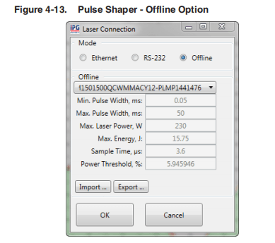
- Export or import apulse configuration as detailed in the next sections.
Exporting a Configuration
To export a saved configuration from a previous laser connection (lcfg file.):
- Click Export…The following dialog box appears as shown in Figure 4-14 on page 4-15.

- Accept the default filename or rename the file and click Save.
Importing a Configuration
To import a saved configuration from a previous laser connection (lcfg file.):
- Click Import…The following dialog box appears as shown in Figure 4-15 on page 4-16.
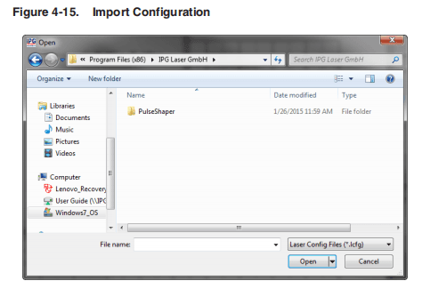
- Select the configuration file (.lcfg) and click Open.
- Click Yes to overwrite an existing configuration if applicable.
Using the Pulse Shaper Program
To start the Pulse Shaper program:
- Go to All Programs ->IPG Laser GmbH ->Pulse Shaper.
- Select Pulse Shaper.

Table 4-1 provides the descriptions for the four menu items in the Pulse Shaper program.
Table 4-1. Pulse Shaper Menu Items
| Menu Name | Description |
| Laser | • Connect — Connects to the laser via Ethernet or RS-232. You can also the Offline option and import a saved Pulse Profile configuration file. • Disconnect — Disconnects the Pulse Shaper program from the laser. • Synchronization — Synchronizes the Pulse Shapes with the laser using the Ethernet IP address or RS-232 connection. • Backup — Backs up the configuration profile to a .bkp file. • Restore — Restores the configuration profile from a backup file. All current data is replaced with data stored in the backup file. • Pulse mode — Indicates that Pulse mode is active. • Exit — Closes the Pulse Shaper program. |
| Shape | • New — Creates a new Pulse Shaping profile. • Read from Laser — Loads and displays a Pulse Shaping profile from the laser. • Write to Laser — Saves the current Pulse Shaping profile to the laser. This option only saves the effective pulse. • Delete in Laser — Deletes a Pulse Shaping profile that is stored in the laser. • Read from File — Loads and displays a Pulse Shaping profile from a saved file (.shp) on your computer. • Write to File — Saves the current Pulse Shaping profile to a file (.shp) to your computer. |
| Sequence | • New — Creates a new Pulse Sequence. • Read from Laser — Loads and display a Pulse Sequence from the laser. • Write to Laser — Saves a Pulse Sequence to the laser. • Delete in Laser — Deletes a Pulse Sequence from the laser. • Read from File — Loads and displays a Pulse Sequence from a saved file (.sec) on your computer. • Write to File — Saves a Pulse Sequence to a file (.sec) to your computer. |
| Scale | • New — Creates a new Pulse Scale. • Read from Laser — Loads and display a Pulse Scale from the laser. • Write to Laser — Saves current Pulse Scale to the laser.This option only saves the effective Pulse Scale. • Delete in Laser — Deletes a Pulse Scale that stored in the laser. • Read from File — Loads and display a Pulse Scale from a file (.scl) on your computer. • Write to File — Saves current Pulse Scale to a file (.scl) to your computer. |
Table 4-2 provides descriptions for the Pulse Shaper main window options.
Table 4-2. Main Window Descriptions
| Name | Description |
| Session Panel | |
| Mode | Displays the active session type. |
| Connection | Displays the connection status (Ethernet or RS-232). |
| Laser Configuration Panel | |
| ID | The configuration identification for the laser. |
| SN | The serial number of the laser. |
| CW | Indicates if the CW operating mode (Continuous Wave) is active. In CW mode, the maximum pulse duration and duty cycle are not applicable. |
| Max Width, ms | Maximum allowed pulse width. |
| Min Width, ms | Minimum allowed pulse width. |
| Max Power, W | Maximum allowed pulse power. |
| Max Energy, J | Maximum allowed pulse energy. |
| Sample Time, µs | Minimum interval for pulse points. |
| Power Threshold % | Emission (current) effective zero level. |
Laser Control Tab
The Laser Control tab lets you activate a Pulse Sequence.
Figure 4-18 shows the Laser Control tab.
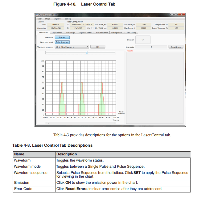
Shape Editor Tab
The Shape Editor lets you create and edit various Pulse Shape profiles and save them in the Pulse Shapes library on the laser or locally to your computer.
Figure 4-19 shows the Shape Editor tab.
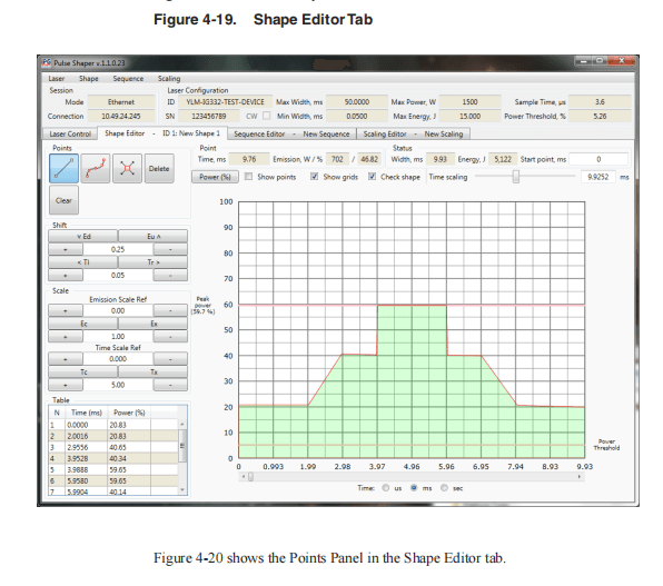
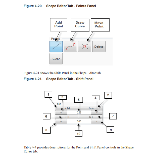
Table 4-4. Shape Editor Tab – Points and Shift Panel Controls
| Item | Name | Description |
| Points | ||
| Add Point Tool | Plots pulse points in the chart and automatically forms lines. | |
| Draw Curve Tool | Plots an arbitrary pulse in the chart and automatically forms points and lines along the graph (using your mouse). | |
| Move Point Tool | Relocates a pulse point on the chart. | |
| Delete Point | Deletes a pulse point from the Table box. | |
| Clear | Clears the entire pulse chart. | |
| Shift Panela | ||
| 1 | Emission Shift Down | Shifts all pulse points down in emission. |
| 2 | Emission Shift Up | Shifts all pulse points up in emission. |
| 3 | Increase Emission Shift Step | Increases the emission shifting step size. |
| 4 | Decrease Emission Shift Step | Decreases the emission shifting step size. |
| 5 | Emission Step | Sets the emission shifting step size (.25 – 100%). |
| 6 | Time Shift Left | Shift all pulse points back in time. |
| 7 | Time Shift Right | Shifts all pulse points forward in time. |
| 8 | Increase Time Shift Step | Increases the time shifting step size. |
| 9 | Decrease Time Shift Step | Decreases the time shifting step size. |
| 10 | Emission Scale Ref | Sets the reference point for emission scaling (0 – 100%). |
- Due to the digitized nature of the pulses, approximations are used to compute modulations. Modulation step values (especially very small ones) might not have an effect. IPG recommends you save the original pulse while manipulating the pulse for easy comparison between the modulated pulse and the original.

Table 4-5. Shape Editor Tab – Scale Panel Controls
| Name | Description | |
| Emission Scale Refa | ||
| 1 | Increase Emission Scale Ref | Increases the reference point for emission scaling. |
| 2 | Decrease Emission Scale Ref | Decreases the reference point for emission scaling. |
| 3 | Time Step | Sets the time shifting step size (ms). |
| 4 | Compress Emission | Compresses all pulse points in emission with regards to the reference point. |
| 5 | Expand Emission | Expands all pulse points in emission with regards to the reference point. |
| 6 | Decrease Emission Scale Step | Decreases the step size for emission scaling. |
| 7 | Increase Emission Scale Step | Increases the step size for emission scaling. |
| 8 | Emission Scale Step | Sets the step size for emission scaling (.25 – 100%). |
| Time Scale Ref | ||
| 9 | IncreaseTimeScale Ref | Increases the reference point for time scaling. |
| 10 | Decrease Time Scale Step | Decreases the step size for time scaling. |
| 11 | Time Scale Ref | Sets the reference point for time scaling (0 – 50ms). |
| 12 | Compress Time | Compresses all pulse points in time with regards to the reference point. |
| 13 | Expand Time | Expands all pulse points in time with regards to the reference point. |
| 14 | IncreaseTimeScale Step | Increases the step size for time scaling. |
| 15 | Decrease Time Scale Ref: | Decreases the reference point for time scaling. |
| 16 | Mod Time Scale | Sets the step size for time scaling (.25 – 100%). |
- Due to the digitized nature of the pulses, approximations are used to compute modulations, so modulation step values, especially the very small ones might not have an effect. It is recommended to save original pulse while manipulating the pulse so it’s easy to compare the modulated pulse against the original.
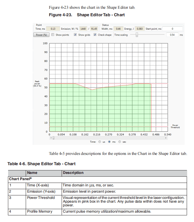
- Due to the digitized nature of the pulses, approximations are used to compute modulations, so modulation step values, especially the very small ones might not have an effect. It is recommended to save original pulse while manipulating the pulse so it is easy to compare the modulated pulse against the original.
Creating a New Pulse Shape Profile
To create a new Pulse Shape profile:
- Select Shape-> New.
- Select atime scale unit (ms, ms, or sec) from one of the Time: buttons at the bottom of the window.
- Draw the shape by adding points.
- To change points, modify values in the Table box in the left pane.
- Once the Pulse Shape is complete, you can save it to the Pulse Shapes libraryor locally on your computer.
- To save to the Pulse Shapes library, on the laser select Shape -> Write to Laser.
- To save to your computer, select Shape -> Write to File.
Shifting a Pulse Shape
You can manipulate an existing Pulse Shape to create new variations. This method can save you time and achieve better symmetry. See Figure 4-21 for an illustration of Shift Panel controls.
To shift a pulse:
- Select Newfrom the Shape menu.
- Create apreliminary pulse (preferably an alternating one) such as a square or sine wave.
- Set an emission step percentage value in the Shift Panel.
- In the Shift Panel, click Emission Shift Down (Eu∧) or Emission Shift Up (∨ Ed) to introduce an emission offset to the pulse.
- Set acertain Time Step value in the Shift Panel.
- ClickTime Shift Left (Tr>) Time Shift Right (<TI) to introduce a time offset to the pulse.
- Setan Emission Scale Ref percentage value. It should be the effective zero point of your pulse to get the best result.
For example, if you are modulating a sine wave, set to be in the center point.Also, set an Emission Scale percentage value then click Expand Emission or Compress Emission to scale effective emission with respect to the reference point.
- Use the Time scaling slider to set a Time scale value. It should be the effective zero point of your pulse to get the best result.
Because of the sample time constraint, scaling can be unsymmetrical, and there could be a small range of ineffective scaling factors, all that is due to sample approximation during the calculations.
IPG recommends you save the original pulse prior to modulating a pulse.
Pulse Shape Storage and Recall
On a Laser
This section requires connection to the laser. It is important to write pulses to the laser to use and activate them.
- Sketcha Pulse shape as explained in “Creating a Single Pulse Shape” on page 4-28.
- Select Shape->Writeto Laser.
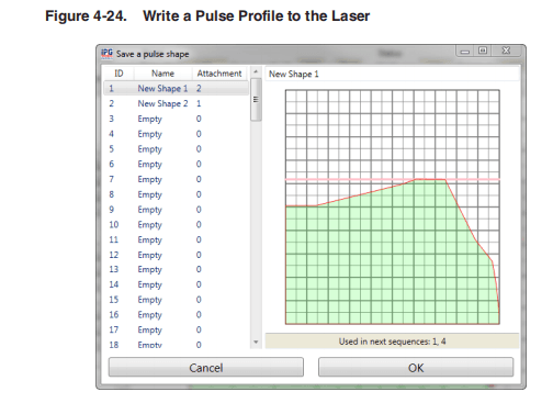
- Select apulse ID or enter a new name for the pulse profile and click OK.
The message “Shape was saved” appears.
The pulse data is encoded and transmitted to the laser for storage.
To recall:
- Select Shape->Readfrom Laser.
- Select a pulse profile ID and click OK.
The Pulse Shape is fetched, decoded, and displayed on the chart. The displayed pulse might appear differently as any unused time in the chart is removed as only the effective pulse width is saved.
On a Host PC
You can write Pulse Sequences to your computer to use and activate them in the Sequence Editor.
To save a Pulse Sequence your computer:
- Select Shape-> Write to File.
- Enter aname for the file and click Save.
To recall a Pulse Shape:
- Select Shape->Readfrom File.
- Select apulse ID and click OK.
The Pulse Shape is fetched and loaded into the chart.
Deleting a Pulse Profile
You can only delete or make changes to a pulse if the pulse profile status is “Idle”. The “In Use” status identifies that the laser is configured with that pulse.
You cannot delete a pulse profile that has an attachment status greater than zero, which means that the pulse is used by one or more existing sequences.
However, you can overwrite a pulse if you accept to bypass the warning.
To delete a Pulse Shape profile:
- Select Shape->Delete in Laser. The Delete a Pulse Shape dialog box appears.

- Select a profile ID to delete.
- Click Delete.
- Click Yes in the confirmation box.
Single Pulse Activation
To activate a Single Pulse:
- SelectLaser-> Connect. See “Pulse Shaper Configuration Procedures” on page 4-12 for the steps for connecting via Ethernet or RS-232.
- Click the Laser Control tab.
- Toggle the Waveform button to Enabled.
- Toggle the Waveform mode to Single Pulse.
- Select a Wave form shape from the listbox.
- Click SET.
- Click Emissionto confirm and start countdown.
The selected pulse is emitted after the countdown.
- Click Emission again to clear the status. This also stops a pulse sequence if it is set to infinite repeats.

Single Pulse Activation using the Touch-Display Screen
This section requires connection to the laser.
- After storing a pulse to the laser, ensure the Emergency Stop button is released on the laser and then press the green button to turn on the power supply.

Both Analog and Modulation modes must be set to “Off” to configure the pulse mode.
You can access these modes from the Setup submenu in the Touch-Screen Display.
- On the laser touch-screen, select Setup->PulseSetting-> Waveform Mode.
- Toggle Waveform Pulse Mode to Enabled.
- Select SinglePulse.
- Use the Up/Down arrows to select aspecific pulse.
If no pulse profile is saved the laser’s pulse profile list, then “!! No Profiles Available!!” is displayed.
- PulseInformation/Preview (optional) —To view information about the pulse, click on the Pulse Browser button. This is the button with the name of the pulse. Once the information page appears, you can use the arrows to scroll through all available pages.
- Click anywhere in the text space to go to the Preview page.You can see the shape of the pulse.
- Click Return twice to go back to the Waveform page.
- Click Configure& Return.
It is important to configure the laser with the selected pulse (once) before usage.
- After the configuration is complete, click Return twice to go back to the main page.
- Click Emission and then click OK to confirm and start countdown.The selected pulse is emitted after the countdown.
- Click Emission again to clear the status.
Scaling Editor
The Scaling Editor lets you scale pulses within a sequence (ramp up and down).
If Analog Power Control is enabled, it allows on-the-fly scaling of the Pulse Sequence by varying analog input signal. You do not need to use Scaling Editor.
See “Accessing theWeb User Utility” on page A-5 to enableAnalog Power Control.
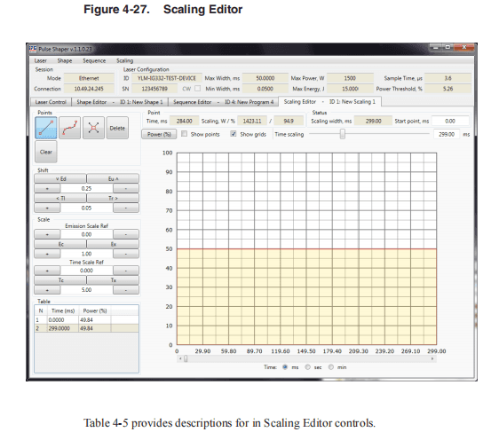
Table 4-7. Scale Editor Controls
| Name | Description | |
| Point Panel | ||
| 1 | Time, ms, sec, or min | Time scale unit in ms, sec, or min. |
| 2 | Scaling, W % | Enter a start point value for viewing the Pulse Scale in the chart. |
| 3 | Power (%) | Click the Power button to toggle between percentage and watts. |
| 4 | Show points | Click the Show points checkbox to display graphical points along the grid lines in the Scale chart. This option is disabled by default. |
| 5 | Show grid | Click Show grids to display a grid of horizontal and vertical lines for aligning pulse points in the Scale chart.This option is enabled by default. |
| 6 | Time scaling | Use the Time scaling slider to adjust the zoom in and out. Use the time shift controls and alignment cursors for more accurate editing. Use the Time and Emission indicators in the Status panel for guidance. |
| Status Panel | ||
| 3 | Scaling width, ms, sec, or min | Total time between start and finish. |
| 4 | Start point, ms, sec, or min. | Start value from a certain point. |
Creating a New Pulse Scale
.To create a Pulse Scale:
- Select Scale-> New.
- Select a scaling width.
- Draw the scale by adding points.
- Tosave to the Pulse Sequence library, on the laser select Scale -> Write to Laser.
- To save to your computer, select Scale -> Write to File.
Sequence Editor
A Pulse Sequence is an arrangement of pulses, designed for finite or infinite repeats,and organized into steps. Each step has an assigned an existing pulse, pre-delay, andrepeat amount.
The Pulse Shaping program checks each created sequence for average power and other laser limitation violation, and prompts you to make adjustments.
The Sequence Editor lets you create a sequence of pulses (pulse train) using Pulse Shapes from Pulse Sequence library.
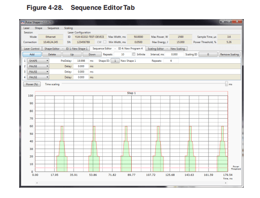
Table 4-8 provides descriptions for in Sequence Editor controls.
Table 4-8. Sequence Editor Controls
| Name | Description |
| Add | Click Add to insert a sequence step prior to the one currently selected. |
| Delete | Click Delete to remove the selected sequence step. |
| Up | Click Up to move the selected sequence up in the order of sequence steps. |
| Down | Click Down to move the selected sequence step down in the order of sequence steps. |
| Repeats | The number of repeats for the current sequence. |
| Infinite | Check the Infinite checkbox for continuous repeats of the current sequence. |
| Interval. ms | Enter a interval value. |
| Scaling ID | Click to open the Pulse Scaling dialog box where you can select a scaling ID. |
| Remove Scaling | Click Remove Scaling to remove the select scaling ID from the Scaling ID box. |
| Name | Names of the current sequence. |
| Pre-Delay | A delay that precedes every repetition of the corresponding sequence step. |
| Repeats | The number of times to repeat the corresponding. |
Creating a New Pulse Sequence
You can make a pulse train with variable Pulse Shapes and pulse repetition rates.
To create a Pulse Sequence:
- SelectLaser-> Connect. See “Pulse Shaper Configuration Procedures” on page 4-12 for the steps for connecting via Ethernet or RS-232.
- Select Sequence-> New.
- Select the required Pulse Shape from Pulse Shapes library.
- Define the delays between pulses in the Delaybox.
- Enter the number of repeats in the Repeatsbox.
- Select scaling of pulses (ramp up/ramp down) from the Pulse library and addthem on top of the sequence.
If Analog Power Control is enabled, it allows on-the-fly scaling of the Pulse Sequenceby varying analog input signal.
You do not need to use Scaling Editor. See “Accessing the Web User Utility” on page A-5 to enableAnalog Power Control.
- To save to the Pulse Sequence library, on the laser select Sequence ->Write to Laser.
- To save to your computer, select Sequence -> Write to File.
Building a Sequence
To build a sequence:
- Select New from the Sequence menu. A new Pulse Sequence appears in the Sequence Editor tab.
- Click Add to add a sequence step.
- Enter avalue (in ms) in the Delay box.
- Select a Pulse Profile from the listbox.

- Enter a number of repeats (number of times the selected Pulse Profile with delay must be repeated ) in the Repeats box.
- Click Add again to add more sequence steps.
You can set the number of sequence repeats by setting values in the Repeats box and Interval, ms box.
- Click the Shape ID button to display a list of Pulse Shapes as shown in Figure 4-29.

- Select a shape ID for the sequence and click OK.
- Click the Scaling ID button to display alist of Pulse Scaling IDs as shown in Figure 4-30.

- Select a scaling ID for the sequence and click OK.
The preview of the sequence is refreshed when changes are made to the pulse.Additionally, laser limitation violations are re-checked.
Modifying a Pulse Sequence
To modify a sequence:
- Highlight an existing step.
- Click Up to shift up the selected sequence step in the sequence order.
- Click Down to shift down the selected sequence step in the sequence order.
- Click Delete to remove the selected sequence step.
Pulse Sequence Storage and Recall
This section requires connection to the laser.
On a Laser
You can write Pulse Sequences to the laser to use and activate them in the Sequence Editor.
- Select Sequence->Writeto Laser. The Save Sequence dialog box appears.
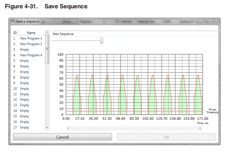
- Select a sequence ID or enter a new name for the sequence and click OK.
The message “Sequence was saved” appears.
To recall a Pulse Sequence:
- Select Sequence->Readfrom Laser.
- Select asequence ID and click OK.
The sequence is fetched and loaded into the chart.
On a Host PC
You can write Pulse Sequences to your computer to use and activate them in the Sequence Editor.
To save a Pulse Sequence your computer:
- Select Sequence-> Write to File.
- Enter a name for the file and click Save.
To recall a Pulse Sequence:
- Select Sequence->Read from File.
- Select a sequence ID and click OK.
The sequence is fetched and loaded into the chart.
Deleting a Pulse Sequence
You cannot delete a Pulse Sequence if the status is not “Idle.” When the status is “In Use” it means that the laser is configured with that Pulse Sequence.
To delete a Pulse Sequence:
- Select Sequence->Deletein Laser.
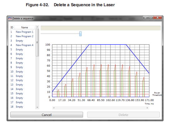
- Select a sequence ID to delete.
- Click Delete.
- Click Yes in the confirmation box.
Pulse Sequence Activation
To activate a Pulse Sequence:
- Click the Laser Control tab.
- Toggle the Waveform button to Enabled.
- Toggle the Waveform mode to Pulse Sequence.
- Select a Wave form sequence from the listbox.
- Click SET.
- Click Emission to confirm and start countdown.
The selected pulse is emitted after the countdown.
- Click Emission again to clear the status. This also stops a pulse sequence if it is set to infinite repeats.

Pulse Sequence Activation using the Touch-Screen Display
You can use the Touch-Screen Display on the laser’s front panel for manual control.You can view information about the laser’s state and settings.
After storing a Pulse Sequence to the laser, ensure the E-stop button is released on the laser. Then press the green button to turn on the power supply.
Both Analog and Modulation modes must be set to “Off” to correctly configure the Pulse Sequence mode. To change them, select Pulse Menu->Pulse Setting.
To activate a Pulse Sequence from the Touch-Screen Display on the laser:
- Select Pulse Menu->Pulse Setting->Waveform Mode.
- Toggle Wave form Pulse Mode to Enabled.
- Select Pulse Sequence.
- Use the Up and Down arrows to select aspecific Pulse Sequence.
- Pulse Sequence Information/Preview (Optional) -To view information about the Pulse Sequence, click on the Pulse Browser button. The information page appears. You can use the arrows to scroll through all available pages.
- Click anywhere in the text space to go to the Preview page.You can see the shape of the pulses in the sequence. Use the arrows to see the entire page.
- Click Return twice to go back to the Wave form page.
It is important to configure the laser with the selected pulse sequence (once)before usage.
- Click Configure& Return. After the configuration is complete, click Return twice to go back to the main page.
- Click Emission, and then click OK to confirm and start countdown.
The selected pulse is emitted after the countdown. Click Emission again to clear the status. This also stops a pulse sequence if it is set to infinite repeats.
Remote Control Interface
This interface is designed to provide remote control. It covers the pulse-shaping feature and it not meant to be a comprehensive control utility.
This interface works simultaneously with the Touch-Screen display.
To start the interface:
- Select Remote Control from the top menu.
- Use the Setup panel to enable the Wave form (pulse) mode.
- Select the pulse or sequence mode.
- Select apulse or sequence then configure the laser.
5 Troubleshooting
Error Messages on the Display and Status Bits
The following table lists errors and possible solutions, which are associated with the displayed errors on the touch-screen display or returned status bits via the RS-232connection.
Table 5-1. Error Messages with Possible Solutions
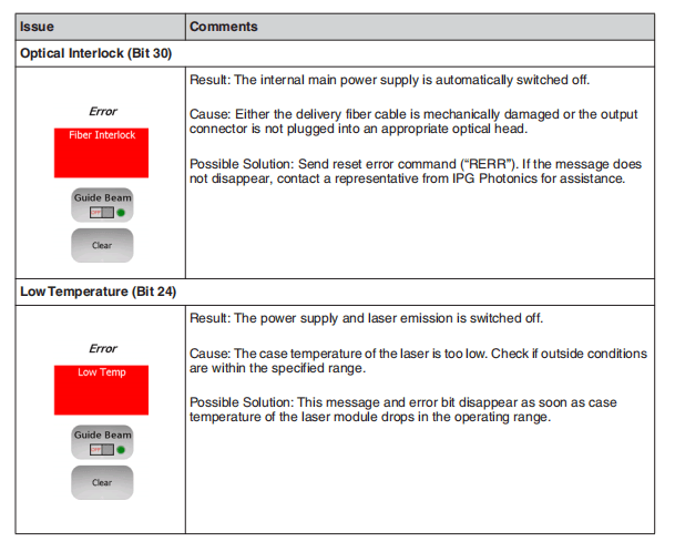
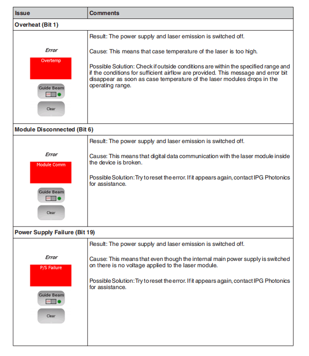
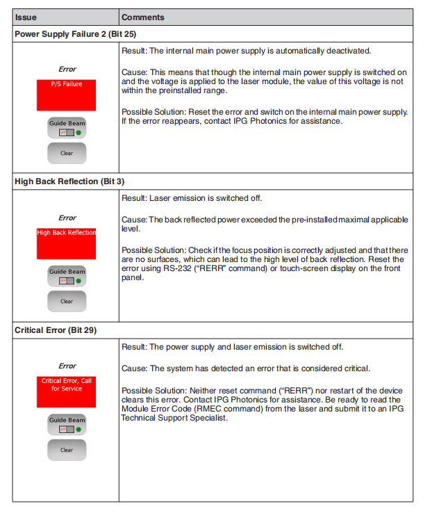


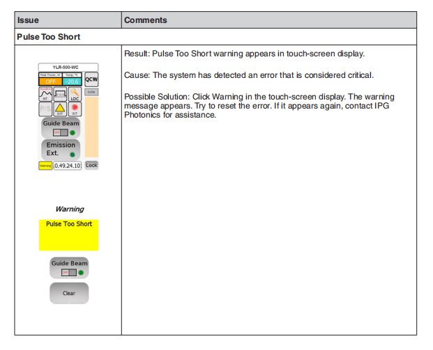
A Web User Utility
Overview
You can troubleshoot your laser using the IG337 Web User Utility, which provides status information and digital control functionality.
This appendix explains how to configure your computer’s communication protocols to connect to the laser via a PC.
Configuration Procedures
You can connect to the Web User Utility from either an Ethernet or RS-232 connection.
Configuring an Ethernet Connection
The following procedure assumes you are familiar with operating the YLM-QCW laser.
IPG recommends that you review all safety and operational procedures before proceeding.
- Connect PC to the laser using astandard Ethernet cable.
- Manually configure the LocalArea Connection settings for Ethernet (see “Configuring a LAN Connection for Ethernet” on page A-2).
- Openyour web browser and enter the IP address of the Internet Protocol. If the connection is successful, the IG337 Web User Utility page appears (as shown in Figure A-6).
Configuring an RS-232 Serial Connection
See “Connecting Using RS-232” on page 4-13 for step-by-step instructions.
Configuring a LAN Connection for Ethernet
To configure a LAN connection for Ethernet:
- Goto Control Panel -> Network and Internet -> Network and Sharing Center.
- Click Change adapter settings.
- Selecta Local Area Connection icon. The following window appears as shown in Figure A-1.
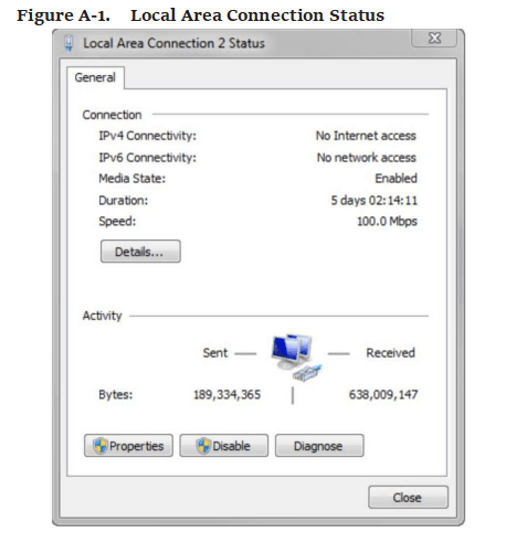
- Click Properties.The following window appears as shown in Figure A-2.
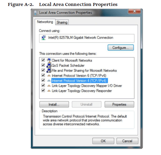
- Select Internet Protocol Version 4 (TCP/IPv4).
- Click Properties.The following window appears as shown in Figure A-3.
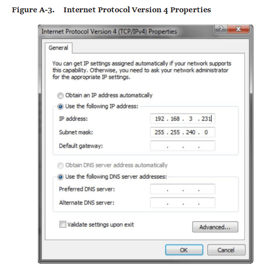
- Click the Use the following IP address radio button to manually assign the IP address.
- Assign the IP address to 192.168.3.23x (x cannot be 0as it is the default IP address of the Laser).
- Assign the Subnetmask to 255.255.240.0.
- Click OK to accept your changes.
Website Data Settings
To ensure the most current Web User Utility interface is downloaded to your web browser, you need to modify the Website data settings in Internet Explorer.
To modify the Website data settings:
- Open Internet Explorer.
- Select Tools -> Internet Options.
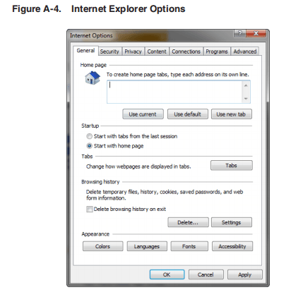
- Click Settings.
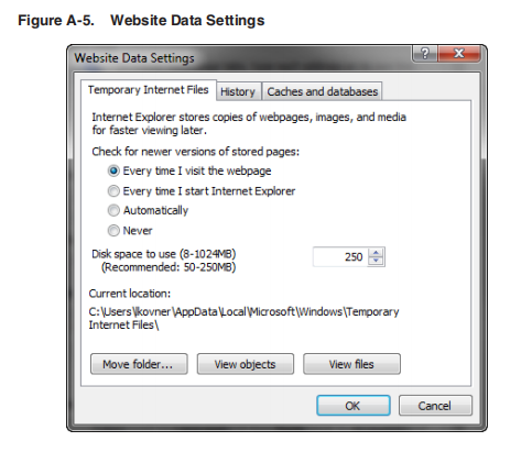
- Click EverytimeI visit the webpage.
- Click OKto save this setting.
Accessing the Web User Utility
To access Web Utility:
- Enterthe IP address of the laser in a web browser. The Web User utility appears.
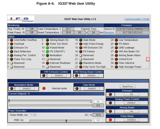
The items (0 to 31) in the Status group are listed in Table 3-5 on page 3-8 (Bit Meanings).
See Table 2-6 on page 2-19 for details on main control functions.
See Figure 2-13 on page 2-17 guidelines on setting the Pulse Generator.
- Click the Communication Configuration link at the top of the screen to change the IP address or baud rate. The following page appears.

- Clickthe Revision link to upload the latest laser module software version. The following page appears:

- Click the Ellipsisbutton (…) to reset critical errors. The following page appears:

- Provide the Serial Number,Counter, and Error Code to receive a reset code from IPG Customer Service.
- Turn on the Aiming Beam and verify that it is visible at the optical output.
B Service
Service and Repairs
There are no operator serviceable parts inside. Only the fuses and filter media arereplaceable. Refer all internal servicing to qualified IPG personnel.
Many issues and questions regarding the safety, set-up, operation and maintenanceof the IPG products can be resolved by reading this guide carefully.
However, if youhave questions regarding the safety, set-up, operation or maintenance of your IPGproduct, call the Customer Service department.
If you cannot resolve the issues by using this guide or over the telephone with a technical support representative, you might need to return the product to IPG. See“Product Returns” on page E-1 for more details.
Serviceable Items
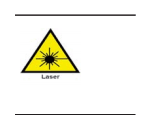
The unit should never be operated with any of the covers removed, including the front panel fan covers.
The input voltage to the laser is potentially lethal. All electrical cables and connections should be treated as if it were a harmful level. All parts of the electrical cable, connector or device housing should be considered dangerous.
This device is classified as a high power Class 4 laser instrument under 21 CFR 1040.10. This product emits invisible laser radiation at or around a wavelength of 1070 nm, and the total light power radiated from the optical output is greater than 20 to 1500 W (depending on model) per optical output port.
This level of light can cause damage to the eye and skin. Despite the radiation being invisible, the beam may cause irreversible damage to the cornea.
Laser safety eyewear is not provided with this instrument, but must be worn at all times while the laser is operational.
Service personnel should always follow correct Lockout/Tagout procedures per yourcompany’s policy to ensure all potential energy is removed from the system beforeservicing.
Replacing Fuses
Fuse Ratings: Refer to Table 18: Replacement Parts
To replace the main power fuses:
- Disconnect the power source and remove the keys from laser.
- Turn the laser so the rear panel is easily accessible.
- Locate the fuses and unscrew the covers.

Replace blown or damaged fuses with only the same amperage fuses. Replace the
fuse(s) and covers and tighten securely.
Replacing the Filter Media
Inspect the filter media weekly and clean or replace as needed. Only use IPG partswhen replace filter media.
To access the filters, use the following procedure:
- Unplug the line cord and remove keys from laser.
- Remove the front bezel on the front panel of the laser (refer to Figure 5: Front Panel ). Upon removal, the filter element will be exposed.
- Remove the used filter and clean or replace with anew filter (Refer to Table B-1).
- Snap the cover back on and dispose of the dirty filter element.
Table B-1. Replacement Parts
| Description | Laser Categorya | Part Number |
| Filter Media | 3U | P45-004679 |
| Filter Media | 4U | P45-004676 |
| Filter Media | 6U | P45-004679 and P45-004704 |
| Fuse T 10A 250VAC | 3U AC | P40-001743 |
| Fuse T 15A 250VAC | 3U WC, 4U AC (CW and QCW), 6U AC | P40-001564 |
- Refer to Laser Model Designation Codes
C Optical Fiber Connector Inspection and Cleaning
Overview
You should regularly check the fiber connector for dust, dirt, or damage before youconnect to any external optic. The use of a dirty, or improperly cleaned, fiberconnector can lead to serious damage to the laser (Figure C-6 on page C-7 illustratespossible fiber failures).
IPG Photonics is not responsible for any damages due to contaminated connectors.Tampering with the fiber connectors without training by IPG voids the warranty.
For cleaning a fiber connector, you need the following materials:
- Powder free rubber gloves or finger cots
- Lint free optical cleaning wipes and/or swabs
- Acetone (optical grade, water free)
- Compressed air (oil free, water free)
- Microscope (IPG model or equivalent)
- Light Source

You need to wear powder free rubber gloves during this cleaning procedure. Damage to the fiber connector can occur due to mishandling. The use of incorrect cleaning procedures or chemicals for cleaning is not covered by the warranty.
Acetone should be handled and stored in accordance to any local regulations (e.g. OSHA Regulation 29 CFR 1910.1200). Refer to each solvent’s MSDS (Material Safety Data Sheet) for additional information.
To clean the fiber connector:
- Switch off the laser main power by pressing the Emergency Stop button on the front of the unit and turning the Keyswitch to the center position.
- Leave protective cap on and clean the fiber connector exterior with opticalcleaner, wipe it with a clean optical wipe and dry with compressed air.
- Place fiber connector in the holder of the microscope.
- Place pressure on the center of the securing arm before tightening the locking screw as shown in Figure C-2.
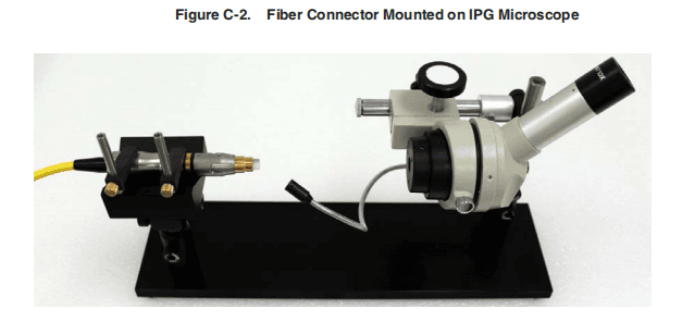
- Remove cap and sleeve from connector as shown in Figure C-3.
Place the cap face down on a clean surface. Placing the cap face down on a lint free wipe is the best choice if the surfaces are questionable.
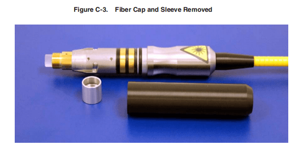
- Focus the microscope onto the connector surface.
- Use light source to illuminate the face of the connector so that the light is reflected from the surface of the microscope. This is achieved if you see a bright golden shine from the IPG (yellow cable) connector end-face or a blue surface for the connector (see Figure C-6 on page C-7).
Always look at the surface at a slight angle to improve visibility.
- Inspect the surface carefully.Any contamination might lead to dark spots on the surface and eventual fiber failure (see Figure C-6 on page C-7 for examples). Ifcontaminationisvisible on the quartz block,continue to the next step.Proceed to Step 14 if there is no contamination visible.
- Try to blow away the dust with compressed air from the side.
Never blow air directly at the surface because you could embed contaminants into the surface.
Always blow across the surface.
- While wearing powder free gloves, fold the lint free optical wipe into halves until it is roughly 1 X 1 ½” rectangle (see Figure C-4 on page C-5). Put a few drops of optical cleaner onto the lint free optical cleaning wipe on the folded edge of the wipe as indicated.
Do not ever reuse a lint free optical wipe or swab to clean the end face.
- Re-inspect the lens.
- Repeat step 10 withAcetone if lens is still contaminated.
- Ifnecessary, put a drop of Acetone onto a cleaning swab and gently wipe away contamination in a circular motion being careful not to scratch the lens. Then repeat from step 10.

Do not touch the tip of the cleaning swab with your fingers and use each swab onlyonce to prevent contamination.
- Repeat above cleaning steps until all contamination is removed. This cleaning procedure can be stopped at any time if a good result has already been achieved.
After fiber connector is clean use compressed air to clean the protective sleeve and install onto the connector.
Damage to the fiber connector can occur due to mishandling, the use of incorrect cleaning procedures, or chemicals for cleaning. This is not covered by the warranty.
- If the fiber is not to be connected immediately with asuitable optical component, use compressed air to clean the protection cap and install over the fiber end.
Make sure you clean the cap and sleeve before installing them back onto connector.
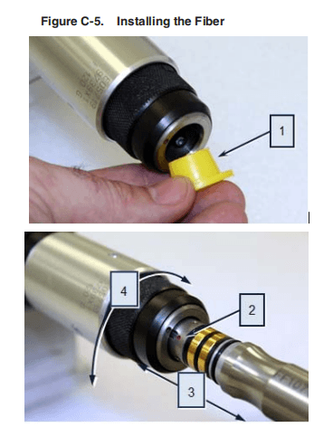
- Remove the plastic protection cap at the bayonet enclosure.
- For connecting the fiber to the bayonet, the red dot at the fiber has to be in line with the red dot at the bayonet enclosure.
- Gently slide the fiber all the way into the fiber port.
- Lock the fiber into place by rotating the bayonet knurled ring.
Hand tighten only as the use of tools can lead to damage to the bayonet enclosure.

D Warranty
Limited Express Product Warranties
IPG warrants to the original Buyer or, if Buyer is an authorized IPG reseller ordistributor, to Buyer’s original customer of the IPG Product, that the IPG Productconforms to applicable IPG Product specifications and is free from defects inmaterials and workmanship. These non-transferable warranties start on the shipmentdate from IPG (or other date specifically referencing the warranty start date in IPG’ssales order/order acknowledgement), and continue until the end of the warrantyperiod listed in IPG’s sales order/order acknowledgement. If there is no warrantyperiod listed, then warranty period is one year. Products or major componentsmanufactured by parties other than IPG bear the original manufacturer’s warrantyand warranty period. The obligations of IPG are limited to the repair or replacement(at IPG’s option) of any Product that does not meet the IPG warranty during thewarranty period. IPG warrants repaired or replaced Products under warranty onlyfor the remaining un-expired period of time in the original warranty. IPG reservesthe right to issue a credit note for any defective Products that have proved defectivethrough normal usage; Buyer debit memos are not allowed. This warranty governsover any conflicting terms in Buyer’s purchase order or other IPG documents exceptas expressly provided herein.
Warranty Limitations
This warranty excludes and does not cover defects or damage resulting from any of the following: contamination of external optical surfaces; unauthorized modification, misuse or mishandling, disassembly or opening, neglect, or damagefrom accident; operation outside environmental specifications or product ratings;user software or interfacing; components and accessories manufactured bycompanies other than IPG, which have separate warranties; improper or inadequateinstallation, site preparation or maintenance; or failure to follow information andprecautions contained in the operating manual. Additional warranty exceptions,limitations and exclusions may apply for laser systems manufactured by IPG and itsaffiliates as set forth in the applicable quotation and sales order/order acknowledgement. All products or components (including software) identified asexperimental, prototypes or to be used in field trials are not warranted and areprovided to the Buyer on an “as is” basis. IPG assumes no responsibility for Buyeror third-party supplied material, components, systems or equipment. Products andrepaired Products may contain components that have been previously used in other products, however such Products meet IPG Product specifications for newlymanufacturedProducts. The Buyer must give prompt notification to IPG of any claimunder the warranty in writing. IPG has no responsibility for warranty claims morethan 30 days after the Buyer discovers or becomes aware of the claimed defect.
Buyeris responsible for providing appropriate utilities and operating environment as statedin the operating manual and the specifications. This warranty applies only to theoriginal Buyer at the initial installation or delivery point. Buyer must make all claimsunder this warranty and no claim will be accepted from any third party.
EXCEPT FOR THE LIMITED WARRANTIES EXPRESSLY SET FORTHABOVE, IPG SPECIFICALLY DISCLAIMS ANY AND ALL OTHER WARRANTIES AND REPRESENTATIONS TO BUYER, INCLUDING WITHOUT LIMITATION, ANY AND ALL IMPLIED WARRANTIES, SUCH AS FREEDOM FROM INFRINGEMENT, MERCHANTABILITY AND FITNESS FOR A PARTICULAR PURPOSE.
Limitation of Remedies and Liabilities
THE REMEDIES PROVIDED HEREINARE BUYER’S SOLEAND EXCLUSIVE REMEDIES. IN NO EVENT SHALL IPG BE LIABLE FOR DIRECT, INDIRECT, SPECIAL, INCIDENTAL, CONSEQUENTIAL, EXEMPLARY OR PUNITIVE DAMAGES (EVEN IFADVISED OF THE POSSIBILITY OF SUCH DAMAGES)ARISING FROM OR RELATING TO THIS ORDER OR THE PRODUCTS (INCLUDING, LOSS OF PROFITS)WHETHER BASED ON CONTRACT, TORT OR ANY OTHER LEGAL THEORY. IPG’S MAXIMUM LIABILITY ARISING UNDER THESE TERMS AND CONDITIONS WILL NOT EXCEED, IN THEAGGREGATE, THE TOTAL AMOUNT PAID FOR THE PRODUCTS BY BUYER. THESE LIMITATIONS MAY NOT APPLY TO YOU UNDER THE LAWS OF CERTAIN JURISDICTIONS.
Software
Firmware License Agreement
CAREFULLY READ THE FOLLOWING TERMS AND CONDITIONS BEFORE OPENING THIS PACKAGE OR SIGNIFYING YOUR ACCEPTANCE BY CLICKING THEAPPROPRIATE DIALOG BOX. OPERATING THE PRODUCT, CLICKING THEAPPROPRIATE DIALOG BOX OR USINGANY PART OF THE SOFTWARE SIGNIFIES YOUR ACCEPTANCE OF THESE TERMS AND CONDITIONS. IF YOU DO NOT AGREE WITH THEM, PROMPTLY RETURNTHE PRODUCT UNUSED ALONG WITH ANY OTHER RELATED ITEMSTHAT WERE INCLUDED IN THE SAME ORDER FOR FULL CREDIT.
You, as the Customer, agree as follows:
- DEFINITIONS
“IPG” shall mean the IPG Photonics Corporation affiliate providing LicensedSoftware to Customer pursuant to this Agreement.
“IPG Software” shall mean those portions of the Licensed Software owned by IPGor IPG affiliates.
“Licensed Software” shall mean the software, in object code form only, supplied byIPG pursuant to this Agreement.
“Licensed Product” shall mean the Licensed Software and/or itsaccompanying documentation.
“Third Party Software” shall mean those portions of the Licensed Software owned or licensed by a third party, including but not limited to operating system code, thatis embedded within the Licensed Software.
- LICENSE
2.1 Except as provided in section 2.2 below, you are granted a non-transferable, nonexclusive license to use the Licensed Software only as embedded in or to be usedon a single IPG product.
You may copy the Licensed Product, for backup purposesonly, in support of your use of the Licensed Software, limited to one copy. No othercopies shall be made unless authorized in writing by IPG. You must reproduce andinclude all applicable copyright notices on any copy. You may not reverse compile or otherwise reverse engineer, or modify the Licensed Software. The Licensed Software, comprising proprietary trade secret information of IPG and/or its licensors, shall be held in confidence by Customer and Customer shall not disclose it to thirdparties, unless disclosure is required by law or legal process. In response to suchlegal requirements, the Customer shall promptly notify IPG in advance of such disclosure and reasonably cooperate in attempts to maintain the confidentiality of theLicensed Software. No title to the intellectual property is transferred.
Licensed Software shall not be copied, reproduced, or used for any other purpose outside ofoperation of the IPG product, and shall not be used on any other piece of hardwareother than the IPG product with which it was provided.
2.2 If you transfer the IPG product on which the Licensed Software is used, you may transfer the Licensed Software to the end user of the product provided that the end user agrees to be bound by terms no less restrictive than the provisions of this Agreement, and provided that all proprietary markings are maintained. Any other transfer is void and automatically terminates this license. You shall use your best efforts to enforce such agreement and shall promptly report any violation or suspected violation to IPG.
In the event you do not enforce such agreement after abreach, you shall, to the extent permissible by applicable law, grant IPG the right to enforce such agreement.
2.3 The Licensed Software may include Third Party Software licensed to IPG in addition to the licenses below. The owner of this Third Party Software (the “Third Party”) and its licensors are intended third party beneficiaries of thisAgreement, and the provisions of this Agreement relating to the Licensed Software, as the same incorporates Third Party Software, are made expressly for the benefit of, and are enforceable by, the Third Party and its licensors. The Third Party and its licensors retain ownership of all copies of the Third Party Software. The Licensed Software is warranted by IPG in accordance the above Warranty and the Third Party does not provide an additional warranty. All Third Party Software included in the Licensed Software is provided “AS IS” without warranty from the Third Party, and eachThird Party disclaims all warranties, either express or implied, including but not limited to the implied warranties of merchantability, title, non-infringementorfitness for a particular purpose with regard to the Third Party Software. The Third Party shall not have any liability for special, indirect, punitive, incidental or consequential damages.
2.4 The IPG Software is proprietary software not subjectto the GPL or LGPL or other open source license, and Customer has no license to take any action, and shall take no action, which would have the effect of subjectingthe IPG Software or any portion of the IPG Software to the terms of the GPL or LGPL or other open source license. Customer may consult the user documentation foridentifications and further information.
2.5 For the rights granted in this Agreement, Customer shall pay to IPG the pricefor the IPG hardware product in which the Licensed Software is embedded.
2.6 You understand that IPG may, at any time and in its sole discretion, update ormodify the Licensed Product or discontinue updating and/or supporting the LicensedProduct. In the case of an update or modification, you agree to allow IPG to automatically install the Licensed Software on the IPG hardware product on which the Licensed Software is used. Any updated or modified Licensed Product made available and/or installed by IPG on the IPG hardware product shall become part ofthe Licensed Software and subject to this Agreement.
- TERMAND TERMINATION
3.1 You may terminate the license granted hereunder at any time by destroying the Licensed Product together with all copies there of and notifying IPG in writing that all use of the Licensed Product has ceased and that same has been destroyed.
3.2 IPG may terminate this Agreement or any license hereunder upon notice to Customer if Customer breaches any of the terms and conditions of this Agreement or if Customer attempts to assign this Agreement or any license hereunder without IPG’s prior written consent. Within twenty (20) days after any termination of this Agreement, Customer shall certify in writing to IPG that all use of the Licensed Product has ceased, and that the same has been destroyed.
3.3 All provisions of this Agreement related to disclaimers of warranty, limitation of liability, IPG’s intellectual property rights, or export shall survive any expiration or termination and remain in effect. Termination of this Agreement orany license hereunder shall not relieve Customer of its obligation to pay any and all outstanding charges hereunder nor entitle Customer to any refund of such charges previously paid.
If your product includes LaserNet™ Software, the following applies:
Software License Agreement forLaserNet™
IPG Laser GmbH®
Single Use License
PLEASE READ THIS SOFTWARE LICENSE AGREEMENT (“LICENSE”) CAREFULLY BEFORE USING THE SOFTWARE OR THE EQUIPMENT. BY CLICKING ON THE “ACCEPT” BUTTON, USING THIS SOFTWARE, OR USING THE EQUIPMENT THAT CONTAINS THIS SOFTWARE, YOU ARE CONSENTING TO BE BOUND BY THIS AGREEMENT. IF YOU DO NOTAGREE TO ALL OF THE TERMS OF THIS AGREEMENT, CLICK THE “DO NOT ACCEPT” BUTTON AND THE INSTALLATION PROCESS WILL NOT CONTINUE, RETURN THE PRODUCT TO THE MANUFACTURER.
- General.The software, documentation and any fonts accompanying this Licensewhether on disk, in read only memory, on any other media or in any other form(collectively the “IPG Software”) are licensed, not sold, to you by IPG Laser GmbHand its affiliates (“IPG”) for use only under the terms of this License, and IPG reservesall rights not expressly granted to you. The rights granted herein are limited to IPG’sand its licensors’ intellectual property rights in the IPG Software and do not includeany other patents or intellectual property rights. You own the media on which theIPG Software is recorded but IPG and/or IPG’s licensor(s) retain ownership of theIPG Software itself. The terms of this License will govern any software upgrades provided by IPG that replace and/or supplement the original IPG Software product,unless such upgrade is accompanied by a separate license in which case the terms ofthat license will govern.
- Permitted License Uses and Restrictions.
- This License allows you to install and use one copy of the IPG Software on asingle computer at a time. This License does not allow the IPG Software to exist on more than one computer at a time, and you may not make the IPG Software available over a net work where it could be used by multiple computers at the same time. You may make one copy of the IPG Software in machine-readable form for backup purposes only; provided that the backup copy must include all copyright or other proprietary notices contained on the original.
- Exceptas and only to the extent permitted in this License and by applicable law,you may not copy, decompile, reverse engineer, disassemble, modify, or createderivative works of the IPG Software or any part thereof. THE IPG SOFTWARE ISNOT INTENDED FOR USE IN THE OPERATION OF NUCLEAR FACILITIES,
AIRCRAFT NAVIGATION OR COMMUNICATION SYSTEMS, AIR TRAFFIC CONTROL SYSTEMS, OR OTHER EQUIPMENT IN WHICH THE MALFUNTION OF THE IPG SOFTWARE WOULD RESULT IN THE FORESEEABLE RISK OF INJURY OR DEATH TO THE OPERATOR OF THE EQUIPMENT OR SYSTEM OR TO OTHERS.
- Transfer.You may not rent, lease, lend, redistribute or sublicense the IPGSoftware. You may, however, make a one-time permanent transfer of all of yourlicense rights to the IPG Software (in its original form as provided by IPG) to anotherparty, provided that: (a) the transfer must include all of the IPG Software, includingall its component parts, original media, printed materials and this License; (b) you do not retain any copies of the IPG Software, full or partial, including copies storedon a computer or other storage device; and (c) the party receiving the IPG Softwarereads and agrees to accept the terms and conditions of this License.
- Termination.This License is effective until terminated. Your rights under this License will terminate automatically without notice from IPG if you fail to complywith any term(s) of this License. Upon the termination of this License, you shall ceaseall use of the IPG Software and destroy all copies, full or partial, of the IPG Software.
- LimitedWarranty on Media. IPG warrants the media on which the IPG Software is recorded and delivered by IPG to be free from defects in materials and workmanship under normal use for a period of ninety (90) days from the date of original purchase. Your exclusive remedy under this Section shall be, at IPG’s option, replacement of the IPG Software which is returned to IPG or an IPG authorized representative. THIS LIMITED WARRANTY AND ANY IMPLIED WARRANTIES ON THE MEDIA INCLUDING, BUT NOT LIMITED TO, THE IMPLIED WARRANTIES OF MERCHANTABILITY, OF SATISFACTORY QUALITY, AND OF FITNESS FOR A PARTICULAR PURPOSE,ARE LIMITED IN DURATION TO NINETY (90) DAYS FROM THE DATE OF ORIGINAL PURCHASE.
- Disclaimer of Warranties. YOU EXPRESSLY ACKNOWLEDGE AND AGREE THAT USE OF THE IPG SOFTWARE IS AT YOUR SOLE RISK AND THAT THE ENTIRE RISK AS TO SATISFACTORY QUALITY, PERFORMANCE, ACCURACY AND EFFORT IS WITH YOU.
EXCEPT FOR THE LIMITED WARRANTY ON MEDIA SET FORTH ABOVE AND TO THE MAXIMUM EXTENT PERMITTED BY APPLICABLE LAW, THE IPG SOFTWARE IS PROVIDED “AS IS”, WITH ALL FAULTS AND WITHOUT WARRANTY OF ANY KIND TO THE FULLEST EXTENT PERMITTED BY APPLICABLE LAW, IPG AND ITS SUPPLIERS FURTHER DISCLAIM ALL WARRANTIES, EXPRESS OR IMPLIED, INCLUDING, WITHOUT LIMITATION, IMPLIED WARRANTIES OF TITLE, NON- INFRINGEMENT,ACCURACY, MERCHANTABILITY, AND FITNESS FOR A PARTICULAR PURPOSE, AND ANY WARRANTIES THAT MAY ARISE FROM COURSE OF DEALING, COURSE OF PERFORMANCE, OR TRADE PRACTICE.
THE ENTIRE RISK ARISING OUT OF THE USE OR PERFORMANCE OF THE IPG SOFTWARE OR RELATED MATERIALS REMAINS WITH YOU.APPLICABLE LAW MAY NOT ALLOW THE EXCLUSION OF IMPLIED WARRANTIES, SO THE ABOVE EXCLUSIONS MAY NOT APPLY TO YOU. IPG MAY MAKE CHANGES TO THE IPG SOFTWARE AND HAS NO OBLIGATION TO DISTRIBUTE NEWER VERSIONS.
- Limitation of Liability. NEITHER IPG NOR ANY OF ITS SUPPLIERS SHALL BE RESPONSIBLE OR LIABLE FOR ANY INDIRECT, INCIDENTAL, CONSEQUENTIAL, SPECIAL, EXEMPLARY, PUNITIVE OR OTHER DAMAGES (INCLUDING, WITHOUT LIMITATION, DAMAGES FOR LOSS OF BUSINESS, LOSS OF DATA OR LOST PROFITS), UNDER ANY CONTRACT, NEGLIGENCE, STRICT LIABILITY OR OTHER THEORYARISING OUT OF OR RELATING IN ANY WAY TO THE IPG SOFTWARE EVEN IF IPG OR ITS SUPPLIERS HAVE BEEN ADVISED OF THE POSSIBILITY OF SUCH DAMAGES. YOUR SOLE REMEDY FOR DISSATISFACTION WITH THE IPG SOFTWARE IS TO STOP USING THE IPG SOFTWARE. THE SOLE AND EXCLUSIVE MAXIMUM LIABILITY TO IPG FOR ALL DAMAGES, LOSSES AND CAUSES OF ACTION, WHETHER IN CONTRACT, TORT (INCLUDING, WITHOUT LIMITATION, NEGLIGENCE) OR OTHERWISE, SHALL BE THE TOTAL AMOUNT PAID BY YOU, IF ANY, FOR USE OF THE IPG SOFTWARE. THESE LIMITATIONS MAY NOT APPLY TO YOU UNDER THE LAWS OF CERTAIN JURISDICTIONS.
The foregoing limitations will apply even if the above stated remedy fails of itsessential purpose.
- ExportLawAssurances. You acknowledge that IPG Software is subject to U.S.and European Union export jurisdiction. You agree to comply with all applicableinternational and national laws that apply to the IPG Software, including the U.S.Export Administration Regulations, as well as end-user, end-use and destinationrestrictions issued by U.S. and other governments.
- Government End Users.The IPG Software and related documentation are”Commercial Items”, as that term is defined at 48 C.F.R. §2.101, consisting of”Commercial Computer Software” and “Commercial Computer SoftwareDocumentation”, as such terms are used in 48 C.F.R. §12.212 or 48 C.F.R. §227.7202,as applicable. Consistent with 48 C.F.R. §12.212 or 48 C.F.R. §227.7202-1 through
227.7202-4, as applicable, the Commercial Computer Software and Commercial Computer Software Documentation are being licensed to U.S. Government end users(a) only as Commercial Items and (b) with only those rights as are granted to all otherend users pursuant to the terms and conditions herein. Unpublished-rights reservedunder the copyright laws of the United States.
- Controlling Law and Severability.This License will be governed by and construed in accordance with the laws of the State of Massachusetts, as applied to agreements entered into and to be performed entirely within Massachusetts between Massachusetts residents. This License shall not be governed by the United NationsConvention on Contracts for the International Sale of Goods, the application of whichis expressly excluded. If for any reason a court of competent jurisdiction finds anyprovision, or portion thereof, to be unenforceable, the remainder of this License shallcontinue in full force and effect.
- CompleteAgreement;Governing Language. This License constitutes the entireagreement between the parties with respect to the use of the IPG Software licensed hereunder and supersedes all prior or contemporaneous understandings regardingsuch subject matter. No amendment to or modification of this License will be bindingunless in writing and signed by IPG. Any translation of this License is done for localrequirements and in the event of a dispute between the English and any non-Englishversions, the English version of this License shall govern.
If your product includes Microsoft Corporation embedded software, then the following applies:
MICROSOFT CORPORATIONEMBEDDED SOFTWARE
END USER LICENSE AGREEMENT
You have acquired a device (“EQUIPMENT”) that includes software licensed by IPG Photonics Corporation or its affiliates (collectively, “IPG”) from an affiliate of Microsoft Corporation (“MS”). Those installed software products of MS origin, as well as associated media, printed materials, and “online” or electronic documentation (“SOFTWARE”) are protected by international intellectual property laws and treaties. IPG, MS and its suppliers (including Microsoft Corporation) own the title, copyright, and other intellectual property rights in the SOFTWARE.
The SOFTWARE is licensed, not sold. All rights reserved.
IF YOU DO NOT AGREE TO THIS END USER LICENSE AGREEMENT (“EULA”), DO NOT USE THE EQUIPMENT OR COPY THE SOFTWARE.
INSTEAD, PROMPTLY CONTACT IPG FOR INSTRUCTIONS ON RETURN OFTHE UNUSED EQUIPMENT(S) FOR A REFUND.
ANY USE OF THE SOFTWARE, INCLUDING BUT NOT LIMITED TO USE OF THE EQUIPMENT, WILL CONSTITUTE YOUR AGREEMENT TO THIS EULA (OR RATIFICATION OF ANY PREVIOUS CONSENT).
This EULA is valid and grants the end-user rights ONLY if the SOFTWARE is genuine and a genuine Certificate of Authenticity for the SOFTWARE is included.
GRANT OF SOFTWARE LICENSE. This EULA grants you the following license:
- Youmay use the SOFTWARE only on the EQUIPMENT.
- Restricted Functionality.You are licensed to use the SOFTWARE to provideonly the limited functionality (specific tasks or processes) for which the EQUIPMENT has been designed and marketed by IPG. This license specificallyprohibits any other use of the software programs or functions, or inclusion ofadditional software programs or functions that do not directly support the limited functionality on the EQUIPMENT. Notwithstanding the foregoing, you may installor enable on a EQUIPMENT, systems utilities, resource management or similar software solely for the purpose of administration, performance enhancement and/orpreventive maintenance of the EQUIPMENT.
- If you use the EQUIPMENT to access or utilize the services or functionality of Microsoft Windows Server products (such as Microsoft Windows Server 2003), oruse the EQUIPMENT to permit workstation or computing devices to access or utilize
the services or functionality of Microsoft Windows Server products, you may berequired to obtain a Client Access License for the EQUIPMENT and/or each suchworkstation or computing device. Please refer to the end user license agreement foryour Microsoft Windows Server product for additional information.
- NOT FAULTTOLERANT. THE SOFTWARE IS NOT FAULT TOLERANT.IPG HAS INDEPENDENTLY DETERMINED HOW TO USE THE SOFTWAREIN THE EQUIPMENT, AND MS HAS RELIED UPON IPG TO CONDUCTSUFFICIENT TESTING TO DETERMINE THAT THE SOFTWARE ISSUITABLE FOR SUCH USE.
- NO WARRANTIES FOR THE SOFTWARE. THE SOFTWARE is provided “AS IS” and with all faults. THE ENTIRE RISK AS TO SATISFACTORY QUALITY, PERFORMANCE,ACCURACY,AND EFFORT (INCLUDING LACK OF NEGLIGENCE) IS WITH YOU. ALSO, THERE IS NO WARRANTYAGAINST INTERFERENCE WITH YOUR ENJOYMENT OF THE SOFTWARE OR AGAINST INFRINGEMENT. IF YOU HAVE RECEIVED ANY WARRANTIES REGARDING THE EQUIPMENT OR THE SOFTWARE, THOSE WARRANTIES DO NOT ORIGINATE FROM, AND ARE NOT BINDING ON, MS.
- No Liability for Certain Damages. EXCEPT AS PROHIBITED BY LAW, MS SHALL HAVE NO LIABILITY FOR ANY INDIRECT, SPECIAL, CONSEQUENTIAL OR INCIDENTAL DAMAGES ARISING FROM OR IN CONNECTION WITH THE USE OR PERFORMANCE OF THE SOFTWARE. THIS LIMITATION SHALL APPLY EVEN IF ANY REMEDY FAILS OF ITS ESSENTIAL PURPOSE. IN NO EVENT SHALL MS BE LIABLE FOR ANYAMOUNT IN EXCESS OF U.S. TWO HUNDRED FIFTY DOLLARS (U.S.$250.00).
- RestrictedUses. The SOFTWARE is not designed or intended for use or resalein hazardous environments requiring fail-safe performance, such as in the operationof nuclear facilities, aircraft navigation or communication systems, air traffic control,or other devices or systems in which a malfunction of the SOFTWARE would resultin foreseeable risk of injury or death to the operator of the equipment or system, orto others.
- Limitationson Reverse Engineering, Decompilation, and Disassembly. You may not reverse engineer, decompile, or disassemble the SOFTWARE, except and onlyto the extent that such activity is expressly permitted by applicable law not withstanding this limitation.
- SOFTWARE as a Component of the Equipment-Transfer. This license may notbe shared, transferred to or used concurrently on different computers. The SOFTWARE is licensed with the EQUIPMENT as a single integrated product and may only be used with the EQUIPMENT. If the SOFTWARE is not accompanied by EQUIPMENT, you may not use the SOFTWARE.
You may permanently transfer all of your rights under this EULA only as part of a permanent sale or transfer of theEQUIPMENT, provided you retain no copies of the SOFTWARE. If the SOFTWARE is an upgrade, any transfer must also include all prior versions of the SOFTWARE. This transfer must also include the Certificate of Authenticity label.The transfer may not he an indirect transfer, such as a consignment. Prior to the transfer, the end user receiving the SOFTWARE must agree to all the EULA terms.
- Consent to Use of Data.You agree that MS, Microsoft Corporation and their affiliates may collect and use technical information gathered in any manner as partof product support services related to the SOFTWARE. MS, Microsoft Corporationand their affiliates may use this information solely to improve their products or to provide customized services or technologies to you. MS, Microsoft Corporation and their affiliates may disclose this information to others, but not in a form that personally identifies you.
- Internet Gaming/Update Features. If the SOFTWARE provides, and you chooseto utilize, the Internet gaming or update features within the SOFTWARE, it isnecessary to use certain computer system, hardware, and software information to implement the features. By using these features, you explicitly authorize MS,Microsoft Corporation and/or their designated agent to use this information solely to improve their products or to provide customized services or technologies to you. MSor Microsoft Corporation may disclose this information to others, but not in a formthat personally identifies you.
- Internet-Based Services Components.The SOFTWARE may containcomponents that enable and facilitate the use of certain Internet-based services. Youacknowledge and agree that MS, Microsoft Corporation or their affiliates may automatically check the version of the SOFTWARE and/or its components that youare utilizing and may provide upgrades or supplements to the SOFTWARE that maybe automatically downloaded to your EQUIPMENT. Microsoft Corporation or their affiliates do not use these features to collect any information that will be used to identify you or contact you.
- Links toThird Party Sites. You may link to third party sites through the use of the SOFTWARE. The third party sites are not under the control of MS or Microsoft Corporation, and MS or Microsoft are not responsible for the contents of any thirdparty sites, any links contained in third party sites, or any changes or updates to thirdparty sites. MS or Microsoft Corporation is not responsible for webcasting or any other form of transmission received from any third party sites. MS or Microsoft Corporation are providing these links to third party sites to you only as a convenience, and the inclusion of any link does not imply an endorsement by MS or MicrosoftCorporation of the third party site.
- Notice Regarding Security. Tohelp protect against breaches of security andmalicious software, periodically back up your data and system information, usesecurity features such as firewalls, and install and use security updates.
- No Rental/Commercial Hosting.You may not rent, lease, lend or providecommercial hosting services with the SOFTWARE to others.
- Separationof Components. The SOFTWARE is licensed as a single product. Itscomponent parts may not be separated for use on more than one computer.
- Additional Software/Services. This EULA applies to updates, supplements, add- on components, product support services, or Internet-based services components (“Supplemental Components”), of the SOFTWARE that you may obtain from IPG, MS, Microsoft Corporation or their subsidiaries after the date you obtain your initial copy of the SOFTWARE, unless you accept updated terms or another agreement governs. If other terms are not provided along with such Supplemental Components and the Supplemental Components are provided to you by MS, Microsoft Corporation or their subsidiaries then you will be licensed by such entity under the same terms and conditions of this EULA, except that (i) MS, Microsoft Corporation or their subsidiaries providing the Supplemental Components will be the licensor with respect to such Supplemental Components in lieu of the “COMPANY” for the purposes of the EULA, and (ii) TO THE MAXIMUM EXTENT PERMITTED BYAPPUCABLE LAW, THE SUPPLEMENTAL COMPONENTS AND ANY (IFANY) SUPPORT SERVICES RELATED TO THE SUPPLEMENTAL COMPONENTS ARE PROVIDED AS IS AND WITH ALL FAULTS. ALL OTHER DISCLAIMERS, LIMITATION OF DAMAGES, AND SPECIAL PROVISIONS PROVIDED BELOW AND/OR OTHERWISE WITH THE SOFTWARE SHALL APPLY TO SUCH SUPPLEMENTAL COMPONENTS. MS, Microsoft Corporation or their subsidiaries reserve the right to discontinue any Internet-based services provided to you or made available to you through the use of the SOFTWARE.
- Recovery Media. If SOFTWAREis provided by IPG on separate media andlabeled “Recovery Media” you may use the Recovery Media solely to restore orreinstall the SOFTWARE originally installed on the EQUIPMENT.
- Backup Copy.You may make one (1) backup copy of the SOFTWARE. Youmay use this backup copy solely for your archival purposes and to reinstall theSOFTWARE on the EQUIPMENT. Except as expressly provided in this EULA orby local law, you may not otherwise make copies of the SOFTWARE, including theprinted materials accompanying the SOFTWARE. You may not loan, rent, lend orotherwise transfer the backup copy to another user.
- EndUser Proof of License. If you acquired the SOFTWARE on a EQUIPMENT,or on a compact disc or other media, a genuine Microsoft “Proof of License”/Certificate of Authenticity label with a genuine copy of the SOFTWARE identifies
a licensed copy of the SOFTWARE. To be valid, the label must be affixed to theEQUIPMENT, or appear on IPG’s software packaging. If you receive the labelseparately other than from IPG, it is invalid. You should keep the label on theEQUIPMENT or packaging to prove that you are licensed to use the SOFTWARE
- ProductSupport. Product support for the SOFTWARE is not provided by MS,Microsoft Corporation, or their affiliates or subsidiaries. For product support, pleaserefer to IPG support number provided in the documentation for the EQUIPMENT.Should you have any questions concerning this EULA, or if you desire to contactIPG for any other reason, please refer to the address provided in the documentation for the EQUIPMENT.
- Termination.Without prejudice to any other rights, IPG may terminate this EULA if you fail to comply with the terms and conditions of this EULA. In suchevent, you must destroy all copies of the SOFTWARE and all of its component parts.
- EXPORTRESTRICTIONS. You acknowledge that SOFTWARE is subject to U.S. and European Union export jurisdiction. You agree to comply with all applicable international and national laws that apply to the SOFTWARE, including the U.S.Export Administration Regulations, as well as end-user, end-use and destination restrictions issued by U.S. and other governments.
E Product Returns
Returns to the United States
All product returns require a Return Merchandise Authorization (RMA) from IPG.
If you return a product with a RMA, please perform the following procedure:
- Products must be carefully packed in a suitable shipping container(s). Buyer assumes all responsibility for products damaged in shipment to IPG.
- Buyer must issue a purchase order for the value of the replaced parts/serviceitems and IPG will issue credit or invoice when the parts/service is received. Speak to IPG Service Manager for the amount authorized under the required purchase order.
- Allrequests for repair or replacement under this warranty must be made to IPG within 30 days after discovery of the defect (but not later than 7 days after warranty expiration).
- All products returned to IPG but which meet applicable specifications, not defectively manufactured or used not in accordance with this User’s Guide, will result in the Buyer being charged IPG’s standard examination charge.
- Complete packing list with product model and serial number will ensure prompt repair.
- Be sure to include with the returned product your ‘ship to’ address for the return of the serviced product.
F Glossary
°C Degrees centigrade or Celsius
°F Degrees Fahrenheit
l Lambda (wavelength symbol)
μs Microsecond = 10-6 second
Amp Amperes
AC Alternating current
ADC Analog-to-digital converter
ASCII American Standard Code for Information Interchange (U.S. Government)
BTU British thermal unit
CAN Controller Area Network
CDRH Center for Devices and Radiological Health (U.S. Government)
CFR Code of Federal Regulation (U.S. Government)
cm Centimeters = 10-2 meters
CPU Central processing unit
CW Continuous wave (operating mode)
DC Direct current
EN European Norm
Hz Hertz or cycles per second (frequency)
kg Kilograms
kV Kilovolts = 103 volts
kW Kilowatts = 103 watts
l Liters (volume)
lbs Pounds
IP Internet protocol
LD Laser diode
LCD Liquid crystal display
LED Light emitting diode
nm Nanometer = 10-9 meters
mA Milliamps = 10-3 amperes
mm Millimeter = 10-6 meters
MHz Megahertz = 106 Hertz
mrad Milliradian = 10-3 radians (geometry)
rms Root mean square or quadratic mean
QCW Quasi-Continuous wave (operating mode)
TCP Transmission control protocol
VAC Voltage alternating current
VDC Volts Direct Current
W Watts (power)
Index
Numerics
7-pin connector pinouts … 2-23
L
Laser Model Designation Codes … 2-1
Local Control Mode … 2-4, 2-29
C
Certification … 2-3
cleaning procedures … C-1
Collimator … 2-10
Connecting Electrical Power … 2-16
Continuous (CW) Operation Mode … 2-31
Control Modes
Local Mode … 2-29
Remote Mode … 2-29
E
Emission On Indicator … 2-4
Emission-On Indicator … 1-13
E-Stop button … 2-4
Ethernet TCP/IP Interface … 3-1
External (Analog) Power Control … 2-32
M
Model Configurations … 2-1
model specifications … 2-10
Modulation Mode … 2-32
O
Operation Control Modes … 2-29
Operation Modes
Continuous (CW) … 2-31
Pulsed (QCW) … 2-31
Operation Sub-Modes … 2-32
Optical Fiber Connector Inspection and Cleaning … C-1
Optical Output Fiber Terminations … 2-9
systems with a collimator … 2-10
systems with a connector … 2-9
F
filter media … B-2
front panel view … 2-3, 2-4
Functional Safety … 1-4
fuses … B-2
G
Gate Mode … 2-32
I
Initial Power-Up Sequence … 2-24
Interface Commands … 3-2
Interface Wire Specification … 2-17
Interlock Safety Circuit … 2-18
K
Key Control … 2-24
Keyswitch … 2-4
P
Product Returns … E-1
Pulse Shaper
Ethernet connection … 4-12
exporting … 4-15
importing … 4-15
installing … 4-4
menus … 4-18
Offline option … 4-14
RS-232 connection … 4-13
Pulse Waveform … 2-33
Pulsed (QCW) Operation Mode … 2-31
R
rear panel view … 2-6, 2-7
Remote Control Mode … 2-4, 2-29
replacing filter media … B-2
replacing fuses … B-2
returns … E-1
RS-232 Configuration … 3-1
S
Sequence Editing … 4-39
Service and Repairs … B-1
Standalone Mode … 2-32
system timing … 2-25
T
Touch-Screen Display … 2-4, 2-33
Troubleshooting … 5-1
U
Unpacking Instructions … 2-11
cardboard box … 2-11
wood crate … 2-14
Y
YLR-Series System using … 2-16