
Hypertherm Powermax 125a Plasma Arc Cutting System Operator Manual

Powermax125
Operator Manual
808080
Revision 0
English
Contents
Electromagnetic Compatibility (EMC)
Introduction
Installation and use
Assessment of area
Methods of reducing emissions
Mains supply
Maintenance of cutting equipment
Cutting cables
Equipotential bonding
Earthing of the workpiece
Screening and shielding
Warranty
Attention
General
Patent indemnity
Limitation of liability
National and local codes
Liability cap
Insurance
Transfer of rights
1 Specifications
Safety information
Powermax125 System description
Power supply dimensions
Component weights (125 A systems)
Hypertherm power supply ratings
Duramax Hyamp 85° hand torch dimensions
Duramax Hyamp 15° hand torch dimensions
Duramax Hyamp 180° full-length machine torch dimensions
Duramax Hyamp 180° mini machine torch dimensions
Powermax125 cutting specifications
Symbols and markings
Noise levels
IEC symbols
2 Power Supply Setup
Unpack the Powermax system
Claims
Contents
Position the power supply
Prepare the electrical power
Install a line-disconnect switch
Requirements for grounding
Power connection for the Powermax125
Three-phase power cord and plug installation
Extension cord recommendations
Engine-driven generator recommendations
Prepare the gas supply
Additional gas filtration
Connect the gas supply
Minimum inlet pressure (while gas is flowing)
Gas flow rates
3 Basic System Operations
Controls and indicators
Rear controls
Front controls and LEDs
LEDs
Selectors
Operating mode switch
Amperage adjustment knob
Status screen
Gas pressure indicators
System status icons
Fault codes and icons
Operating the Powermax
Connect the electrical power, gas supply, and torch lead
Attach the work lead to the power supply
Attach the ground clamp to the workpiece
Turn on the system
Set the operating mode switch
Check the indicators
Manually adjusting the gas pressure
Adjusting the current (amperage)
Electrode end-of-life detection feature
Understanding duty-cycle limitations
4 Hand Torch Setup
Introduction
Consumable life
Hand torch components
Duramax Hyamp 85° hand torch
Duramax Hyamp 15° hand torch
Choose the hand torch consumables
Drag-cutting 105/125 A consumables
Drag-cutting 45 A and 65 A consumables
Gouging consumables
FineCut consumables
Install the hand torch consumables
Connecting the torch lead
5 Hand Cutting
Using the hand torch
Operate the safety trigger
Hand torch cutting guidelines
Start a cut from the edge of the workpiece
Pierce a workpiece
Gouge a workpiece
Gouge profile
Varying the gouge profile
125 A gouging profile chart
Common hand-cutting faults
6 Machine Torch Setup
Introduction
Consumable life
Machine torch components
Duramax Hyamp 180° machine torch
Duramax Hyamp 180° mini machine torch
Disassemble the machine torch
Convert a full-length machine torch to a mini machine torch
Mount the torch
Choose the machine torch consumables
Machine torch consumables
Mechanized shielded 105 A/125 A consumables
Mechanized shielded 45 A and 65 A consumables
Mechanized shielded with ohmic 105 A/125 A consumables
Mechanized shielded with ohmic 45 A and 65 A consumables
Gouging consumables
FineCut shielded consumables
FineCut shielded with ohmic consumables
Install the machine torch consumables
Aligning the torch
Connecting the torch lead
Using the cut charts
Estimated kerf-width compensation
Estimated kerf-width compensation – Metric (mm)
Estimated kerf-width compensation – English (inches)
125 A shielded consumables
125 A shielded cutting – mild steel
125 A shielded cutting – stainless steel
125 A shielded cutting – aluminum
105 A shielded consumables
105 A shielded cutting – mild steel
105 A shielded cutting – stainless steel
105 A shielded cutting – aluminum
65 A shielded consumables
65 A shielded cutting – mild steel
65 A shielded cutting – stainless steel
65 A shielded cutting – aluminum
45 A shielded consumables
45 A shielded cutting – mild steel
45 A shielded cutting – stainless steel
45 A shielded cutting – aluminum
FineCut consumables
FineCut – mild steel
FineCut – stainless steel
7 Mechanized Cutting
Connecting an optional remote-start pendant
Connecting the machine interface cable
Machine interface pinout
Setting the five-position voltage divider
Accessing raw arc voltage
Connecting an optional RS-485 serial interface cable
Serial port cables
Using the machine torch
Setting up the torch and table
Understand and optimize cut quality
Cut or bevel angle
Dross
Piercing a workpiece using the machine torch
Common machine-cutting faults
8 Maintenance and Repair
Perform routine maintenance
Routine maintenance tasks
Inspect the Powermax125 consumables
Basic troubleshooting
Troubleshooting guide
Fault codes and solutions
Fault codes
Display the service screen
Run a gas test
Replace the gas filter element
9 Parts
Power supply parts
Exterior, front
Exterior, rear
Interior, fan side
Duramax Hyamp 85° hand torch replacement parts
Duramax Hyamp 15° hand torch replacement parts
Hand torch consumables
Drag cutting
Gouging
FineCut
Duramax Hyamp 180° full-length machine torch replacement parts
Duramax Hyamp 180° mini machine torch replacement parts
Machine torch consumables
Shielded
Gouging
FineCut
Accessory parts
Powermax125 labels
Introduction
Hypertherm’s CE-marked equipment is built in compliance
with standard EN60974-10. The equipment should be
installed and used in accordance with the information
below to achieve electromagnetic compatibility.
The limits required by EN60974-10 may not be adequate
to completely eliminate interference when the affected
equipment is in close proximity or has a high degree of
sensitivity. In such cases it may be necessary to use other
measures to further reduce interference.
This cutting equipment is designed for use only in an
industrial environment.
- Other supply cables, control cables, signaling and
telephone cables; above, below and adjacent to the
cutting equipment.
- Radio and television transmitters andreceivers.
- Computer and other controlequipment.
- Safetycritical equipment, for example guarding of
industrial equipment.
- Health of the people around, for examplethe use of
pacemakers and hearing aids.
- Equipment used for calibration or measurement.
Installation and use
The user is responsible for installing and using the plasma equipment according to the manufacturer’s instructions.
If electromagnetic disturbances are detected then it shall be the responsibility of the user to resolve the situation with the technical assistance of the manufacturer. In some cases this remedial action may be as simple as earthing the cutting circuit, see Earthing of the work piece.
In other cases, it could involve constructing an electromagnetic screen enclosing the power source and the work complete with associated input filters. In all cases, electromagnetic disturbances must be reduced to the point where they are no longer troublesome.
- Immunity of other equipment in the environment. User shall ensure that other equipment being used in the environment is compatible. This may require additional protection measures.
- Time of day that cutting or other activities are to be carried out. The size of the surrounding area to be considered will depend on the structure of the building and other activities that are taking place. The surrounding area may extend beyond the boundaries of the premises.
Methods of reducing emissions
Assessment of area
Before installing the equipment, the user shall make an
assessment of potential electromagnetic problems in the
surrounding area. The following shall be taken into account:
Mains supply
Cutting equipment must be connected to the mains
supply according to the manufacturer’s recommendations.
If interference occurs, it may be necessary to take
additional precautions such as filtering of the mains supply.
Consideration should be given to shielding the supply cable of permanently
installed cutting equipment, inmetallic conduit or equivalent. Shielding
should beelectrically continuous throughout its length.
The shieldingshould be connected to the cutting mains supply so that
good electrical contact is maintained between the conduitand the cutting
power source enclosure.
Maintenance of cutting equipment
The cutting equipment must be routinely maintained
according to the manufacturer’s recommendations. All
access and service doors and covers should be closed
and properly fastened when the cutting equipment is in
operation. The cutting equipment should not be modified
in any way, except as set forth in and in accordance with
the manufacturer’s written instructions. For example, the
spark gaps of arc striking and stabilizing devices should
be adjusted and maintained according to the
manufacturer’s recommendations.
Cutting cables
The cutting cables should be kept as short as possible
and should be positioned close together, running at or
close to the floor level.
Equipotential bonding
Bonding of all metallic components in the cutting
installation and adjacent to it should be considered.
However, metallic components bonded to the workpiece
will increase the risk that the operator could receive a
shock by touching these metallic components and the
electrode (nozzle for laser heads) at the same time.
The operator should be insulated from all such bonded
metallic components.
Earthing of the workpiece
Where the workpiece is not bonded to earth for electrical
safety, nor connected to earth because of its size and
position, for example, ship’s hull or building steel work, a
connection bonding the workpiece to earth may reduce
emissions in some, but not all instances. Care should be
taken to prevent the earthing of the workpiece increasing
the risk of injury to users, or damage to other electrical
equipment. Where necessary, the connection of the
workpiece to earth should be made by a direct connection
to the workpiece, but in some countries where direct
connection is not permitted, the bonding should be
achieved by suitable capacitances selected according to
national regulations.
Note: The cutting circuit may or may not be earthed for
safety reasons. Changing the earthing arrangements
should only be authorized by a person who is competent
to assess whether the changes will in crease the risk of
injury, for example, by allowing parallel cutting current
return paths which may damage the earth circuits of other
equipment. Further guidance is provided in IEC 60974-9,
Arc Welding Equipment, Part 9: Installation and Use.
Screening and shielding
Selective screening and shielding of other cables and
equipment in the surrounding area may alleviate problems
of interference. Screening of the entire plasma cutting
installation may be considered for special applications.
Attention
Genuine Hypertherm parts are the factory-recommended
replacement parts for your Hypertherm system. Any
damage or injury caused by the use of other than genuine
Hypertherm parts may not be covered by the Hypertherm
warranty, and will constitute misuse of the Hypertherm
Product.
Yo u are solely responsible for the safe use of the Product.
Hypertherm does not and cannot make any guarantee or
warranty regarding the safe use of the product in your
environment.
General
Hypertherm, Inc. warrants that its Products shall be free
from defects in materials and workmanship for the specific
periods of time set forth herein and as follows: if
Hypertherm is notified of a defect (i) with respect to the
plasma power supply within a period of two (2) years from
the date of its delivery to you, with the exception of
Powermax brand power supplies, which shall be within a
period of three (3) years from the date of delivery to you,
and (ii) with respect to the torch and leads within a period
of one (1) year from its date of delivery to you, and with
respect to torch lifter assemblies within a period of one (1)
year from its date of delivery to you, and with respect to
Automation products one (1) year from its date of delivery
to you, with the exception of the EDGE Pro CNC,
EDGE Pro Ti CNC, MicroEDGE Pro CNC, and
ArcGlide THC, which shall be within a period of two (2)
years from the date of delivery to you, and (iii) with respect
to HyIntensity fiber laser components within a period of
two (2) years from the date of its delivery to you, with the
exception of laser heads and beam delivery cables, which
shall be within a period of one (1) year from its date of
delivery to you.
This warranty shall not apply to any Powermax brandpower supplies that
have been used with phaseconverters. In addition, Hypertherm does not
warrantysystems that have been damaged as a result of
poorpower quality, whether from phase converters or incomingline
power. This warranty shall not apply to any productwhich has been
incorrectly installed, modified, orotherwise damaged.
Hypertherm provides repair, replacement or adjustment of
the Product as the sole and exclusive remedy, if and only if
the warranty set forth herein properly is invoked and
applies. Hypertherm, at its sole option, shall repair,
replace, or adjust, free of charge, any defective Products
covered by this warranty which shall be returned with
Hypertherm’s prior authorization (which shall not be
unreasonably withheld), properly packed, to Hypertherm’s
place of business in Hanover, New Hampshire, or to an
authorized Hypertherm repair facility, all costs, insurance
and freight pre paid by the customer. Hypertherm shall not
be liable for any repairs, replacement, or adjustments of
Products covered by this warranty, except those made
pursuant to this paragraph and with Hypertherm’s prior
written consent.
The warranty set forth above is exclusive and is in lieu of all
other warranties, express, implied, statutory, or otherwise
with respect to the Products or as to the results which
may be obtained therefrom, and all implied warranties or
conditions of quality or of merchantability or fitness for a
particular purpose or against infringement. The foregoing
shall constitute the sole and exclusive remedy for any
breach by Hypertherm of its warranty.
Distributors/OEMs may offer different or additional
warranties, but Distributors/OEMs are not authorized to
give any additional warranty protection to you or make any
representation to you purporting to be binding upon
Hypertherm.
Patent indemnity
Except only in cases of products not manufactured by
Hypertherm or manufactured by a person other than
Hypertherm not in strict conformity with Hypertherm’s
specifications and in cases of designs, processes,
formulae, or combinations not developed or purported to
be developed by Hypertherm, Hypertherm will have the
right to defend or settle, at its own expense, any suit or
proceeding brought against you alleging that the use of
the Hypertherm product, alone and not in combination
with any other product not supplied by Hypertherm,
infringes any patent of any third party. You shall notify
Hypertherm promptly upon learning of any action or
threatened action in connection with any such alleged
infringement (and in any event no longer than fourteen
(14) days after learning of any action or threat of action),
and Hypertherm’s obligation to defend shall be
conditioned upon Hypertherm’s sole control of, and the
indemnified party’s cooperation and assistance in, the
defense of the claim.
Limitation of liability
In no event shall Hypertherm be liable to any
person or entity for any incidental, consequential
direct, indirect, punitive or exemplary damages
(including but not limited to lost profits) regardless
of whether such liability is based on breach of
contract, tort, strict liability, breach of warranty,
failure of essential purpose, or otherwise, and even
if advised of the possibility of such damages.
National and local codes
National and local codes governing plumbing andelectrical installation
shall take precedence over anyinstructions contained in this manual. In no
event shall Hypertherm be liable for injury to persons or property damage
by reason of any code violation or poor workpractices.
Liability cap
In no event shall Hypertherm’s liability, if any,
whether such liability is based on breach of
contract, tort, strict liability, breach of warranties,
failure of essential purpose or otherwise, for any
claim, action, suit or proceeding (whether in court,
arbitration, regulatory proceeding or otherwise)
arising out of or relating to the use of the Products
exceed in the aggregate the amount paid for the
Products that gave rise to such claim.
Insurance
At all times you will have and maintain insurance in such
quantities and types, and with coverage sufficient and
appropriate to defend and to hold Hypertherm harmless in
the event of any cause of action arising from the use of the
products.
Transfer of rights
You may transfer any remaining rights you may have
hereunder only in connection with the sale of all or
substantially all of your assets or capital stock to a
successor in interest who agrees to be bound by all of the
terms and conditions of this Warranty. Within thirty (30)
days before any such transfer occurs, you agree to notify
in writing Hypertherm, which reserves the right of
approval. Should you fail timely to notify Hypertherm and
seek its approval as set forth herein, the Warranty set forth
herein shall be null and void and you will have no further
recourse against Hypertherm under the Warranty or
otherwise.
Section 1 Specifications
Safety information
Before operating any Hypertherm equipment, read the separate Safety and Compliance Manual (80669C) included with your product for important safety information.
Powermax125 System description
The Powermax125 is a highly portable, 125 A, handheld and mechanized plasma cutting system appropriate for a wide range of applications.
The Powermax system uses air or nitrogen to cut electrically conductive metals, such as mild steel, stainless steel, or aluminum.
Smart Sense™ technology automatically adjusts the gas pressure according to cutting mode and torch lead length for optimum cutting.
The Powermax125 is recommended for metal thicknesses up to 44 mm (1-3/4 inches), can sever up to 57 mm(2-1/4 inches), and can pierce thicknesses up to 25 mm (1 inch).
Fast Connect™ provides a simple push-button torch connection to the power supply for quick torch changes.
The typical handheld Powermax125 system includes a Duramax™ Hyamp 85° hand torch with a starter consumable kit, a box of spare electrodes and nozzles, and a work lead cable.
Reference materials include: operator manual, quick setup card, registration card, setup DVD, and safety manual.
The typical mechanized Powermax125 system includes a Duramax Hyamp 180° full-length machine torch with a starter consumable kit, a box of spare electrodes and nozzles, work lead cable, and remote-start pendant.
Reference materials include: operator manual, quick setup card, registration card, setup DVD, and safety manual.
See your Hypertherm distributor for other system configurations.
You can order additional styles of torches, consumables, and accessories, such as the plasma cutting guide.
See Parts on page 117 for a list of spare and optional parts.
Powermax125 CSA and CE power supplies ship without a plug on the power cord. See on page 27.
CCC certified configurations do not ship with a power cord.
Powermax125 3-phase systems include the following models:
■ 480 V CSA (480 V only)
■ 600 V CSA (600 V only)
■ 400 V CE (400 V only)
■ 380 V CCC (380 V only)
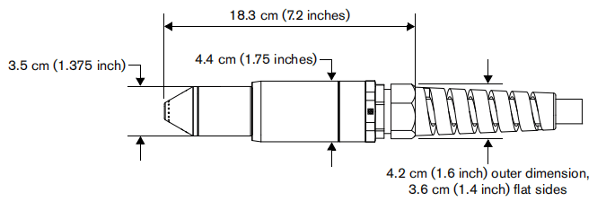
Power supply dimensions
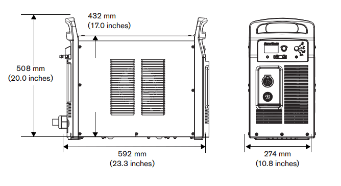
Component weights (125 A systems)
Table 1 – Power supply weights
| Voltage | 480 V CSA | 600 V CSA | 400 V CE | 380 V CCC (no power cord) |
| Power supply | 41 kg (90 pounds) | 40 kg (89 pounds) | 42 kg (92 pounds) | 38 kg (84 pounds) |
| With 7.6 m (25 foot) hand torch and 7.6 m (25 foot) work lead | 48 kg (106 pounds) | 48 kg (105 pounds) | 49 kg (108 pounds) | 45 kg (100 pounds) |
Table 2 – Torch weights
| Hand torch 7. 6 m (25 feet) | 3.5 kg ( 7.7 pounds) |
| Hand torch 15 m (50 feet) | 6.2 kg (13.7 pounds) |
| Hand torch 23 m (75 feet) | 8.8 kg (19.5 pounds) |
| Machine torch 7.6 m (25 feet) | 3.7 kg (8.2 pounds) |
| Machine torch 11 m (35 feet) | 4.8 kg (10.6 pounds) |
| Machine torch 15 m (50 feet) | 6.4 kg (14.2 pounds) |
| Machine torch 23 m (75 feet) | 9.2 kg (20.3 pounds) |
Table 3 – Work lead weights
| Work lead 7.6 m (25 feet) | 3.6 kg (8 pounds) |
| Work lead 15 m (50 feet) | 6.6 kg (14.6 pounds) |
| Work lead 23 m (75 feet) | 9.6 kg (21.2 pounds) |
Hypertherm power supply ratings
| Rated open-circuit voltage (U0) | 480/600 V CSA 400 V CE 380 V CCC | 320 VDC 305 VDC 290 VDC |
| Output characteristic1 | Drooping | |
| Rated output current (I2) | 30 – 125 A | |
| Rated output voltage (U2) | 175 VDC | |
| Duty cycle at 40° C (104° F) | 480/600 V CSA 400 V CE 380 V CCC | 100% at 125 A, 480/600 V, 3-PH 100% at 125 A, 400 V, 3-PH 100% at 125 A, 380 V, 3-PH |
| Operating temperature | ‘-10° to 40° C (14° to 104° F) | |
| Storage temperature | ’-25° to 55° C (-13° to 131° F) | |
| Power factor | 0.94 | |
| Rsce – Short Circuit Ratio (CE models only) | U1 – Volts AC rms, 3-PH | Rsce |
| 400 V CE | 250 | |
| EMC emissions classification CISPR 11 (CE models only)2 | Class A | |
| Input voltage (U1)/ Input current (I1) at rated output (U2 MAX I2 MAX) (See Power Supply Setup on page 27.) | 480/600 V CSA | 480/600 V, 3-PH, 50/60 Hz, 31/24 A |
| 400 V CE3,4 | 400 V, 3-PH, 50/60 Hz, 36 A | |
| 380 V CC | 380 V, 3-PH, 50/60 Hz, 38 A | |
| Gas type | Air | Nitrogen |
| Gas quality | Clean, dry, oil-free per ISO 8573-1 Class 1.2.2 | 99.95% pure |
| Recommended gas inlet flow rate/pressure | Cutting: 260 slpm (550 scfh, 9.2 scfm) at: • 5.9 bar (85 psi) for 7.6 m (25 foot) and 15 m (50 foot) torches • 6.6 bar (95 psi) for 23 m (75 foot) torches Gouging: 212 slpm (450 scfh, 7. 5 scfm) at 4.1 bar (60 psi) | |
1 Defined as a plot of output voltage versus output current.
2 This Class A equipment is not intended for use in residential locations where the electrical power is provided by the public low-voltage supply system. There may be potential difficulties in ensuring electromagnetic compatibility in those locations due to conducted or radiated disturbances.
3 This product meets the technical requirements of IEC 61000-3-3 and is not subject to conditional connection.
4 Equipment complies with IEC 61000-3-12 provided that the short-circuit power Ssc is greater than or equal to 5363 KVA at the interface point between the user’s supply and the public system.
It is the responsibility of the installer or user of the equipment to ensure, by consultation with the distribution network operator if necessary, that the equipment is connected only to a supply with a short-circuit power Ssc greater than or equal to 5363 KVA.
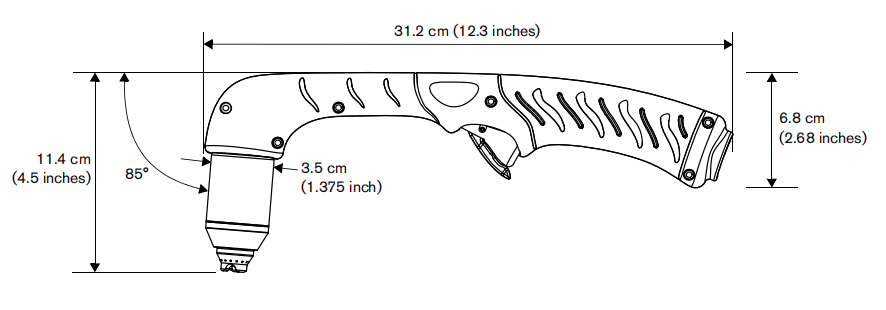
Duramax Hyamp 85° hand torch dimensions
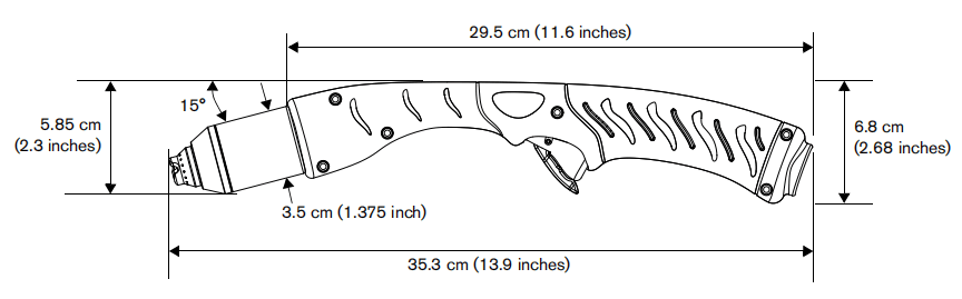
Duramax Hyamp 15° hand torch dimensions
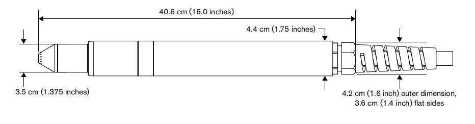
Duramax Hyamp 180° full-length machine torch dimensions
Duramax Hyamp 180° mini machine torch dimensions
Powermax125 cutting specifications
| Handheld cut capacity (material thickness) | |
| Recommended cut capacity at 457 mm/min (18 ipm)1 | 38 mm (1-1/2 inches) |
| Recommended cut capacity at 250 mm/min ( 10 ipm)1 | 44 mm (1-3/4 inches) |
| Severance capacity at 125 mm/min (5 ipm)1 | 57 mm (2-1/4 inches) |
| Pierce capacity (material thickness) | |
| Pierce capacity for handheld cutting, or mechanized cutting with programmable torch height control | 25 mm (1 inch) |
| Pierce capacity for mechanized cutting without programmable torch height control | 22 mm (7/8 inch) |
| Maximum cut speed2 (mild steel) | |
| 6 mm (1/4 inch) | 7160 mm/min (282 ipm) |
| 10 mm (3/8 inch) | 4390 mm/min (173 ipm) |
| 12 mm (1/2 inch) | 2950 mm/min (116 ipm) |
| 16 mm (5/8 inch) | 2110 mm/min (83 ipm) |
| 20 mm (3/4 inch) | 1470 mm/min (58 ipm) |
| 22 mm (7/8 inch) | 1170 mm/min (46 ipm) |
| 25 mm (1 inch) | 940 mm/min (37 ipm) |
| 32 mm (1-1/4 inches) | 6 10 mm/min (24 ipm) |
| 38 mm (1-1/2 inches) | 457 mm/min (18 ipm) |
| Gouging capacity | |
| Metal removal rate on mild steel (125 A) | 12.5 kg/hour (27 pounds/hour) |
| Duramax Hyamp series torch weights (refer to Component weights (125 A systems) on page 19) | |
| Duty cycle and voltage information (refer to Hypertherm power supply ratings on page 20) | |
1 Cut capacity speeds are not necessarily maximum speeds. They are the speeds that must be achieved to be rated at that thickness.
2 Maximum cut speeds are the results of Hypertherm’s laboratory testing. Actual cutting speeds may vary based on different cutting applications.
Symbols and markings
Your Hypertherm product may have one or more of the following markings on or near the data plate.
Due to differences and conflicts in national regulations, not all marks are applied to every version of a product.

S mark
The S mark indicates that the power supply and torch are suitable for operations carried out in environments with increased hazard of electrical shock according to IEC 60974-1.

CSA mark
Hypertherm products with a CSA mark meet the United States and Canadian regulations for product safety. The products were evaluated, tested, and certified by CSA-International.
Alternatively, the product may have a mark by one of the other Nationally Recognized Testing Laboratories (NRTL) accredited in both the United States and Canada, such as Underwriters Laboratories, Incorporated (UL) or TÜV.

CE mark
The CE marking signifies the manufacturer’s declaration of conformity to applicable European directivesand standards. Only those versions of Hypertherm products with a CE marking located on or near thedata plate have been tested for compliance with the European Low Voltage Directive and the EuropeanElectromagnetic Compatibility (EMC) Directive. EMC filters needed to comply with the EuropeanEMC Directive are incorporated within versions of the product with a CE marking.

Eurasian Customs Union (CU) mark
CE versions of Hypertherm products that include an EAC mark of conformity meet the product safety and EMC requirements for export to Russia, Belarus, and Kazakhstan.

GOST-TR mark
CE versions of Hypertherm products that include a GOST-TR mark of conformity meet the product safety and EMC requirements for export to the Russian Federation.

C-Tick mark
CE versions of Hypertherm products with a C-Tick mark comply with the EMC regulations required forsale in Australia and New Zealand.

CCC mark
The China Compulsory Certification (CCC) mark indicates that the product has been tested and foundcompliant with product safety regulations required for sale in China.

UkrSEPRO mark
The CE versions of Hypertherm products that include a UkrSEPRO mark of conformity meet the product safety and EMC requirements for export to the Ukraine.

Serbian AAA mark
CE versions of Hypertherm products that include a AAA Serbian mark meet the product safety and EMC requirements for export to Serbia.
Noise levels
This plasma system may exceed acceptable noise levels as defined by national and local codes. Always wear proper ear protection when cutting or gouging. Any noise measurements taken depend on the specific environment in which the system is used. Refer to Noise can damage hearing in the Safety and Compliance Manual (80669C) included with yoursystem.
IEC symbols
The following symbols may appear on the power supply data plate, control labels, switches, LEDs, and LCD screen.

Direct current (DC)

Alternating current (AC)

Plasma torch cutting

Plate metal cutting

Expanded metal cutting

Gouging

AC input power connection

The terminal for the external protective (earth) conductor

Power is ON

Power is OFF
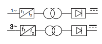
An inverter-based power source, either 1-phase or 3-phase

Volt/amperage curve, “drooping” characteristic

Power is ON (LED) AC

System fault (LED)

Inlet gas pressure fault (LCD)

Missing or loose consumables (LCD)

Power supply is out of temperature range (LCD)
Section 2 Power Supply Setup
Unpack the Powermax system
- Verify that all items on your order have been received in good condition. Contact your distributor if any parts are damaged or missing.
- Inspect the power supply for damage that may have occurred during shipping. If there is evidence of damage, refer to Claims. All communications regarding this equipment must include the model number and the serial number located on the back of the power supply.
- Beforeyou set up and operate this Hypertherm system, read the separate Safety and Compliance Manual (80669C) included with your system for important safety information.
Claims
■ Claims for damage during shipment – If your unit was damaged during shipment, you must file a claim with the carrier. Hypertherm will furnish you with a copy of the bill of lading upon request. If you need additional assistance, call the nearest Hypertherm office listed in the front of this manual.
■ Claims for defective or missing merchandise – If any component is missing or defective, contact your Hypertherm distributor. If you need additional assistance, call the nearest Hypertherm office listed in the front of this manual.
Contents
The following illustration shows typical system components. A vinyl cap is installed on torches that ship with new systems. Consumables are included in the consumable kit, and the small consumables box next to the air filter contains spare electrodes and nozzles.
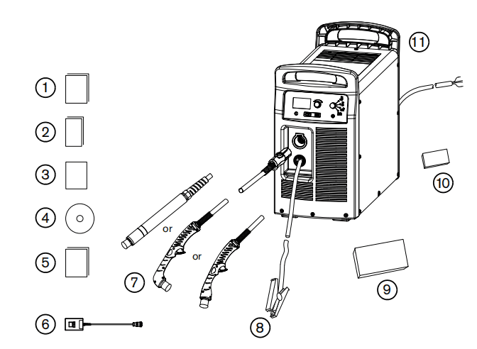
1 Operator Manual
2 Quick Setup Card
3 Registration card
4 Setup DVD
5 Safety and Compliance Manual
6 Remote-Start Pendant(optional)
7 Torches
8 Ground Clamp and Work Lead
9 Starter and Comsumable kit
10 Box with extra consumables(located next to air filter)
11 Power supply
Position the Power Supply
Locate the power supply near an appropriate power receptacle for your installation:
■480V(3-phase, CSA certified)
■600V(3-phase, CSA certified)
■400V(3-phase, CE certified)
■380V(3-phase, CCC certified)
CSA and CE certified power supplies include a 3m(10 foot) power cord(depending on the model). CCC certified power supplies do not ship with a power cord.
Allow at least 0.25 m (10 inches) of space around the power supply for proper ventilation.
The power supply is not suitable for use in rain or snow.
To avoid toppling, do not set the power supply on an incline greater than 10 degrees.
Prepare the electrical power
Hypertherm (designated HYP on the data plate) input current ratings are used to determine conductor sizes for powerconnection and installation instructions. The HYP rating is determined under maximum normal operating conditions, andthe higher HYP input current value should be used for installation purposes.

The maximum output voltage will vary based on your input voltage and the circuit’s amperage. Because the current draw varies during startup, slow-blow fuses are recommended as shown in Power connection for the Powermax125 onpage 30. Slow-blow fuses can withstand currents up to ten times the rated value for short periods of time.
Install a line-disconnect switch
Use a line-disconnect switch for each power supply so that the operator can turn off the incoming power quickly in anemergency. Locate the switch so that it is easily accessible to the operator. Installation must be performed by a licensedelectrician according to national and local codes. The interrupt level of the switch must equal or exceed the continuous rating of the fuses. In addition, the switch should:
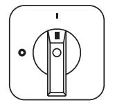
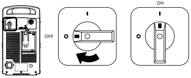
■ Isolate the electrical equipment and disconnect all live conductors from the incoming supply voltage when in the OFF position.
■ Have one OFF and one ON position that are clearly marked with O (OFF) and I (ON).
■ Have an external operating handle that can be locked in the OFF position.
■ Contain a power-operated mechanism that serves as an emergency stop.
■ Have appropriate slow-blow fuses installed. See Power connection for the Powermax125 on page 30 for recommended fuse sizes.
Requirements for grounding
To ensure personal safety, proper operation, and to reduce electromagnetic interference (EMI), the power supply must be properly grounded.
■ The power supply must be grounded through the power cord according to national and local electrical codes.
■ Three-phase service must be of the 4-wire type with a green or green/yellow wire for protective earth ground and
must comply with national and local requirements.
■ Refer to the separate Safety and Compliance Manual included with your system for more information on grounding.
Power connection for the Powermax125
Powermax125 3-phase systems are available in the following fixed-voltage configurations:
■ 480 V CSA
■ 600 V CSA
■ 400 V CE
■ 380 V CCC
The Hypertherm rated output is 30 – 125 A, 175 VDC.
Table 4 – 480 V CSA
| Input voltage (V) | 480 |
| Input current (A) at rated output (21.9 kW) | 31 |
| Input current (A) at arc stretch | 50 |
| Fuse, slow-blow (A) | 50 |
Table 5 – 600 V CSA
| Input voltage (V) | 600 |
| Input current (A) at rated output (21.9 kW) | 24 |
| Input current (A) at arc stretch | 38 |
| Fuse, slow-blow (A) | 40 |
Table 6 – 400 V CE
| Input voltage (V) | 400 |
| Input current (A) at rated output (21.9 kW) | 36 |
| Input current (A) at arc stretch | 55 |
| Fuse, slow-blow (A) | 60 |
Table 7 – 380 V CCC
| Input voltage (V) | 380 |
| Input current (A) at rated output (21.9 kW) | 38 |
| Input current (A) at arc stretch | 55 |
| Fuse, slow-blow (A) | 60 |
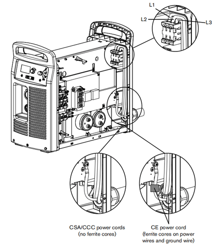
Three-phase power cord and plug installation
Powermax125 power supplies ship with the following power cords:
■ CSA models: 8 AWG 4-wire power cord (no power plug included)
■ CE models: 10 mm2 4-wire HAR power cord (no power plug included)
CCC certified configurations do not ship with a power cord.
If you need to install a different power cord on the system, the cable you use must have a diameter within one of the following ranges to ensure a proper fit in the power cord strain relief:
■ CSA and CCC models: 15.0 – 25.4 mm (0.59 – 1.00 inches)
■ CE models: 20.0 – 25.9 mm (0.79 – 1.02 inches)
To operate the Powermax, use a plug that meets national and local electrical codes. The plug must be connected to the power cord by a licensed electrician.
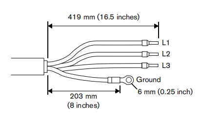
Strip and prepare the power cord wires as shown in the following figure. For CE units, ferrite cores are installed around the three power wires and around the ground wire; CSA and CCC models do not have ferrite cores on the power cordwires.

Extension cord recommendations
Any extension cord must have an appropriate wire size for the cord length and system voltage. Use a cord that meetsnational and local codes.
For all Powermax125 configurations, the recommended gauge size for any three-phase extension cord between3 – 45 m ( 10 – 150 feet) is 10 mm2 (8 AWG).
Engine-driven generator recommendations
Generators used with the Powermax125 should satisfy the voltage requirements in the following table and in Hypertherm power supply ratings on page 20.
| Engine drive rating | System output current | Performance (arc stretch) |
| 40 kW | 125 A | Full |
| 30 kW | 125 A | Limited |
| 30 kW | 100 A | Full |
| 25 kW | 100 A | Limited |
| 22.5 kW | 75 A | Full |
| 20 kW | 75 A | Limited |
| 20 kW | 60 A | Full |
| 15 kW | 60 A | Limited |
| 12 kW | 40 A | Full |
| 10 kW | 40 A | Limited |
| 10 kW | 30 A | Full |
| 8 kW | 30 A | Limited |
Based on the generator rating, age, and condition, adjust the cutting current as needed.
If a fault occurs while using a generator, turning the power switch quickly to OFF and then to ON again (sometimes called a “quick reset”) may not clear the fault.
Instead, turn OFF the power supply and wait 60 to 70 seconds before turning it ON again.
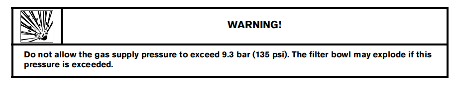
Prepare the gas supply
The air can be supplied by a compressor or from high-pressure cylinders. A high-pressure regulator must be used oneither type of supply and must be capable of delivering gas to the air inlet on the power supply.

The system contains a built-in filter element, but additional filtration may be required depending on the quality of the gas supply.
If the supply quality is poor, cut speeds decrease, cut quality deteriorates, cutting thickness capability decreases, and the life of the consumables shortens. For optimal performance, the gas should be compliant with ISO8573-1:2010, Class 1.2.2 (that is, it should have a maximum number of solid particulate per meter cubed of 20,000 for particle sizes in the range of 0.1 – 0.5 microns, a maximum of 400 for particle sizes in the range of 0.5 – 1 microns, and a maximum of 10for particle sizes in the range of 1 – 5 microns). The maximum water vapor dew point should be -40° C (-40° F). Themaximum oil (aerosol, liquid, and vapor) content should be 0.1 mg/m3.
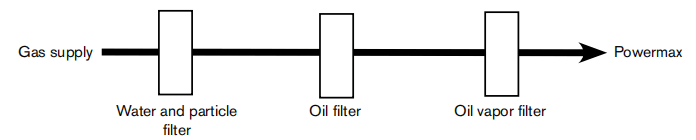
Additional gas filtration
When site conditions introduce moisture, oil, or other contaminants into the gas line, use a 3-stage coalescing filtration system, such as the Eliminizer filter kit (228890) available from Hypertherm distributors. A 3-stage filtering system works as follows to clean contaminants from the gas supply.
Connect the gas supply
Connect the gas supply to the power supply using an inert-gas hose with a 9.5 mm (3/8 inch) internal diameter and a1/4 NPT quick-disconnect coupler (CSA units) or a 1/4 NPT x G-1/4 BSPP (CE/CCC units) quick-disconnect coupler.

Minimum inlet pressure (while gas is flowing)
This table shows the minimum required inlet pressure when the recommended inlet pressure is not available.
| Torch lead length | 7.6 m (25 feet) | 15.2 m (50 feet) | 22.9 m (75 feet) |
| Process | Minimum inlet pressure | ||
| Cutting | 5.9 bar (85 psi) | 5.9 bar (85 psi) | 6.6 bar (95 psi) |
| Gouging | 4.1 bar (60 psi) | 4.1 bar (60 psi) | 4.1 bar (60 psi) |
Gas flow rates
| Process | Gas flow rate | ||
| Cutting | 260 slpm (550 scfh, 9.2 scfm) at a minimum: • 5.9 bar (85 psi) for 7.6 m (25 foot) and 15 m (50 foot) torches • 6.6 bar (95 psi) for 23 m (75 foot) torches | ||
| Gouging | 212 slpm (450 scfh, 7.5 scfm) at a minimum 4.1 bar (60 psi) | ||
Section 3 Basic System Operations
Controls and indicators
Powermax power supplies have the following controls and indicators: ON/OFF switch, adjustment knob,automatic/manual pressure setting mode selector, current/gas selector, operating mode switch, indicator LEDs, and a status screen. These controls and indicators are described on the following pages.
Rear controls
ON (I)/OFF (O) power switch – Activates the power supply and its control circuits.
Front controls and LEDs
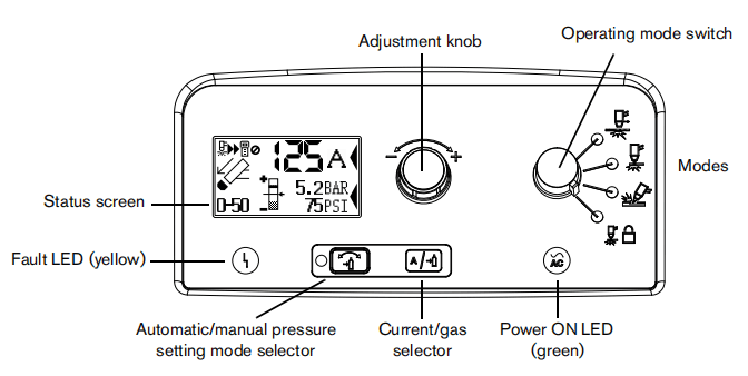
LEDs

Power ON LED (green) – When illuminated, this LED indicates that the power switch has been set to
I (ON) and that the safety interlocks are satisfied. When blinking, the power supply has a fault.

Fault LED (yellow) – When illuminated, this LED indicates that there is a fault with the power supply.
Selectors
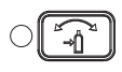
Automatic/manual pressure setting mode selector – The selector switches between automatic and manual mode. In automatic mode, the power supply automatically sets the gaspressure based on the torch type and lead length, and the adjustment knob sets only theamperage. In manual mode, the adjustment knob sets either the gas pressure or the amperage. This LED is illuminated in manual mode.
Manual mode should be used by experienced users who need to optimize the gas setting (override the automatic gas setting) for a specific cutting application.
When you switch from manual mode to automatic mode, the power supply automatically sets the gas pressure, and the amperage setting is unchanged.
When you switch from automatic mode to manual mode, the power supply remembers the previous manual gas pressure setting, and theamperage setting is unchanged.
When you reset the power, the power supply remembers the previous mode, gas pressure, and amperage settings.

Current/gas selector – When in manual mode, this selector toggles between amperage and gas pressure for manual adjustments using the adjustment knob.
Operating mode switch
For more information on these modes, see Set the operating mode switch on page 45.

The operating mode switch can be set in one of four positions:
■ Continuous pilot arc. Cuts expanded metal or grate.
■ Non-continuous pilot arc. Cuts or pierces metal plate. This is the standard setting for normal drag- cutting.
■ Gouge. Gouges metal plate.
■ Torch lock. Same as the non-continuous pilot arc mode except the torch is locked in the ON position when you release the trigger during a cut. The torch goes out when the transfer is lost or the torch is retriggered.
Amperage adjustment knob
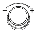
This knob adjusts the amperage. When operating in manual mode, you can also use this knob to adjust the gas pressure, overriding the automatic setting for optimized applications.
Status screen

1 Torch is cutting
2 Torch start
3 Fault icon
4 Fault code
5 Visual pressure setting
6 Pressure setting
7 Pressure selection cursor
8 Current selection cursor
9 Current setting (amperage)
10 Electrode end of life detection manually disabled
11 Remote connected
Gas pressure indicators
In manual mode, the gas pressure is displayed in measurements of bar and psi. The gas pressure bar is also a visual indicator of the gas pressure.

Gas pressure bar – When the arrow is centered in the vertical bar (the reference pressure of the automatic pressure setting), the gas pressure is set to the preset (factory-defined) value. If the pressure is higher than the preset value, the arrow appears above the mid-point of the bar. If the pressure is lowerthan the preset value, the arrow appears below the mid-point of the bar.
In automatic mode, the power supply adjusts the pressure to the preset value.
You can use manual mode to adjust the pressure to satisfy the needs of a particular cutting job. See Manually adjusting the gas pressure on page 46.
System status icons
The screen displays icons to indicate the system’s status.

Torch started – Indicates that the torch has received a start signal.

Torch is cutting – Indicates that the cutting arc has transferred to the metal, and the torch is cutting.

Remote control – Indicates that a remote control or CNC is controlling the power supply using serial communications. All local controls are disabled.

Electrode end-of-life detection manually disabled – Indicates that the electrode end-of-life detection feature is manually disabled.
Fault codes and icons
When a power supply or torch fault occurs, the system displays a fault code in the lower-left corner of the status screen and displays a corresponding fault icon above the code.

Fault code – The first digit is always zero. The other two digits identify the problem. Fault code
information is included later in this manual.
Only one fault code is displayed. If more than one fault occurs at the same time, only the fault code with the highest priority is displayed.
Fault icon – The fault icons that appear on the left side of the status screen are described below.
A fault code also appears to identify the fault.
Refer to the troubleshooting information later in this manual.

Warning – The system continues to run.

Fault – The system stops cutting. If you cannot correct the problem and restart the system, contact your distributor or Hypertherm Technical Service.

Error – The system requires service. Contact your distributor or Hypertherm Technical Service.

Torch cap sensor – Indicates that the consumables are loose, improperly installed, or missing.
Turn OFF the power, properly install the consumables, and turn ON the system again to reset thepower supply.

Temperature – Indicates that the temperature of the power supply power module is outside the acceptable operating range.

Gas – Indicates that the gas is disconnected from the rear of the power supply or there is a problem with the gas supply.

Internal Serial Communications Interface – Indicates a problem with communications
between the control board and the DSP board.
Operating the Powermax
Follow the steps below to begin cutting or gouging with the system.
This section provides basic operating instructions. Before operating your system in a production environment, refer to Hand Torch Setup on page 49 or Machine Torch Setup on page 65.
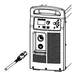
Connect the electrical power, gas supply, and torch lead
For information on connecting the proper plug to the power cord, refer to Power Supply Setup on page 27.
Plug in the power cord and connect the gas supply line. For more information about the electrical requirements and the gas supply requirements of the Powermax, see Power Supply Setup on page 27. To connect the torch, push the FastConnect connector into the receptacle on the front of the power supply.
You will attach the work lead in the next step.
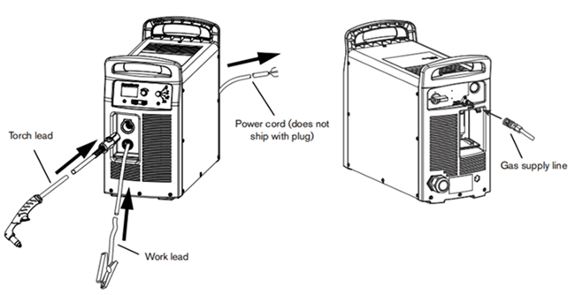
CCC units do not ship with a power cord.
Attach the work lead to the power supply
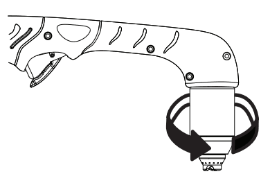
1.Insert the work lead connector into the receptacle on the front of the power supply.The receptacle is keyed. Align the key on the work lead connector with the opening at thetop of the receptacle on the power supply.

- Push thework lead connector all the way into the receptacle on the power supply and turn clockwise, approximately 1/4 turn, until the connector is fully seated against the stop in order to achieve an optimal electrical connection. A loose connection will overheat the connector. Frequently check the work lead for a reliable electrical connection.

Attach the ground clamp to the workpiece
The ground clamp must be connected to the workpiece while you are cutting. If you are using the Powermax with acutting table, you can connect the work lead directly to the table instead of attaching the ground clamp to the workpiece.See your table manufacturer’s instructions.
Make sure that the ground clamp and the workpiece make good metal-to-metal contact.
Remove rust, dirt, paint, coatings, and other debris to ensure the work lead makes proper contact with the workpiece.
For the best cut quality, attach the ground clamp as close as possible to the area being cut.


Turn on the system
Set the ON/OFF switch to the ON (I) position.
Set the operating mode switch
Use the operating mode switch to select the type of work you want to perform.
In automatic gas mode, Smart Sense technology automatically adjusts the gas pressure according to the selected cutting mode and torch lead length for optimum cutting.

For cutting expanded metal, grates, metal containing holes, or any job thatrequires a continuous pilot arc. Using this mode to cut standard metal platereduces consumable life.
For cutting or piercing metal. This is the standard setting for normal drag-cutting.
For gouging metal.
Using this mode while cutting results in poor cut quality.
For locking the torch in the ON (fire) position. With this option selected, press the trigger to fire the torch. The trigger will remain on when you release the trigger.The arc will go out when transfer is lost or you press the trigger again.
Check the indicators
Verify the following:
■ The green power ON LED on the front of the power supply is illuminated.
■ The Fault LED is not illuminated.
■ No error icons appear in the status screen.
If a fault icon appears in the status screen, or the Fault LED is illuminated, or the power ON LED is blinking, correct thefault condition before continuing.
More troubleshooting information is included later in this manual.
Manually adjusting the gas pressure
For normal operations, the power supply automatically adjusts the gas pressure. If you need to adjust the gas pressure for a specific application, you can use manual mode to do so.
Manual mode should be used by experienced users who need to optimize the gas setting (override the automatic gas setting) for a specific cutting application.
When you switch from manual mode to automatic mode, the power supply automatically sets the gas pressure, and theamperage setting is unchanged.
When you switch from automatic mode to manual mode, the power supply remembers the previous manual gas pressure setting, and the amperage setting is unchanged.
When you reset the power, the power supply remembers the previous mode, gas pressure, and amperage settings.
To adjust the pressure:
1. Press the automatic/manual pressure setting mode selector so that the LED next to the selector illuminates. Refer to Front controls and LEDs on page 38.
2. Press the current/gas selector until the selection cursor is opposite the gas pressure setting in the status screen.
3. Turn the adjustment knob to adjust the gas pressure to the desired level. Watch the arrow in the pressure bar as you adjust the pressure. (See Gas pressure indicators on page 40.)
Adjusting the current (amperage)
Turn the adjustment knob to adjust the current for your particular cutting application.
If the system is in manual mode, do the following to adjust the amperage:
1. Press the current/gas selector until the selection cursor is opposite the amperage setting in the status screen.
2. Turn the adjustment knob to change the amperage.
3. If you wish to exit manual mode, press the automatic/manual pressure setting mode selector. The LED goes off.
When you exit manual mode, the gas pressure resets to the factory-optimized value.
When you switch between manual mode and automatic mode, the power supply retains the amperage setting. When you reset the power, the power supply returns to the previous mode (automatic mode or manual mode) and remembers the previous amperage setting.
Electrode end-of-life detection feature
The electrode end-of-life detection feature on the system protects the torch and workpiece from damage by automatically stopping power to the torch when the electrode reaches its end of life. Fault code 0-32 also displays on the front panelstatus screen.
If you have the current set below 55 A, this feature is automatically disabled without displaying the icon on the status screen.
To manually disable the feature:
1. Set the system to auto mode.
2. Press the current/gas selector button (see Figure 1) five times in quick succession, less than one second apart.
The icon (see Figure 1) displays on the status screen.
3. To re-enable the feature, press the current/gas selector button five times again in quick succession, less than one second apart.
The icon disappears.

Understanding duty-cycle limitations
The duty cycle is a percentage of time out of 10 minutes that a plasma arc will remain on when operating at an ambient temperature of 40° C (104° F). For example, if the system runs for 6 minutes before overheating and cools off enough to produce an arc in less than 4 minutes, it has a 60% duty cycle.
If the power supply overheats, the temperature fault icon appears in the status screen, the arc shuts off, and the cooling fan continues to run. Yo u cannot resume cutting until the temperature fault icon disappears and the fault LED goes off.
The fan may run during normal operation of the system.
With a Powermax125:
■ At 125 A (480/600 V CSA, 400 V CE, 380 V CCC), the arc can remain on for 10 minutes out of 10 minutes without causing the unit to overheat (100% duty cycle).
Section 4 Hand Torch Setup
Introduction
Duramax Hyamp series hand torches are available for Powermax125 systems. The FastConnect quick-disconnect system makes it easy to remove the torch for transport or to switch from one torch to the other if your applications require the use of different torches. The torches are cooled by ambient air and do not require special cooling procedures.
This section explains how to set up your hand torch and choose the appropriate consumables for the job.
Consumable life
How often you need to change the consumables on your torch will depend on a number of factors:
■ The thickness of the metal being cut.
■ The average length of the cut.
■ The air quality (presence of oil, moisture, or other contaminants).
■ Whether you are piercing the metal or starting cuts from the edge.
■ Proper torch-to-work distance when gouging.
■ Proper pierce height.
■ Whether you are cutting in “continuous pilot arc” mode or normal mode. Cutting with a continuous pilot arc causes more consumable wear.
Under normal conditions, the nozzle will wear out first when hand cutting. As general rule, a set of consumables lasts approximately 1 to 3 hours of actual “arc on” time for 125 A hand cutting. Cutting at lower amperages may yield longer consumable life.
Yo u will find more information about proper cutting techniques in Hand Cutting on page 55.
Hand torch components
The hand torches ship without consumables installed.
Duramax Hyamp 85° hand torch
Duramax Hyamp 15° hand torch
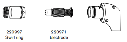
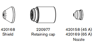
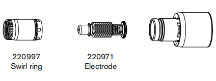
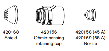
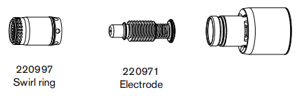
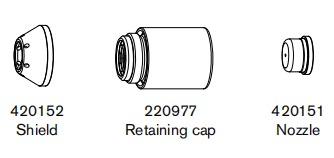
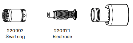
Choose the hand torch consumables
Hypertherm includes a starter consumable kit and a box of spare electrodes and nozzles with your system. Both styles ofhand torches shown above use the same consumables.
Hand torches use shielded consumables. Therefore, you can drag the torch tip along the metal.
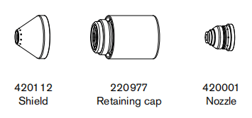
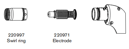
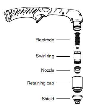
Consumables for hand cutting are shown below. Notice that the retaining cap and electrode are the same for cutting,gouging, and FineCut® applications. Only the shield, nozzle, and swirl ring are different.
For the best cut quality on thin materials (approximately 4 mm/10 GA or less), you may prefer to use FineCutconsumables, or use a 45 A nozzle and reduce the amperage to that setting.
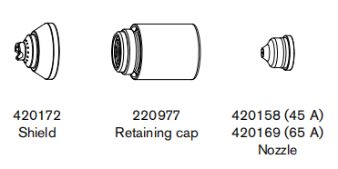
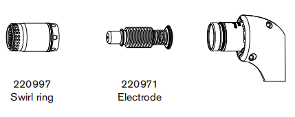
Drag-cutting 105/125 A consumables
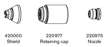
Drag-cutting 45 A and 65 A consumables
Gouging consumables
FineCut consumables

Install the hand torch consumables
To operate the hand torch, a complete set of consumable parts must be installed: shield, retaining cap, nozzle, electrode,and swirl ring. Torches ship without consumables installed. Pull off the vinyl cap before installing your consumables.
With the power switch in the OFF (O) position, install the Powermax125 torch consumables as shown.
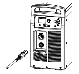
Connecting the torch lead
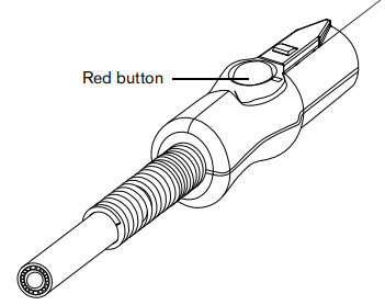
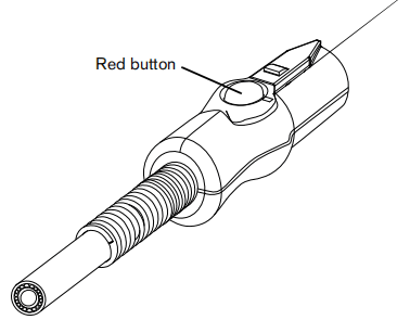
The system is equipped with FastConnect, a quick-disconnect system for connecting and disconnecting handheld and machine torch lead. When connecting or disconnecting a torch, first turn OFF the system. To connect the torch, push the connector into the receptacle on the front of the power supply.
To remove the torch, press the red button on the connector out of the receptacle.
Section 5 Hand Cutting
Using the hand torch

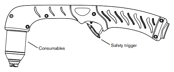
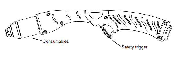
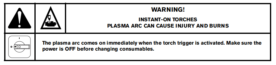
Operate the safety trigger
The hand torches are equipped with a safety trigger to prevent accidental firings. When you are ready to use the torch,flip the trigger’s safety cover forward (toward the torch head) and press the red torch trigger.

Hand torch cutting guidelines
■ Drag the torch tip lightly along the workpiece to maintain a steady cut.
■ While cutting, make sure that sparks exit from the bottom of the workpiece. The sparks should lag slightly behind the torch as you cut (15 – 30° angle from vertical).
■ If sparks spray up from the workpiece, move the torch more slowly, or set the output current higher.
■ With either hand torch, hold the torch nozzle perpendicular to the workpiece so that the nozzle is at a 90° angle to the cutting surface. Observe the cutting arc as the torch cuts.

■ If you fire the torch unnecessarily, you will shorten the life of the nozzle and electrode.

■ Pulling, or dragging, the torch along the cut is easier than pushing it.
■ For straight-line cuts, use a straight edge as a guide. To cut circles, use a template or a radius cutter attachment (a circle cutting guide).
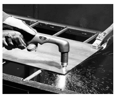
Start a cut from the edge of the workpiece

- With the ground clamp attached to the workpiece, hold the torch nozzle perpendicular (90°) to the edge of the workpiece.

- Press the torch’strigger to start the arc. Pause at the edge until the arc has cut completely through the workpiece.

- Drag the torch tip lightly across the workpiece to proceed with the cut. Maintain a steady, even pace.
Pierce a workpiece

- With the ground clamp attached to the workpiece, hold the torch at an approximate 30° angle to the workpiece with the torch tip within 1.5 mm (1/16 inch) of the workpiece before firing the torch.

- Fire the torch while still at an angle to the workpiece. Slowly rotate the torch to a perpendicular (90°) position.
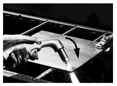
- Hold the torchin place while continuing to press the trigger. When sparks exit below the workpiece, the arc has pierced the material.
- When the pierce is complete, drag the nozzle lightly along the workpiece to proceed with the cut.
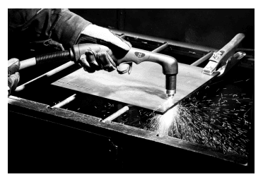
Gouge a workpiece


- Hold the torch so that the torch tip is slightly above the workpiece before firing the torch.
- Hold the torch at a 30 – 45° angle to the workpiece, with a small gap between the torch tip and the workpiece. Press the trigger to obtain a pilot arc. Transfer the arc to the workpiece.
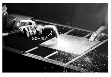
- Change the torch’s angle as needed to achieve the desired dimensions for the gouge. Refer to Varying the gouge profile on page 62 and 125 A gouging profile chart on page 62.
- Maintain the same angle to the workpiece as you feed into the gouge. Push the plasma arc in the direction of the gouge you want to create. Keep a small distance between the torch tip and the molten metal to avoid reducing consumable life or damaging the torch.

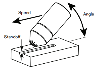
Gouge profile
Yo u can vary the gouge profile by varying the:
■ Speed of the torch over the workpiece
■ Torch-to-work standoff distance
■ Angle of the torch to the workpiece
■ Current output of the power supply
| Operating parameters | |
| Speed | 508 – 1270 mm/min (20 – 50 ipm) |
| Standoff | 6.4 – 10.2 mm (1/4 – 2/5 inch) |
| Angle | 30 – 35° |
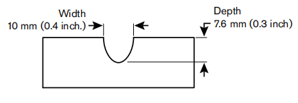
Typical gouging profile
125 A
Metal removal rate on mild steel 12.5 kg/hour (27 pounds/hour)
Varying the gouge profile
Follow these recommendations to change the gouge profile as needed:
■ Increasing the speed of the torch will decrease width and decrease depth.
■ Decreasing the speed of the torch will increase width and increase depth.
■ Increasing the standoff of the torch will increase width and decrease depth.
■ Decreasing the standoff of the torch will decrease width and increase depth.
■ Increasing the angle of the torch (more vertical) will decrease width and increase depth.
■ Decreasing the angle of the torch (less vertical) will increase width and decrease depth.
■ Increasing the current of the power supply will increase width and increase depth.
■ Decreasing the current of the power supply will decrease width and decrease depth.
125 A gouging profile chart
The following tables show the 125 A gouging profile at 30° and 35° on mild steel. These settings are intended to serve asa starting point to help you determine the best gouging profile for a given cutting job. Adjust these settings as needed foryour application and table to obtain the desired result.
Table 8 – Metric
| Torch angle | Standoff (mm) | Speed (mm/min) | Depth (mm) | Width (mm) | Width/depth ratio |
| 30° | 6.3 | 508 | 7.9 | 8.4 | 1.06 |
| 762 | 6.6 | 7.6 | 1.16 | ||
| 1016 | 5.5 | 6.6 | 1.21 | ||
| 1270 | 4.4 | 6.1 | 1.38 | ||
| 10.1 | 508 | 7.6 | 9.8 | 1.30 | |
| 762 | 6.1 | 8.7 | 1.43 | ||
| 1016 | 4.8 | 7.3 | 1.50 | ||
| 1270 | 4.2 | 7.0 | 1.66 | ||
| 35° | 6.3 | 508 | 7.5 | 6.8 | 0.92 |
| 762 | 5.7 | 6.5 | 1.13 | ||
| 1016 | 4.5 | 5.5 | 1.26 | ||
| 1270 | 4.2 | 5.2 | 1.24 | ||
| 10.1 | 508 | 7.3 | 8.1 | 1.12 | |
| 762 | 5.7 | 7.5 | 1.30 | ||
| 1016 | 5.7 | 6.4 | 1.12 | ||
| 1270 | 4.4 | 6.0 | 1.35 |
Table 9 – English
| Torch angle | Standoff (mm) | Speed (mm/min) | Depth (mm) | Width (mm) | Width/depth ratio |
| 30° | 0.25 | 20 | 0.31 | 0.33 | 1.06 |
| 30 | 0.26 | 0.30 | 1.16 | ||
| 40 | 0.22 | 0.26 | 1.21 | ||
| 50 | 0.17 | 0.24 | 1.38 | ||
| 0.4 | 20 | 0.30 | 0.39 | 1.30 | |
| 30 | 0.24 | 0.34 | 1.43 | ||
| 40 | 0.19 | 0.29 | 1.50 | ||
| 50 | 0.17 | 0.28 | 1.66 | ||
| 35° | 0.25 | 20 | 0.30 | 0.27 | 0.92 |
| 30 | 0.23 | 0.26 | 1.13 | ||
| 40 | 0.18 | 0.22 | 1.26 | ||
| 50 | 0.17 | 0.21 | 1.24 | ||
| 0.4 | 20 | 0.29 | 0.32 | 1.12 | |
| 30 | 0.23 | 0.30 | 1.30 | ||
| 40 | 0.23 | 0.25 | 1.12 | ||
| 50 | 0.18 | 0.24 | 1.35 |
Common hand-cutting faults
The torch does not cut completely through the workpiece. The causes can be:
■ The cut speed is too fast.
■ The consumables are worn.
■ The metal being cut is too thick for the selected amperage.
■ Gouging consumables are installed instead of drag-cutting consumables.
■ The ground clamp is not attached properly to the workpiece.
■ The gas pressure or gas flow rate is too low.
■ Gouging mode is selected on the power supply.
Cut quality is poor. The causes can be:
■ The metal being cut is too thick for the amperage.
■ The wrong consumables are being used (gouging consumables are installed instead of drag-cutting consumables, for example).
■ The torch is moving too quickly or too slowly.
The arc sputters and consumable life is shorter than expected. The causes can be:
■ Moisture in the gas supply.
■ Incorrect gas pressure.
■ Consumables incorrectly installed.
■ The consumables are worn.
Section 6 Machine Torch Setup
Introduction
Duramax Hyamp series machine torches are available for this system. The FastConnect quick-disconnect system makes iteasy to remove the torch for transport or to switch from one torch to the other if your applications require the use of different torches. The torches are cooled by ambient air and do not require special cooling procedures.
This section explains how to set up your machine torch and choose the appropriate consumables for the job.
Consumable life
How often you need to change the consumables on your torch will depend on a number of factors:
■ The thickness of the metal being cut.
■ The average length of the cut.
■ The air quality (presence of oil, moisture, or other contaminants).
■ Whether you are piercing the metal or starting cuts from the edge.
■ Proper torch-to-work distance when gouging.
■ Proper pierce height.
■ Whether you are cutting in “continuous pilot arc” mode or normal mode. Cutting with a continuous pilot arc causes more consumable wear.
Under normal conditions, the electrode will wear out first during machine cutting. As general rule, a set of consumables should last about 1 to 3 hours for 125 A mechanized cutting, depending on the job. Cutting at lower amperages may yield longer consumable life.
You will find more information about proper cutting techniques in Mechanized Cutting on page 97.
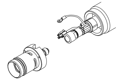
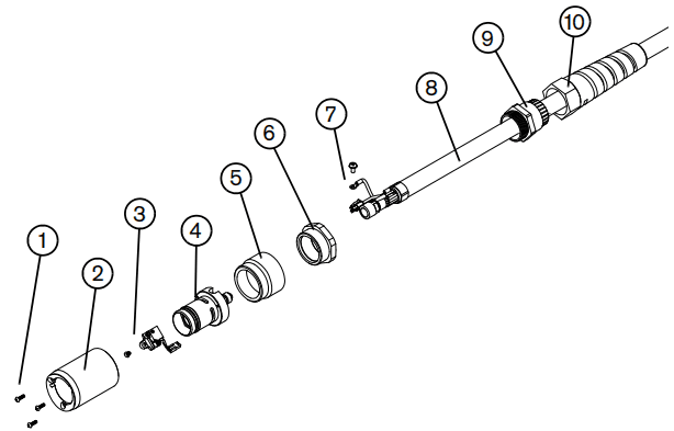
Machine torch components
Duramax Hyamp 180° machine torch
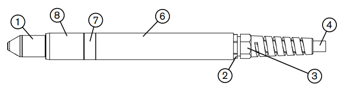
See the following callout table.
Duramax Hyamp 180° mini machine torch
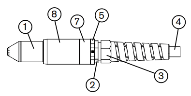
1 Consumables
2 Strain relief
3 Strain relief nut
4 Torch lead
5 Adapter (not used in the full-length machine torch)
6 Positioning sleeve (not used in the mini machine torch)
7 Coupler
8 Mounting sleeve
Before using either style of machine torch, you must:
■ Mount the torch on your cutting table or other equipment.
■ Choose and install the consumables.
■ Align the torch square to the plate.
■ Attach the torch lead to the power supply.
■ Set up the power supply for remote starting with either the remote-start pendant or a machine interface cable.
Disassemble the machine torch
You may need to disassemble the machine torch in order to mount it on a cutting table (see Mount the torch on page 70).Another reason to disassemble the machine torch is to convert it from the full-length machine torch to a mini machinetorch (see Convert a full-length machine torch to a mini machine torch on page 69).
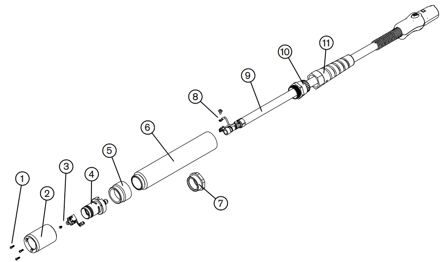
1 Mounting sleeve screws
2 Mounting sleeve
3 Cap-sensor switch and screw
4 Torch body
5 Coupler
6 Positioning sleeve (full-length machine torch only)
7 Adapter (mini machine torch only)
8 Pilot arc wire and screw
9 Torch lead
10 Strain relief
11 Strain relief nut
While disconnecting and reconnecting the torch parts, maintain the same orientation between the torch head and torch lead.
Twisting the torch head in relation to the torch lead can cause damage to the torch wires.
- Disconnect the torch lead from the power supply, and remove the consumables from the torch.
- Unscrew the strain relief nut fromthe strain relief, and slide the nut back along the torch lead.
- If you are disassembling the full-length machine torch, unscrew the strain relief from the positioning sleeve. If you are disassembling the mini machine torch, unscrew the strain relief from the adapter. Slide the strain relief back along the torch lead.
- If you are disassembling the full-length machinetorch, unscrew the positioning sleeve from the coupler. If you are disassembling the mini machine torch, unscrew the adapter from the coupler.
- Unscrew the coupler fromthe mounting sleeve.
- Remove the three screws fromthe consumables end of the mounting sleeve, and slide the mounting sleeve off the front of the torch body.
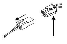
- Disconnect the wire connector for the cap-sensor switch.
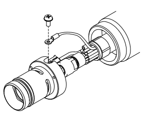
- Remove the screw that secures the torch’s pilot wire to the torch body.
- Use5/16-inch and 1/2inch wrenches,or adjustable wrenches,to loosen the nut that secures the gas supply line to the torch lead. Set the torch body aside.
- Slide the coupler off the front of thetorch lead.
- If you are disassembling a full-length machine torch, slide the positioning sleeve off the front of the torch lead. If you are disassembling a mini machine torch, slide the adapter off the front of the torch lead.
Convert a full-length machine torch to a mini machine torch
You will need the mini machine torch adapter kit (428146) to complete the following procedure. This kit enables you toconvert a full-length machine torch to a mini machine torch by removing the positioning sleeve and installing a small adapter ring in its place.
If you are converting a full-length machine torch to a mini machine torch and mounting the torch at the same time, skip this procedure and follow the instructions in Mount the torch on page 70.
1 Mounting sleeve screws
2 Mounting sleeve
3 Cap-sensor switch and screw
4 Torch body
5 Coupler
6 Adapter (428146)
7 Pilot arc wire and screw
8 Torch lead
9 Strain relief
10 Strain relief nut
1. Follow the instructions in Disassemble the machine torch on page 67.
2. Slide the adapter over the torch lead.
3. Slide the coupler over the torch lead.
4. Screw the adapter onto the coupler.
5. Reconnect the gas supply line to the torch lead.
6. Reattach the torch’s pilot wire to the torch body using the screw.
7. Reconnect the cap-sensor switch’s wire connector.
- Slide the mounting sleeve over the front of the torchbody. Align the slot on the front of the mounting sleeve (next to one of the three screw holes) with the cap-sensor plunger on the torch body.
- Attach the mounting sleeve to the torchbody using the three screws.
- Screw the coupler ontothe mounting sleeve.
- Screw thestrain relief onto the adapter.
- Screw thestrain relief nut onto the strain relief.
- Reinstall the consumables in the torch,and reconnect the torch lead to the power supply.
Mount the torch
The machine torches can be mounted on a wide variety of X-Y tables, track burners, pipe bevelers, and other equipment.Install the torch per the manufacturer’s instructions. Use the following procedure to disassemble and reassemble thetorch if you need to do so in order to route the torch through the cutting table’s track or other mounting system.
If your cutting table’s track is large enough for you to route the torch through it without removing the torch body from thelead, do so and then attach the torch to the lifter per the manufacturer’s instructions.
While disconnecting and reconnecting the torch parts, maintain the same orientation between the torch head and torch lead.
Twisting the torch head in relation to the torch lead can cause damage to the torch wires.
- Follow the instructions in Disassemble the machine torch on page 67.
Cover the end of the gas line on the torch lead with tape to keep dirt and other contaminants from getting in the gas line when you route the lead through the track.
- Route the torchlead through the mounting system for the cutting table. Slide the strain relief and strain relief nut along the torch lead as needed to move them out of the way as you route the torch lead through the track.
- If you are mounting a full-length machine torch, slide the positioning sleeve over the torch lead. If you are mounting a mini machine torch, slide the adapter over the torch lead.
- Slide the coupler over the torchlead.
- Reconnect the gas supply line to the torchlead.
- Reattach the torch’s pilot wire to the torch body using the screw.
- Reconnect the cap-sensor switch’swire connector.
- Slide the mounting sleeve over the front of the torchbody. Align the slot on the front of the mounting sleeve (next to one of the three screw holes) with the cap-sensor plunger on the torch body.
- Attach the mounting sleeve to the torchbody using the three screws.
- Screw the coupler into the mounting sleeve.
- If you are mounting a full-lengthmachine torch, screw the positioning sleeve into the coupler. If you are mounting a mini machine torch, screw the adapter into the coupler.
- Screw the strain relief intothe positioning sleeve (for a full-length machine torch) or the adapter (for a mini machine torch).
- Screw the strain relief nut into the strain relief.
- Attach the torch to the lifter per the manufacturer’s instructions.
- Reinstall the consumables in the torch.
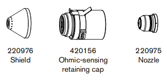
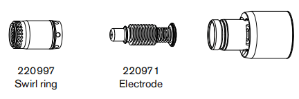
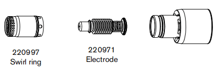
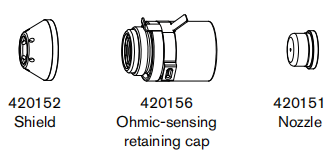
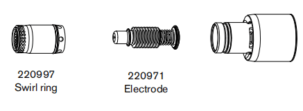
Choose the machine torch consumables
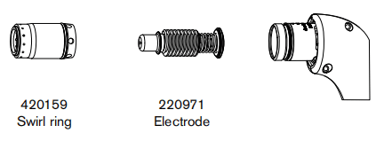
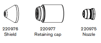
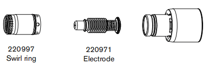
Systems with the Duramax Hyamp 180° full-length machine torch or Duramax Hyamp 180° mini machine torch ship with a starter consumable kit as well as a box of spare electrodes and nozzles. There are two starter mechanized consumable kits. One includes the standard retaining cap, and one includes the ohmic retaining cap. Notice that the retaining cap, electrode, and swirl ring are the same for cutting, gouging, and FineCut applications. Only the shield and nozzle are different.
Both styles of machine torches use the same consumables. Mechanized consumables are shielded. Therefore, if the torch touches the workpiece it will not damage the nozzle.
Machine torch consumables
Mechanized shielded 105 A/125 A consumables
Mechanized shielded 45 A and 65 A consumables
Mechanized shielded with ohmic 105 A/125 A consumables
Mechanized shielded with ohmic 45 A and 65 A consumables
Gouging consumables
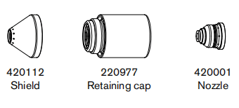
FineCut shielded consumables
FineCut shielded with ohmic consumables
Install the machine torch consumables
To operate the machine torch, a complete set of consumable parts must be installed: shield, retaining cap, nozzle,electrode, and swirl ring.
With the power switch in the OFF (O) position, install the machine torch consumables in a manner similar to the handtorch consumables. See Hand Torch Setup on page 49.
Aligning the torch
Mount the machine torch perpendicular to the workpiece in order to get a vertical cut. Use a square to align the torch atright angles to the workpiece.
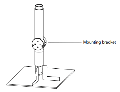
Position the mounting bracket as low on the torch as possible to minimize vibration at the tip of the torch.
Connecting the torch lead
This system is equipped with FastConnect, a quick-disconnect system for connecting and disconnecting handheld and machine torch leads. When connecting or disconnecting a torch, first turn OFF the system. To connect the torch, push the connector into the receptacle on the front of the power supply.
To remove the torch, press the red button on the connector and pull the connector out of the receptacle.
Using the cut charts
The following tables provide cut charts for each set of mechanized consumables. For each consumable type, there aremetric and English charts for mild steel, stainless steel, and aluminum. A consumable diagram with part numbers precedes each set of cut charts.
Each cut chart contains the following information:
■ Amperage setting – The amperage setting at the top left side of the page applies to all the settings given on that page. In FineCut charts, the amperage setting for each thickness is included in the cut chart.
■ Material Thickness – Thickness of the workpiece (metal plate being cut).
■ Torch-to-Work Distance – Distance between the shield and the workpiece during cutting. This may also be known as cut height.
■ Initial Pierce Height – Distance between the shield and the workpiece when the torch is triggered, prior to descending to the cut height.
■ Pierce Delay Time – Length of time the triggered torch remains stationary at the pierce height before the torch starts the cutting motion.
■ Best Quality Settings (cut speed and voltage) – Settings that provide the starting point for finding the best cut quality (best angle, least dross, best cut-surface finish). Adjust the speed for your application and table to obtain the desired result.
■ Production Settings (cut speed and voltage) – 70% to 80% of the maximum speed ratings. These speeds result in the greatest number of cut parts, but not necessarily the best possible cut quality.
The arc voltage increases as the consumables wear, so the voltage setting may need to be increased to maintain the correct torch-to-work distance.
Some CNCs monitor the arc voltage and adjust the torch lifter automatically.
Each cut chart lists hot and cold air flow rates.
■ Hot air flow rate – Plasma is on, the system is operating at running current, and the system is in a steady state at the default system pressure (automatic mode).
■ Cold air flow rate – Plasma is off and the system is in a steady state with air flowing through the torch at the default system pressure.
Hypertherm collected the cut chart data under laboratory test conditions using new consumables.
Estimated kerf-width compensation
The widths in the following tables are for reference. The data are obtained with the “Best Quality” settings. Differences between installations and material composition may cause actual results to vary from those shown in the tables.
Estimated kerf-width compensation – Metric (mm)
| Process | Thickness (mm) | ||||||||||||||
| 0.5 | 1 | 2 | 3 | 6 | 8 | 10 | 12 | 16 | 20 | 25 | 30 | 32 | 35 | 40 | |
| Mild steel | |||||||||||||||
| 125 A shielded | 2.2 | 2.3 | 2.4 | 2.4 | 2.6 | 2.8 | 3.1 | 3.6 | 3.8 | 3.9 | 4.1 | ||||
| 105 A shielded | 2 | 2.1 | 2.2 | 2.3 | 2.4 | 2.5 | 2.7 | 3 | 3.2 | ||||||
| 65 A shielded | 1.6 | 1.6 | 1.8 | 1.9 | 2 | 2.2 | 2.7 | 3.2 | 3.7 | ||||||
| 45 A shielded | 1.6 | 1.4 | 1.3 | 1.5 | 1.6 | ||||||||||
| FineCut | 1.3 | 1.2 | 1.2 | 1.2 | |||||||||||
| Stainless steel | |||||||||||||||
| 125 A shielded | 1.9 | 2.2 | 2.4 | 2.6 | 2.6 | 2.7 | 3.1 | 3 | 3 | 3.2 | 3.6 | ||||
| 105 A shielded | 1.6 | 1.9 | 2.2 | 2.3 | 2.4 | 2.5 | 2.9 | 2.9 | 2.9 | ||||||
| 65 A shielded | 1.4 | 1.5 | 1.8 | 1.8 | 1.9 | 1.9 | 2.1 | 2.3 | |||||||
| 45 A shielded | 1.4 | 1.2 | 1.2 | 1.5 | 1.7 | ||||||||||
| FineCut | 1.2 | 1.2 | 1.0 | 1.0 | |||||||||||
| Aluminum | |||||||||||||||
| 125 A shielded | 2.3 | 2.5 | 2.6 | 2.6 | 2.8 | 2.9 | 2.8 | 2.9 | 3 | 3.3 | 3.7 | ||||
| 105 A shielded | 1.9 | 2.0 | 2.2 | 2.2 | 2.1 | 2.1 | 2.5 | 2.5 | 2.5 | ||||||
| 65 A shielded | 1.9 | 1.9 | 1.9 | 1.9 | 2.0 | 2.0 | 2.1 | 2.2 | |||||||
| 45 A shielded | 1.5 | 1.4 | 1.6 | 1.8 | |||||||||||
Estimated kerf-width compensation – English (inches)
| Process | Thickness (mm) | |||||||||||||
| 22 GA | 18 GA | 14 GA | 10 GA | 3/16 | 1/4 | 3/8 | 1/2 | 5/8 | 3/4 | 7/8 | 1 | 1-1/4 | 1-1/2 | |
| Mild steel | ||||||||||||||
| 125 A shielded | 0.089 | 0.094 | 0.095 | 0.103 | 0.108 | 0.109 | 0.123 | 0.15 | 0.158 | |||||
| 105 A shielded | 0.08 | 0.088 | 0.091 | 0.094 | 0.099 | 0.103 | 0.107 | 0.125 | ||||||
| 65 A shielded | 0.062 | 0.065 | 0.067 | 0.07 | 0.079 | 0.088 | 0.104 | 0.120 | 0.134 | 0.147 | ||||
| 45 A shielded | 0.062 | 0.048 | 0.052 | 0.061 | 0.062 | 0.064 | ||||||||
| FineCut | 0.049 | 0.047 | 0.048 | 0.048 | ||||||||||
| Stainless steel | ||||||||||||||
| 125 A shielded | 0.078 | 0.094 | 0.103 | 0.103 | 0.103 | 0.112 | 0.123 | 0.116 | 0.137 | |||||
| 105 A shielded | 0.067 | 0.085 | 0.091 | 0.094 | 0.093 | 0.111 | 0.116 | 0.116 | ||||||
| 65 A shielded | 0.054 | 0.06 | 0.065 | 0.071 | 0.074 | 0.076 | 0.083 | 0.09 | ||||||
| 45 A shielded | 0.056 | 0.042 | 0.048 | 0.062 | 0.065 | 0.068 | ||||||||
| FineCut | 0.045 | 0.044 | 0.039 | 0.048 | ||||||||||
| Aluminum | ||||||||||||||
| 1/32 | 1/16 | 1/8 | 1/4 | 3/8 | 1/2 | 5/8 | 3/4 | 7/8 | 1 | 1-1/4 | 1-1/2 | |||
| 125 A shielded | 0.091 | 0.103 | 0.104 | 0.110 | 0.119 | 0.101 | 0.112 | 0.116 | 0.140 | |||||
| 105 A shielded | 0.075 | 0.086 | 0.085 | 0.083 | 0.083 | 0.087 | 0.101 | 0.100 | ||||||
| 65 A shielded | 0.074 | 0.074 | 0.075 | 0.077 | 0.079 | 0.082 | 0.085 | |||||||
| 45 A shielded | 0.060 | 0.052 | 0.062 | 0.070 | ||||||||||
125 A shielded consumables
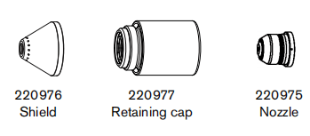
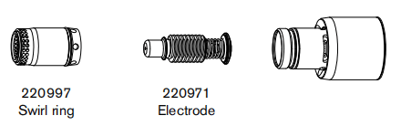
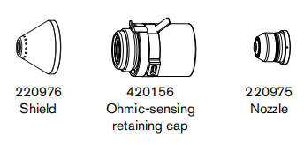
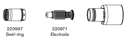
125 A shielded cutting – mild steel
| Air flow rate – slpm/scfh | |
| Hot | 260 / 550 |
| Cold | 345 / 730 |
Metric
| Material Thickness | Torch-to-Work Distance | Initial Pierce Height | Pierce Delay Time | Best Quality Settings | Production Settings | |||
| Cut Speed | Voltage | Cut Speed | Voltage | |||||
| mm | mm | mm | % | seconds | mm/min | volts | mm/min | volts |
| 6 | 4.6 | 9.2 | 200 | 0.2 | 4980 | 158 | 5960 | 155 |
| 8 | 0.3 | 3800 | 158 | 4570 | 157 | |||
| 10 | 0.4 | 2750 | 158 | 3330 | 158 | |||
| 12 | 0.5 | 2050 | 157 | 2510 | 157 | |||
| 16 | 11.5 | 250 | 0.6 | 1260 | 162 | 1660 | 164 | |
| 20 | 2.0 | 980 | 165 | 1140 | 164 | |||
| 25 | 3.5 | 610 | 169 | 780 | 167 | |||
| 30 | Edge Start* | 1.0 | 580 | 169 | 510 | 167 | ||
| 32 | 400 | 174 | 500 | 172 | ||||
| 35 | 340 | 177 | 430 | 175 | ||||
| 40 | 240 | 180 | 310 | 178 | ||||
English
| Material Thickness | Torch-to-Work Distance | Initial Pierce Height | Pierce Delay Time | Best Quality Settings | Production Settings | |||
| Cut Speed | Voltage | Cut Speed | Voltage | |||||
| inches | inches | inches | % | seconds | ipm | volts | ipm | volts |
| 1/4 | 0.18 | 0.36 | 200 | 0.2 | 188 | 158 | 225 | 155 |
| 3/8 | 0.4 | 114 | 158 | 138 | 158 | |||
| 1/2 | 0.5 | 75 | 158 | 93 | 158 | |||
| 5/8′ | 0.45 | 250 | 0.6 | 50 | 162 | 66 | 164 | |
| 3/4 | 0.8 | 42 | 164 | 48 | 163 | |||
| 7/8 | 2.0 | 31 | 168 | 37 | 166 | |||
| 1 | 3.5 | 23 | 169 | 30 | 167 | |||
| 1-1/4 | Edge Start* | 1.0 | 16 | 174 | 20 | 172 | ||
| 1-1/2 | 11 | 179 | 14 | 177 | ||||
* You can pierce thicknesses up to 32 mm (1-1/4 inch) if your CNC software and torch height control system enable you to temporarily raise the torch in order to clear the puddle of dross that can form during the pierce. In Hypertherm’s Phoenix CNC software, for example, this function is referred to as the “puddle jump height.” Using this piercing function may affect consumable life.
125 A shielded cutting – stainless steel
| Air flow rate – slpm/scfh | |
| Hot | 260 / 550 |
| Cold | 345 / 730 |
Metric
| Material Thickness | Torch-to-Work Distance | Initial Pierce Height | Pierce Delay Time | Best Quality Settings | Production Settings | |||
| Cut Speed | Voltage | Cut Speed | Voltage | |||||
| mm | mm | mm | % | seconds | mm/min | volts | mm/min | volts |
| 6 | 4.6 | 9.2 | 200 | 0.2 | 5910 | 156 | 5960 | 155 |
| 8 | 0.3 | 4060 | 157 | 4570 | 157 | |||
| 10 | 0.4 | 2540 | 159 | 3330 | 158 | |||
| 12 | 0.5 | 2170 | 163 | 2510 | 157 | |||
| 16 | 11.5 | 250 | 0.6 | 1140 | 165 | 1660 | 164 | |
| 20 | 2.0 | 940 | 167 | 1140 | 164 | |||
| 25 | 3.5 | 540 | 172 | 780 | 167 | |||
| 30 | Edge Start* | 1.0 | 510 | 173 | 510 | 167 | ||
| 32 | 400 | 177 | 500 | 172 | ||||
| 35 | 320 | 180 | 430 | 175 | ||||
| 40 | 180 | 185 | 310 | 178 | ||||
English
| Material Thickness | Torch-to-Work Distance | Initial Pierce Height | Pierce Delay Time | Best Quality Settings | Production Settings | |||
| Cut Speed | Voltage | Cut Speed | Voltage | |||||
| inches | inches | inches | % | seconds | ipm | volts | ipm | volts |
| 1/4 | 0.18 | 0.36 | 200 | 0.5 | 220 | 156 | 288 | 157 |
| 3/8 | 104 | 158 | 154 | 157 | ||||
| 1/2 | 78 | 163 | 98 | 158 | ||||
| 5/8′ | 0.45 | 250 | 0.7 | 45 | 165 | 58 | 162 | |
| 3/4 | 1.2 | 40 | 167 | 43 | 163 | |||
| 7/8 | 0.8 | 30 | 168 | 35 | 164 | |||
| 1 | 1.0 | 20 | 173 | 29 | 166 | |||
| 1-1/4 | Edge Start* | 1.1 | 16 | 177 | 24 | 169 | ||
| 1-1/2 | 1.2 | 9 | 183 | 12 | 177 | |||
125 A shielded cutting – aluminum
| Air flow rate – slpm/scfh | |
| Hot | 260 / 550 |
| Cold | 345 / 730 |
Metric
| Material Thickness | Torch-to-Work Distance | Initial Pierce Height | Pierce Delay Time | Best Quality Settings | Production Settings | |||
| Cut Speed | Voltage | Cut Speed | Voltage | |||||
| mm | mm | mm | % | seconds | mm/min | volts | mm/min | volts |
| 6 | 4.6 | 9.2 | 200 | 0.2 | 7660 | 159 | 8560 | 156 |
| 8 | 0.3 | 5100 | 161 | 6100 | 157 | |||
| 10 | 0.4 | 2980 | 163 | 4020 | 159 | |||
| 12 | 0.5 | 2140 | 165 | 3070 | 162 | |||
| 16 | 11.5 | 250 | 0.6 | 1540 | 169 | 2090 | 163 | |
| 20 | 2.0 | 1260 | 170 | 1500 | 167 | |||
| 25 | 3.5 | 850 | 174 | 1050 | 167 | |||
| 30 | Edge Start* | 1.0 | 810 | 175 | 760 | 167 | ||
| 32 | 430 | 182 | 750 | 174 | ||||
| 35 | 370 | 183 | 580 | 176 | ||||
| 40 | 270 | 185 | 300 | 179 | ||||
English
| Material Thickness | Torch-to-Work Distance | Initial Pierce Height | Pierce Delay Time | Best Quality Settings | Production Settings | |||
| Cut Speed | Voltage | Cut Speed | Voltage | |||||
| inches | inches | inches | % | seconds | ipm | volts | ipm | volts |
| 1/4 | 0.18 | 0.36 | 200 | 0.2 | 284 | 159 | 320 | 156 |
| 3/8 | 0.4 | 124 | 163 | 166 | 158 | |||
| 1/2 | 0.5 | 80 | 166 | 114 | 162 | |||
| 5/8 | 0.45 | 250 | 0.6 | 61 | 169 | 83 | 162 | |
| 3/4 | 0.8 | 52 | 170 | 62 | 163 | |||
| 7/8 | 2.0 | 44 | 171 | 52 | 167 | |||
| 1 | 3.5 | 32 | 175 | 40 | 167 | |||
| 1-1/4 | Edge Start* | 1.0 | 17 | 182 | 30 | 174 | ||
| 1-1/2 | 12 | 184 | 16 | 178 | ||||
105 A shielded consumables
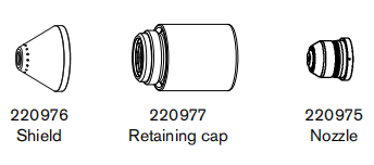
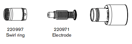
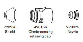
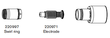
105 A shielded cutting – mild steel
| Air flow rate – slpm/scfh | |
| Hot | 260 / 550 |
| Cold | 345 / 730 |
Metric
| Material Thickness | Torch-to-Work Distance | Initial Pierce Height | Pierce Delay Time | Best Quality Settings | Production Settings | |||
| Cut Speed | Voltage | Cut Speed | Voltage | |||||
| mm | mm | mm | % | seconds | mm/min | volts | mm/min | volts |
| 6 | 4.6 | 9.2 | 200 | 0.5 | 4110 | 158 | 4920 | 146 |
| 8 | 0.6 | 3220 | 158 | 3770 | 150 | |||
| 10 | 0.8 | 2410 | 159 | 2730 | 153 | |||
| 12 | 0.7 | 1810 | 163 | 1980 | 156 | |||
| 16 | 11.5 | 250 | 1.0 | 1050 | 165 | 1230 | 155 | |
| 20 | 1.3 | 780 | 168 | 850 | 157 | |||
| 25 | 1.0 | 540 | 174 | 580 | 162 | |||
| 30 | Edge Start* | 1.2 | 420 | 176 | 440 | 168 | ||
| 32 | 370 | 177 | 400 | 170 | ||||
| 35 | 370 | 183 | 580 | 176 | ||||
| 40 | 270 | 185 | 300 | 179 | ||||
English
| Material Thickness | Torch-to-Work Distance | Initial Pierce Height | Pierce Delay Time | Best Quality Settings | Production Settings | |||
| Cut Speed | Voltage | Cut Speed | Voltage | |||||
| inches | inches | inches | % | seconds | ipm | volts | ipm | volts |
| 1/4 | 0.18 | 0.36 | 200 | 0.5 | 156 | 158 | 186 | 147 |
| 3/8 | 0.75 | 100 | 158 | 114 | 152 | |||
| 1/2 | 0.75 | 66 | 163 | 73 | 156 | |||
| 5/8 | 0.45 | 250 | 1 | 42 | 165 | 49 | 155 | |
| 3/4 | 1 | 33 | 168 | 35 | 156 | |||
| 7/8 | 2.0 | 26 | 169 | 30 | 158 | |||
| 1 | Edge Start* | 1.0 | 21 | 175 | 22 | 163 | ||
| 1-1/4 | 1.2 | 15 | 177 | 16 | 170 | |||
105 A shielded cutting – stainless steel
| Air flow rate – slpm/scfh | |
| Hot | 260 / 550 |
| Cold | 345 / 730 |
Metric
| Material Thickness | Torch-to-Work Distance | Initial Pierce Height | Pierce Delay Time | Best Quality Settings | Production Settings | |||
| Cut Speed | Voltage | Cut Speed | Voltage | |||||
| mm | mm | mm | % | seconds | mm/min | volts | mm/min | volts |
| 6 | 4.6 | 9.2 | 200 | 0.5 | 5320 | 158 | 5780 | 144 |
| 8 | 3650 | 159 | 3940 | 148 | ||||
| 10 | 2230 | 160 | 2420 | 151 | ||||
| 12 | 1460 | 162 | 1980 | 154 | ||||
| 16 | 11.5 | 250 | 1.0 | 1050 | 166 | 950 | 156 | |
| 20 | 2.5 | 660 | 169 | 730 | 158 | |||
| 25 | Edge Start* | 1.0 | 440 | 174 | 520 | 162 | ||
| 30 | 330 | 176 | 450 | 167 | ||||
| 32 | 1.2 | 290 | 177 | 420 | 169 | |||
English
| Material Thickness | Torch-to-Work Distance | Initial Pierce Height | Pierce Delay Time | Best Quality Settings | Production Settings | |||
| Cut Speed | Voltage | Cut Speed | Voltage | |||||
| inches | inches | inches | % | seconds | ipm | volts | ipm | volts |
| 1/4 | 0.18 | 0.36 | 200 | 0.5 | 198 | 158 | 224 | 145 |
| 3/8 | 94 | 160 | 100 | 150 | ||||
| 1/2 | 55 | 163 | 71 | 154 | ||||
| 5/8 | 0.45 | 250 | 1.0 | 42 | 166 | 38 | 156 | |
| 3/4 | 2.5 | 28 | 168 | 30 | 157 | |||
| 7/8 | Edge Start* | 1.0 | 22 | 172 | 26 | 159 | ||
| 1 | 17 | 174 | 20 | 163 | ||||
| 1-1/4 | 1.2 | 12 | 177 | 17 | 169 | |||
105 A shielded cutting – aluminum
| Air flow rate – slpm/scfh | |
| Hot | 260 / 550 |
| Cold | 345 / 730 |
Metric
| Material Thickness | Torch-to-Work Distance | Initial Pierce Height | Pierce Delay Time | Best Quality Settings | Production Settings | |||
| Cut Speed | Voltage | Cut Speed | Voltage | |||||
| mm | mm | mm | % | seconds | mm/min | volts | mm/min | volts |
| 6 | 4.6 | 9.2 | 200 | 0.5 | 6340 | 158 | 6390 | 154 |
| 8 | 0.6 | 4330 | 162 | 4690 | 154 | |||
| 10 | 0.8 | 2660 | 164 | 3250 | 155 | |||
| 12 | 0.7 | 2020 | 167 | 2590 | 159 | |||
| 16 | 11.5 | 250 | 1.0 | 1350 | 169 | 1550 | 157 | |
| 20 | 1.3 | 970 | 172 | 1020 | 161 | |||
| 25 | Edge Start* | 1.0 | 660 | 176 | 800 | 167 | ||
| 30 | 460 | 180 | 580 | 174 | ||||
| 32 | 1.2 | 290 | 182 | 490 | 176 | |||
English
| Material Thickness | Torch-to-Work Distance | Initial Pierce Height | Pierce Delay Time | Best Quality Settings | Production Settings | |||
| Cut Speed | Voltage | Cut Speed | Voltage | |||||
| inches | inches | inches | % | seconds | ipm | volts | ipm | volts |
| 1/4 | 0.18 | 0.36 | 200 | 0.5 | 236 | 159 | 240 | 154 |
| 3/8 | 0.75 | 110 | 164 | 134 | 154 | |||
| 1/2 | 75 | 167 | 95 | 159 | ||||
| 5/8 | 0.45 | 250 | 1.0 | 54 | 169 | 62 | 157 | |
| 3/4 | 40 | 171 | 42 | 160 | ||||
| 7/8 | 2.0 | 34 | 173 | 37 | 164 | |||
| 1 | Edge Start* | 1.0 | 25 | 176 | 31 | 167 | ||
| 1-1/4 | 1.2 | 16 | 182 | 20 | 176 | |||
65 A shielded consumables
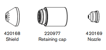
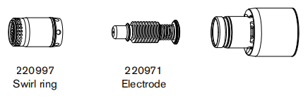
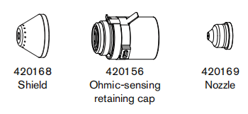
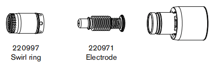
65 A shielded cutting – mild steel
| Air flow rate – slpm/scfh | |
| Hot | 260 / 550 |
| Cold | 345 / 730 |
Metric
| Material Thickness | Torch-to-Work Distance | Initial Pierce Height | Pierce Delay Time | Best Quality Settings | Production Settings | |||
| Cut Speed | Voltage | Cut Speed | Voltage | |||||
| mm | mm | mm | % | seconds | mm/min | volts | mm/min | volts |
| 2 | 1.5 | 3.8 | 250 | 0.1 | 5930 | 158 | 6390 | 123 |
| 3 | 0.2 | 5150 | 162 | 4690 | 123 | |||
| 4 | 0.5 | 4370 | 164 | 3250 | 123 | |||
| 6 | 2815 | 167 | 2590 | 124 | ||||
| 8 | 2080 | 169 | 1550 | 126 | ||||
| 10 | 4.5 | 300 | 0.7 | 1520 | 172 | 1020 | 128 | |
| 12 | 1.2 | 660 | 176 | 800 | 130 | |||
| 16 | 6 | 400 | 2.0 | 460 | 180 | 580 | 135 | |
| 20 | Edge Start* | 290 | 182 | 490 | 140 | |||
| 25 | 215 | 146 | 270 | 146 | ||||
English
| Material Thickness | Torch-to-Work Distance | Initial Pierce Height | Pierce Delay Time | Best Quality Settings | Production Settings | |||
| Cut Speed | Voltage | Cut Speed | Voltage | |||||
| inches | inches | inches | % | seconds | ipm | volts | ipm | volts |
| 16 GA | 0.06 | 0.15 | 250 | 0.1 | 248 | 122 | 294 | 122 |
| 10 GA | 190 | 123 | 224 | 123 | ||||
| 3/16 | 0.2 | 149 | 124 | 174 | 123 | |||
| 1/4 | 0.5 | 100 | 125 | 116 | 124 | |||
| 3/8 | 0.7 | 65 | 129 | 62 | 128 | |||
| 1/2 | 0.18 | 300 | 1.2 | 30 | 132 | 40 | 131 | |
| 5/8 | 0.24 | 400 | 2 | 23 | 136 | 30 | 135 | |
| 3/4 | Edge Start | 15 | 140 | 19 | 139 | |||
| 7/8 | 12 | 143 | 15 | 143 | ||||
| 1 | 8 | 146 | 10 | 146 | ||||
65 A shielded cutting – stainless steel
| Air flow rate – slpm/scfh | |
| Hot | 260 / 550 |
| Cold | 345 / 730 |
Metric
| Material Thickness | Torch-to-Work Distance | Initial Pierce Height | Pierce Delay Time | Best Quality Settings | Production Settings | |||
| Cut Speed | Voltage | Cut Speed | Voltage | |||||
| mm | mm | mm | % | seconds | mm/min | volts | mm/min | volts |
| 2 | 1.5 | 3.8 | 250 | 0.1 | 7405 | 119 | 9970 | 121 |
| 3 | 0.2 | 6120 | 120 | 8240 | 122 | |||
| 4 | 0.5 | 4840 | 122 | 6110 | 123 | |||
| 6 | 2275 | 125 | 2840 | 125 | ||||
| 8 | 0.7 | 1505 | 127 | 1860 | 127 | |||
| 10 | 4.5 | 300 | 1115 | 130 | 1245 | 128 | ||
| 12 | 1.2 | 720 | 133 | 925 | 130 | |||
| 16 | Edge Start | 465 | 137 | 505 | 136 | |||
| 20 | 320 | 141 | 345 | 141 | ||||
English
| Material Thickness | Torch-to-Work Distance | Initial Pierce Height | Pierce Delay Time | Best Quality Settings | Production Settings | |||
| Cut Speed | Voltage | Cut Speed | Voltage | |||||
| inches | inches | inches | % | seconds | ipm | volts | ipm | volts |
| 16 GA | 0.06 | 0.15 | 250 | 0.1 | 316 | 118 | 425 | 120 |
| 10 GA | 220 | 121 | 296 | 122 | ||||
| 3/16 | 0.2 | 152 | 123 | 168 | 123 | |||
| 1/4 | 0.5 | 72 | 125 | 96 | 125 | |||
| 3/8 | 0.7 | 48 | 130 | 52 | 128 | |||
| 1/2 | 0.18 | 300 | 1.2 | 23 | 134 | 32 | 131 | |
| 5/8 | Edge Start | 19 | 137 | 20 | 136 | |||
| 3/4 | 14 | 140 | 15 | 140 | ||||
65 A shielded cutting – stainless steel
| Air flow rate – slpm/scfh | |
| Hot | 260 / 550 |
| Cold | 345 / 730 |
Metric
| Material Thickness | Torch-to-Work Distance | Initial Pierce Height | Pierce Delay Time | Best Quality Settings | Production Settings | |||
| Cut Speed | Voltage | Cut Speed | Voltage | |||||
| mm | mm | mm | % | seconds | mm/min | volts | mm/min | volts |
| 2 | 1.5 | 3.8 | 250 | 0.1 | 7805 | 123 | 10265 | 122 |
| 3 | 0.2 | 6565 | 125 | 8790 | 123 | |||
| 4 | 0.5 | 5320 | 126 | 7320 | 124 | |||
| 6 | 2845 | 129 | 4375 | 126 | ||||
| 8 | 0.7 | 2015 | 133 | 2750 | 129 | |||
| 10 | 4.5 | 300 | 1535 | 136 | 1650 | 132 | ||
| 12 | 1.2 | 1055 | 139 | 1330 | 135 | |||
| 16 | Edge Start | 640 | 143 | 805 | 140 | |||
| 20 | 335 | 146 | 550 | 144 | ||||
English
| Material Thickness | Torch-to-Work Distance | Initial Pierce Height | Pierce Delay Time | Best Quality Settings | Production Settings | |||
| Cut Speed | Voltage | Cut Speed | Voltage | |||||
| inches | inches | inches | % | seconds | ipm | volts | ipm | volts |
| 1/16 | 0.06 | 0.15 | 250 | 0.1 | 328 | 123 | 428 | 122 |
| 1/8 | 250 | 125 | 336 | 123 | ||||
| 1/4 | 0.5 | 95 | 130 | 152 | 126 | |||
| 3/8 | 0.7 | 65 | 135 | 68 | 131 | |||
| 1/2 | 0.18 | 300 | 1.2 | 35 | 140 | 48 | 136 | |
| 5/8 | Edge Start | 26 | 143 | 32 | 140 | |||
| 3/4 | 16 | 145 | 24 | 143 | ||||
45 A shielded consumables
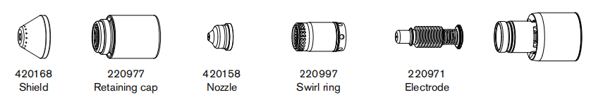
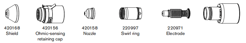
45 A shielded cutting – mild steel
| Air flow rate – slpm/scfh | |
| Hot | 217 / 460 |
| Cold | 241 / 5 10 |
Metric
| Material Thickness | Torch-to-Work Distance | Initial Pierce Height | Pierce Delay Time | Best Quality Settings | Production Settings | |||
| Cut Speed | Voltage | Cut Speed | Voltage | |||||
| mm | mm | mm | % | seconds | mm/min | volts | mm/min | volts |
| 0.5 | 0.5 | 2.0 | 400 | 0.0 | 8890 | 118 | 12510 | 120 |
| 1 | 8890 | 119 | 10760 | 120 | ||||
| 1.5 | 0.1 | 8040 | 123 | 10160 | 123 | |||
| 2 | 1.5 | 3.8 | 250 | 0.3 | 6565 | 128 | 7770 | 125 |
| 3 | 0.4 | 3720 | 129 | 4890 | 128 | |||
| 4 | 2250 | 130 | 3550 | 130 | ||||
| 6 | 0.5 | 1265 | 132 | 2050 | 130 | |||
English
| Material Thickness | Torch-to-Work Distance | Initial Pierce Height | Pierce Delay Time | Best Quality Settings | Production Settings | |||
| Cut Speed | Voltage | Cut Speed | Voltage | |||||
| inches | inches | inches | % | seconds | ipm | volts | ipm | volts |
| 26 GA | 0.02 | 0.08 | 400 | 0.0 | 350 | 118 | 500 | 120 |
| 22 GA | 350 | 118 | 450 | 120 | ||||
| 18 GA | 0.1 | 350 | 119 | 400 | 120 | |||
| 16 GA | 324 | 123 | 400 | 123 | ||||
| 14 GA | 0.06 | 0.15 | 250 | 0.2 | 270 | 128 | 320 | 125 |
| 12 GA | 0.4 | 185 | 129 | 216 | 127 | |||
| 10 GA | 100 | 130 | 164 | 130 | ||||
| 3/16 | 0.5 | 74 | 131 | 108 | 130 | |||
| 1/4 | 0.6 | 43 | 132 | 73 | 130 | |||
45 A shielded cutting – stainless steel
| Air flow rate – slpm/scfh | |
| Hot | 217 / 460 |
| Cold | 241 / 5 10 |
Metric
| Material Thickness | Torch-to-Work Distance | Initial Pierce Height | Pierce Delay Time | Best Quality Settings | Production Settings | |||
| Cut Speed | Voltage | Cut Speed | Voltage | |||||
| mm | mm | mm | % | seconds | mm/min | volts | mm/min | volts |
| 0.5 | 0.5 | 2.0 | 400 | 0.0 | 8890 | 113 | 12510 | 120 |
| 1 | 8890 | 113 | 10760 | 120 | ||||
| 1.5 | 0.1 | 7825 | 117 | 10160 | 120 | |||
| 2 | 1.5 | 3.8 | 250 | 0.3 | 6095 | 122 | 8615 | 122 |
| 3 | 0.4 | 3585 | 123 | 4405 | 123 | |||
| 4 | 2185 | 126 | 2565 | 126 | ||||
| 6 | 0.5 | 975 | 132 | 1020 | 132 | |||
English
| Material Thickness | Torch-to-Work Distance | Initial Pierce Height | Pierce Delay Time | Best Quality Settings | Production Settings | |||
| Cut Speed | Voltage | Cut Speed | Voltage | |||||
| inches | inches | inches | % | seconds | ipm | volts | ipm | volts |
| 26 GA | 0.02 | 0.08 | 400 | 0.0 | 350 | 113 | 500 | 120 |
| 22 GA | 350 | 113 | 450 | 120 | ||||
| 18 GA | 0.1 | 350 | 113 | 400 | 120 | |||
| 16 GA | 305 | 117 | 400 | 120 | ||||
| 14 GA | 0.06 | 0.15 | 250 | 0.2 | 250 | 122 | 360 | 122 |
| 12 GA | 0.4 | 175 | 123 | 206 | 123 | |||
| 10 GA | 100 | 124 | 134 | 124 | ||||
| 3/16 | 0.5 | 68 | 128 | 58 | 128 | |||
| 1/4 | 0.6 | 30 | 133 | 35 | 133 | |||
45 A shielded cutting – aluminum
| Air flow rate – slpm/scfh | |
| Hot | 217 / 460 |
| Cold | 241 / 5 10 |
Metric
| Material Thickness | Torch-to-Work Distance | Initial Pierce Height | Pierce Delay Time | Best Quality Settings | Production Settings | |||
| Cut Speed | Voltage | Cut Speed | Voltage | |||||
| mm | mm | mm | % | seconds | mm/min | volts | mm/min | volts |
| 1 | 1.5 | 3.8 | 250 | 0.0 | 9145 | 126 | 11100 | 124 |
| 2 | 0.1 | 7470 | 125 | 9210 | 124 | |||
| 3 | 0.2 | 4675 | 125 | 6190 | 125 | |||
| 4 | 0.4 | 3700 | 129 | 4845 | 127 | |||
| 6 | 0.5 | 1740 | 135 | 2795 | 132 | |||
English
| Material Thickness | Torch-to-Work Distance | Initial Pierce Height | Pierce Delay Time | Best Quality Settings | Production Settings | |||
| Cut Speed | Voltage | Cut Speed | Voltage | |||||
| inches | inches | inches | % | seconds | ipm | volts | ipm | volts |
| 1/32 | 0.06 | 0.15 | 250 | 0.0 | 360 | 126 | 450 | 124 |
| 1/16 | 0.1 | 360 | 126 | 400 | 124 | |||
| 3/32 | 0.2 | 233 | 124 | 326 | 124 | |||
| 1/8 | 0.4 | 177 | 126 | 224 | 125 | |||
| 1/4 | 0.5 | 55 | 136 | 96 | 133 | |||
FineCut consumables
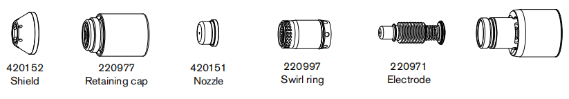
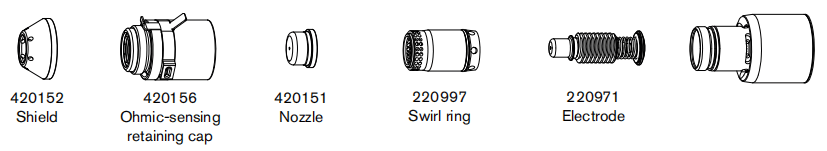
FineCut – mild steel
| Air flow rate – slpm/scfh | |
| Hot | 217 / 460 |
| Cold | 226/480 |
Metric
| Material Thickness | Current | Torch-to-Work Distance | Initial Pierce Height | Pierce Delay Time | Recommended | ||
| Cut Speed | Voltage | ||||||
| mm | A | mm | mm | % | seconds | mm/min | volts |
| 0.5 | 30 | 1.5 | 2.25 | 150 | 0.0 | 4330 | 83 |
| 0.6 | 4080 | 85 | |||||
| 0.8 | 0.1 | 4065 | 85 | ||||
| 1 | 40 | 0.2 | 4825 | 81 | |||
| 1.5 | 0.4 | 4825 | 79 | ||||
| 2 | 45 | 4740 | 78 | ||||
| 3 | 0.5 | 3445 | 80 | ||||
| 4 | 1270 | 80 | |||||
English
| Material Thickness | Current | Torch-to-Work Distance | Initial Pierce Height | Pierce Delay Time | Recommended | ||
| Cut Speed | Voltage | ||||||
| inches | A | inches | inches | % | seconds | ipm | volts |
| 26 GA | 30 | 0.06 | 0.09 | 150 | 0.0 | 175 | 82 |
| 24 GA | 160 | 85 | |||||
| 22 GA | 0.1 | 160 | 85 | ||||
| 20 GA | 160 | 85 | |||||
| 18 GA | 40 | 0.2 | 190 | 80 | |||
| 16 GA | 0.4 | 190 | 79 | ||||
| 14 GA | 45 | 190 | 78 | ||||
| 12 GA | 0.5 | 165 | 80 | ||||
| 10 GA | 100 | 80 | |||||
FineCut – stainless steel
| Air flow rate – slpm/scfh | |
| Hot | 217 / 460 |
| Cold | 226/480 |
Metric
| Material Thickness | Current | Torch-to-Work Distance | Initial Pierce Height | Pierce Delay Time | Recommended | ||
| Cut Speed | Voltage | ||||||
| mm | A | mm | mm | % | seconds | mm/min | volts |
| 0.5 | 30 | 0.0 | 0.08 | 400 | 0.0 | 4825 | 77 |
| 0.6 | 4825 | 77 | |||||
| 0.8 | 0.1 | 4825 | 73 | ||||
| 1 | 40 | 0.2 | 4825 | 86 | |||
| 1.5 | 0.4 | 4825 | 72 | ||||
| 2 | 45 | 4550 | 72 | ||||
| 3 | 0.5 | 2335 | 70 | ||||
| 4 | 995 | 72 | |||||
English
| Material Thickness | Current | Torch-to-Work Distance | Initial Pierce Height | Pierce Delay Time | Recommended | ||
| Cut Speed | Voltage | ||||||
| inches | A | inches | inches | % | seconds | ipm | volts |
| 26 GA | 30 | 0.02 | 0.08 | 400 | 0.0 | 190 | 77 |
| 24 GA | 190 | 77 | |||||
| 22 GA | 0.1 | 190 | 74 | ||||
| 20 GA | 190 | 72 | |||||
| 18 GA | 40 | 0.2 | 190 | 80 | |||
| 16 GA | 0.4 | 190 | 72 | ||||
| 14 GA | 45 | 190 | 72 | ||||
| 12 GA | 0.5 | 110 | 70 | ||||
| 10 GA | 70 | 71 | |||||
Section 7
Mechanized Cutting
Connecting an optional remote-start pendant
Powermax125 configurations with a Duramax Hyamp machine torch can include an optional remote-start pendant.
■ Part number 128650: 7.6 m (25 feet)
■ Part number 128651: 15 m (50 feet)
■ Part number 128652: 23 m (75 feet)
Remove the machine interface receptacle cover on the rear of the power supply, and plug the Hypertherm remote-start pendant into the receptacle.
The remote-start pendant is for use only with a machine torch. It will not operate if a handheld torch is installed.
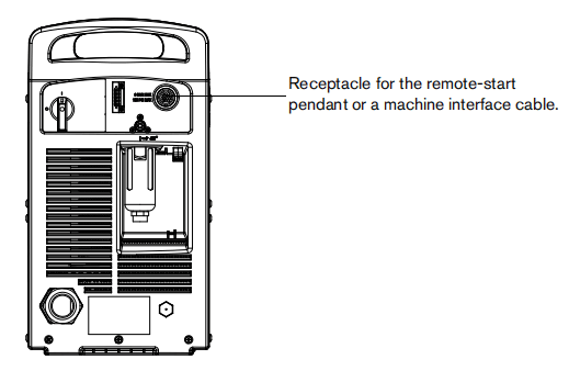
Connecting the machine interface cable
The Powermax125 is equipped with a factory-installed five-position voltage divider board. The built-in voltage dividerprovides a scaled down arc voltage of 20:1, 21.1:1, 30:1, 40:1, or 50:1 (maximum output of 16 V).
A receptacle on the rear of the power supply (see the previous illustration) provides access to the scaled down arc voltage and signals for arc transfer and plasma start.
The factory presets the voltage divider to 50:1. To change the voltage divider to a different setting, refer to Setting the five-position voltage divider on page 101.
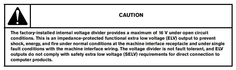
•••Hypertherm offers several choices of machine interface cables:
■ To use the built-in voltage divider that provides a scaled down arc voltage in addition to signals for arc transfer and plasma start:
□ Use part number 228350 (7.6 m, 25 feet) or 228351 (15 m, 50 feet) for wires terminated with spade connectors.
□ Use one of the following part numbers for a cable terminated with a D-sub connector. (Compatible with Hypertherm products, such as EDGE® Pro Ti and Sensor™ PHC.)
• 223354 (3.0 m, 10 feet)
• 223355 (6.1 m, 20 feet)
• 223048 (7.6 m, 25 feet)
• 223356 (10.7 m, 35 feet)
• 123896 (15 m, 50 feet)
■ To use signals for arc transfer and plasma start only, use either part number 023206 (7.6 m, 25 feet) or part number 023279 (15 m, 50 feet).
These cables have spade connectors as follows:
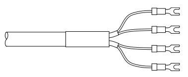
Refer to Machine interface pinout on page 10 0 for receptacle pinout information.
The cover on the machine interface receptacle prevents dust and moisture from damaging the receptacle when not in use. This cover should be replaced if damaged or lost (part number 127204).
Refer to Parts on page 117 for more information.
Installation of the machine interface cable must be performed by a qualified service technician. To install a machine interface cable:
- Turn OFF the power and disconnect the power cord.
- Remove the machineinterface receptacle’s cover from the rear of the power supply.
- Connect the Hypertherm machine interface cable to the power supply.
- If you are using a cable with a D-sub connectoron the other end, plug it into the appropriate pin connector on the torch height controller or CNC. Secure it with the screws on the D-sub connector.
If you are using a cable with wires and spade connectors on the other end, terminate the machine interface cable inside the electrical enclosure of the torch height controller or CNC controller to prevent unauthorized access to the connections after installation. Verify that the connections are correct and that all live parts are enclosed and protected before operating the equipment.
The integration of Hypertherm equipment and customer-supplied equipment including interconnecting cords and cables, if not listed and certified as a system, is subject to inspection by local authorities at the final installation site.
The connector sockets for each type of signal available through the machine interface cable are shown in Figure 2.Table 10 on page 100 provides details about each signal type.
Machine interface pinout
Figure 2 – Connector sockets

Refer to Table 10 when connecting the power supply to a torch height controller or CNC controller with a machine interface cable.
Table 10 – Machine interface cable signals
| Signal | Type | Notes | Connector sockets | External cable wires |
| Start (start plasma) | Input | Normally open. 18 VDC open circuit voltage at START terminals. Requires dry contact closure to activate. | 3, 4 | Green, black |
| Transfer (start machine motion) | Output | Normally open. Dry contact closure when the arc transfers.120 VAC/1 A maximum at the machine interface relay. | 12, 14 | Red, black |
| Ground | Ground | 13 | ||
| Voltage divider | Output | Divided arc signal of 20:1, 21.1:1, 30:1, 40:1, 50:1 (provides amaximum of 16 V). | 5 (-), 6 (+) | Black (-), white (+) |
Setting the five-position voltage divider
To change the factory preset voltage divider from 50:1 to a different setting.
- Turn OFF the power and disconnect the power cord.
- Remove the power supply cover.
- Locate the voltage divider DIP switches on the left side of the power supply.
Figure 3 shows the default setting (50:1) with the number 4 switch up.
Figure 3- Voltage divider at default setting(50:1)
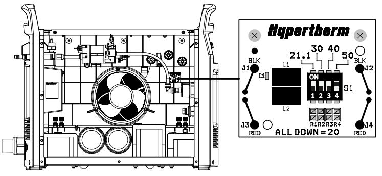
4. Set the DIP switches to one of the following settings, and replace the power supply cover.
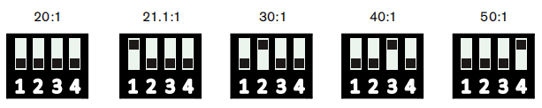
If the Hypertherm five-position voltage divider does not supply the required voltage for your application, contact your system integrator for assistance.
Accessing raw arc voltage
To access divided raw arc voltage, refer to Field Service Bulletin 807060.
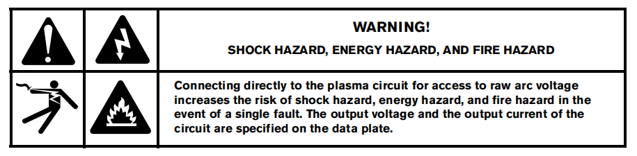
Connecting an optional RS-485 serial interface cable
The RS-485 serial interface connector on the back of the power supply allows you to connect an external device to your Powermax.
For example, you can remotely operate the Powermax with a CNC controller.
The Powermax power supply must be equipped with a factory-installed (or user-installed) RS-485 serial interface connector on the rear panel. The receptacle on the rear of the power supply provides access to the RS-485 board inside the power supply.
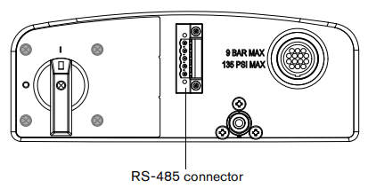
With the RS-485 connector installed:
- Shut OFF the power supply.
- Connect the RS-485 cable from your external device to the receptacle on the back of the Powermax power supply.
Serial port cables
The following serial cables are available with the specified lengths and connectors:
■ 223236 – RS-485 cable, unterminated, 7.6 m (25 feet)
■ 223237 – RS-485 cable, unterminated, 15 m (50 feet)
■ 223239 – RS-485 cable, 9-pin D-sub connector for Hypertherm controls, 7.6 m (25 feet)
■ 223240 – RS-485 cable, 9-pin D-sub connector for Hypertherm controls, 15 m (50 feet)
Using the machine torch
Since the Powermax with a machine torch can be used with a wide variety of cutting tables, track burners, pipe bevelers,and so on, you will need to refer to the manufacturer’s instructions for specifics on operating the machine torch in your configuration. However, the following topics will help you optimize cut quality and maximize consumable life.
Setting up the torch and table
■ Use a square to align the torch at right angles to the workpiece in two dimensions.
■ The torch may travel more smoothly if you clean, check, and “tune” the cutting table’s rails and drive system. Unsteady machine motion can cause a regular, wavy pattern on the cut surface.
■ Ensure that the torch does not touch the workpiece during cutting. Contact with the workpiece can damage the shield and nozzle and affect the cut surface.
Understand and optimize cut quality
Several factors affect cut quality:
■ Cut angle – The degree of angularity of the cut edge.
■ Dross – The molten material that solidifies on the top or bottom of the workpiece.
■ Straightness of the cut surface – The cut surface can be concave or convex.
The following topics explain how these factors can affect cut quality.
Cut or bevel angle
■ A positive cut angle results when more material is removed from the top of the cut than from the bottom.
■ A negative cut angle results when more material is removed from the bottom of the cut.
Figure 4 – Cut angles
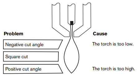
Solution
Raise the torch; or if you are using a torch height control, increase the arc voltage.
Lower the torch; or if you are using a torch height control, decrease the arc voltage.
The squarest cut angle will be on the right side with respect to the forward motion of the torch. The left side will always have some degree of cut angle.
To determine whether a cut-angle problem is being caused by the plasma system or the drive system, make a test cut and measure the angle of each side. Next, turn the torch 90° in its holder and repeat the process. If the angles are the same in both tests, the problem is in the drive system.
If a cut-angle problem persists after mechanical causes have been eliminated (see Setting up the torch and table on page 103), check the torch-to-work distance, especially if the cut angles are all positive or all negative. Also consider the material being cut: if the metal is magnetized or hardened, you are more likely to experience cut angle problems.
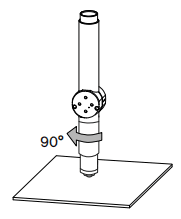
Dross
Some amount of dross will always be present when cutting with air plasma. However, you can minimize the amount and type of dross by adjusting your system correctly for your application.
Excess dross appears on the top edge of both pieces of the plate when the torch is too low (or voltage is too low whenusing a torch height control). Adjust the torch or adjust the voltage in small increments (5 volts or less) until the dross is reduced.
Low-speed dross forms when the torch’s cutting speed is too slow and the arc angles ahead. It forms as a heavy, bubbly deposit at the bottom of the cut and can be removed easily. Increase the speed to reduce this type of dross.
High-speed dross forms when the cutting speed is too fast and the arc angles behind. It forms as a thin, linear bead of solid metal attached very close to the cut. It is more firmly attached to the bottom of the cut than at low speed and isdifficult to remove. To reduce high-speed dross:
■ Decrease the cutting speed.
■ Decrease the torch-to-work distance.
Piercing a workpiece using the machine torch
As with the hand torch, you can start a cut with the machine torch at the edge of the workpiece or by piercing theworkpiece. Piercing may result in a shorter consumable life than with edge starts.
The cut charts include a column for the recommended torch height when starting a pierce. For the Powermax125, thepierce height is generally between 1.5 and 4 times the cut height. Refer to the cut charts for specific values.
The pierce delay must be long enough that the arc can pierce the material before the torch moves, but not so long that the arc “wanders” while trying to find the edge of a large hole. As consumables wear, this delay time may need to beincreased. Pierce delay times given in the cut charts are based on average delay times throughout the life of theconsumables.
When piercing materials close to the maximum thickness for a specific process, consider the following important factors:
■ Allow a lead-in distance approximately equal to the thickness of the material being pierced. For example, 20 mm (3/4 in) material requires a 20 mm lead-in.
■ To avoid damage to the shield from the buildup of molten material created by the pierce, do not allow the torch to descend to cut height until it has cleared the puddle of molten material.
■ Different material chemistries can have an adverse effect on the pierce capability of the system. In particular, high-strength steel with a high manganese or silicon content can reduce the maximum pierce capability. Hypertherm derives mild steel parameters using certified A-36 plate.
Common machine-cutting faults
The torch’s pilot arc will initiate, but will not transfer.
■ The work lead is not making good contact with the cutting table, or the cutting table is not making good contact with the workpiece.
■ The torch-to-work distance/cut height is too large.
The workpiece is not totally pierced, and there is excessive sparking on the top of the workpiece.
■ The metal surface is not clean of rust or paint.
■ The consumables are worn and need to be replaced. For optimized performance in a mechanized application, replace the nozzle and the electrode together.
■ The work lead is not making good contact with the cutting table, or the cutting table is not making good contact with the workpiece.
■ The current (amperage) is set too low. See Machine Torch Setup on page 65.
■ The cut speed is too high. See the cut charts under Using the cut charts on page 75.
■ The metal being cut exceeds the maximum capacity for the selected amperage. See Specifications on page 17.
Excessive dross forms on the bottom of the cut.
■ The gas setting is too high or too low.
■ The consumables are worn and need to be replaced. For optimized performance in a mechanized application, replace the nozzle and the electrode together.
■ The cutting speed is not correct. See the cut charts under Using the cut charts on page 75.
■ The current (amperage) is set too low. See the cut charts under Using the cut charts on page 75. The cut angle is not square.
■ The torch is not square to the workpiece.
■ The gas setting is incorrect.
■ The consumables are worn and need to be replaced. For optimized performance in a mechanized application, replace the nozzle and the electrode together.
■ The direction of the torch travel is incorrect. The high-quality cut is always on the right with respect to the forward motion of the torch.
■ The torch-to-work distance/cut height is too large or too small.
■ The cutting speed is not correct. See the cut charts under Using the cut charts on page 75. The consumable life is shortened.
■ The gas setting is incorrect.
■ The arc current, arc voltage, travel speed, and other variables are not set as recommended in the cut charts.
■ Firing the arc in the air (beginning or ending the cut off of the plate surface). Starting at the edge is acceptable as long as the arc makes contact with the workpiece when started.
■ Starting a pierce with an incorrect torch height. Refer to the cut charts for the specific initial pierce height.
■ The pierce time is incorrect.
■ The air quality is poor (oil or water in the air).
■ There might be a faulty pilot arc IGBT, which can shorten nozzle life (refer to Maintenance and Repair on page 107, or contact your closest Hypertherm technical service in the front of this manual).
■ The swirl ring or retaining cap is worn and needs to be replaced.
Section 8
Maintenance and Repair
Perform routine maintenance
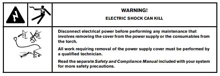
Routine maintenance tasks
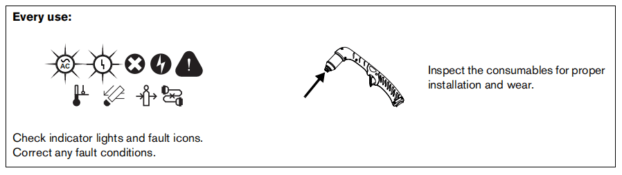
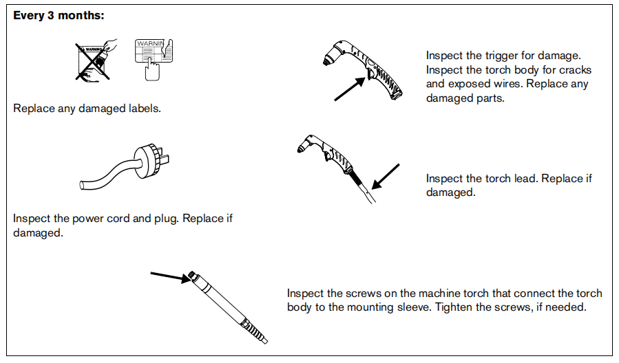

Inspect the Powermax125 consumables
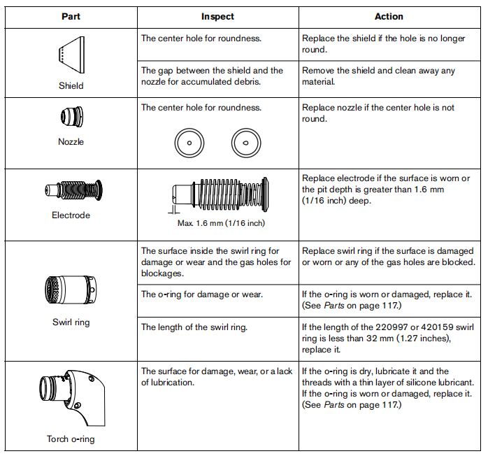
Basic troubleshooting
The following table provides an overview of the most common problems that can arise when using the system and explains how to solve them.
Fault icons and corresponding fault codes appear in the LCD display. See Fault codes and solutions on page 111.
If a fault occurs while using a generator, turn OFF the power supply, wait 60 to 70 seconds, and turn ON the power supply.
If you are unable to fix the problem by following this basic troubleshooting guide, or if you need further assistance:
- Call your Hypertherm distributor or authorized Hypertherm repair facility.
- Call the nearest Hypertherm office listed in the front of this manual.
Troubleshooting guide
• Inspect the consumable parts and replace them if they are worn or damaged. See Inspect the Powermax125 consumables on page 109.
• Replace the gas filter element if it is contaminated. See filter element on page 116.
• Make sure the gas pressure is at the proper level.
| Problem | Solutions |
| The ON/OFF power switch is set to ON (I), but the power ON LED is not illuminated. | • Verify that the power cord is plugged into the receptacle. • Verify that the power is ON at the main power panel or at the line-disconnect switch box. • Verify that the line voltage is not too low (more than 15% below the rated voltage). • Verify that the fuses in the disconnect are not blown. |
| The arc does not transfer to the workpiece. | • Clean the area where the ground clamp contacts the workpiece to ensure a good metal-to-metal connection. • Inspect the ground clamp for damage, and repair as necessary. • The pierce-height distance may be too large. Move the torch closer to the workpiece and fire the torch again. |
| The arc blows out, but re-ignites when the torch trigger is pressed again. | • Inspect the consumable parts and replace them if they are worn or damaged. See Inspect the Powermax125 consumables on page 109. • Replace the gas filter element if it is contaminated. See Replace the gas filter element on page 116. • Make sure the gas pressure is at the proper level. |
| The arc sputters and hisses. | • The gas filter element is contaminated. Replace the element. See Replace the gas filter element on page 116. • Inspect the gas line for moisture. If necessary, install or repair the gas filtration to the power supply. See Power Supply Setup on page 27. |
| The cut quality is poor. | • Verify that the torch is being used correctly. See Basic System Operations on page 37, Hand Cutting on page 55, or Mechanized Cutting on page 97. • Inspect the consumables for wear and replace as necessary. See Inspect the Powermax125 consumables on page 109. • Check the air pressure and air quality. • Verify that the cutting mode switch is in the proper position for the cutting operation. • Verify that the correct consumables are installed. |
Fault codes and solutions
A label with descriptions for these common fault codes can be found inside the front cover of the Operator Manual. Peel off the label and place it on the top of the power supply for reference.
If a fault occurs while using a generator, turning the power switch quickly to OFF and then to ON again (sometimes called a “quick reset” or “quick restart”) may not clear the fault.
Instead, turn OFF the power supply and wait 60 to 70 seconds before turning ON again.
Fault codes
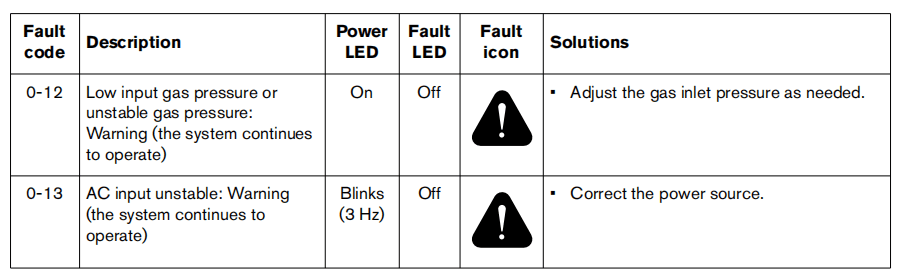
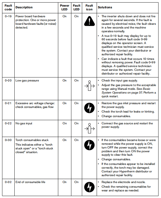
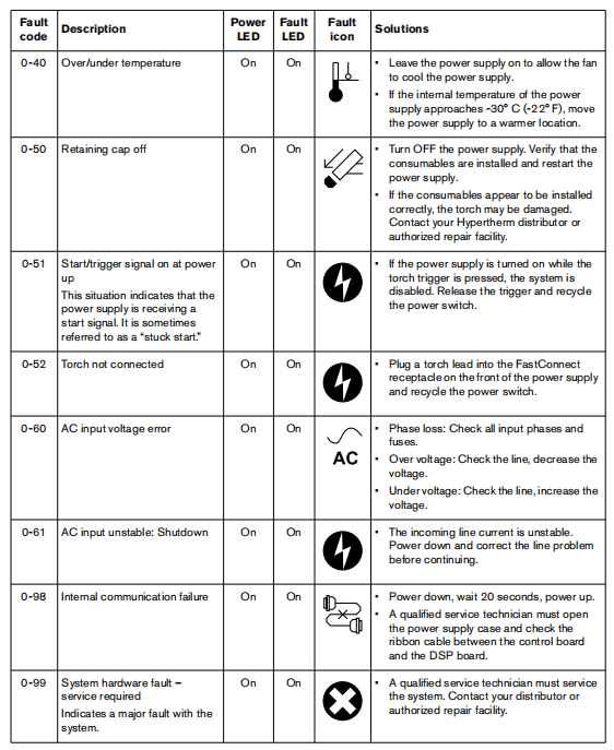
Display the service screen
You can view system information that aids troubleshooting by accessing the service screen. This screen displays recent fault codes, arc hours, the software version your system is running, and several additional details. You can also run a gas test from this screen.
For example, if a fault code displays on the status screen (in the format N-nn) while you are operating the system, you can check the service screen for an additional four-digit fault code (in the format N-nn-n). If qualified service technicians must service the system, these four-digit fault codes help them diagnose the problem.
To display the service screen, simultaneously press the automatic/manual and current/gas mode selectors forapproximately two seconds.
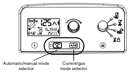
To navigate the service screen, move the field selector (*) between fields by pressing the current/gas mode selector. Theasterisk (*) indicates the selected field.
To exit the service screen, simultaneously press the automatic/manual and current/gas mode selectors. The operatorscreen displays.
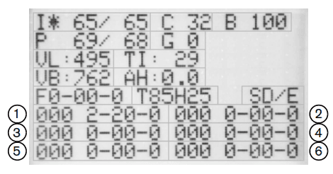
Designator
I
C
B
G
VL
TI
VB
AH
F
T
S
(callouts 1 – 6)
Description
Current set/read
LCD contrast
LCD brightness (percent)
Pressure set/read
Gas test enable (1)/disable (0)
Incoming AC line voltage
Inverter module temperature (°C)
DC bus voltage
Arc hours
Live four-digit fault code for diagnosing system errors
Torch identifier (amperage/hand (H) or machine (M)/lead length in feet)
DSP/control board software versions
Fault log of recent fault codes recorded by the system (0-00-0) and the last three digits of the arc hour count when the fault occurred (000).
Run a gas test
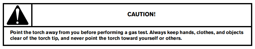
- Display the service screen by simultaneously pressingthe automatic/manual and current/gas mode selectors for approximately two seconds.
- Select the gas test field bypressing the current/gas mode selector until the asterisk (*) is next to the “G.”
- Use the adjustment knob to set the gas test field from0 to 1.
If gas does not flow, call your Hypertherm distributor or authorized Hypertherm repair facility, or call the nearest Hypertherm office listed in the front of this manual.
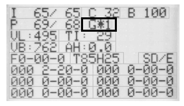
- Use the adjustment knob to set the gas test field backto 0.
- Simultaneously press the automatic/manual and current/gasmode selectors to exit the service screen.
Replace the gas filter element
- Turn OFF the power, disconnect the power cord, and make sure the gas supply is disconnected.
- Position the rear of the power supply so the removable gas filter bowl is easily accessible.
- Grasp the filter bowl with your right hand.
- Push down the thumb latch and turn the filter bowl approximately 45r degrees to the right.
- Pull the filter bowl straight down to remove. You can see the white filter element and retaining nut.
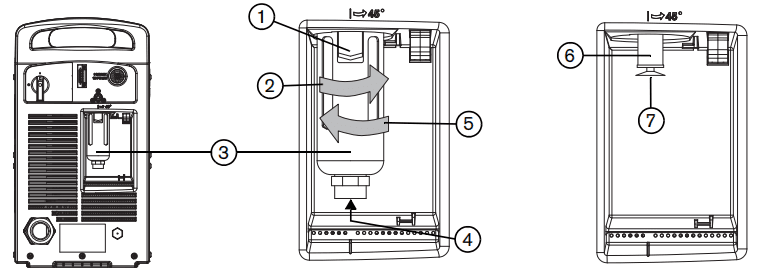
- Thumb latch
- Rotate to remove
- Filter bowl
- Helpful to lift here when replacing the filter bowl
5. Rotate to install
6. Gas filter element
7. Plastic retaining nut
6. Unscrew the plastic retaining nut that secures the filter element.
7. Replace the dirty element with a new element. Reinstall the plastic retaining nut to finger-tight only.
8. Clean the filter bowl by removing any oil or other residue.
9. Inspect the o-ring at the top of the filter bowl. If necessary, replace the o-ring with the one provided in the kit. Apply a thin film of silicone lubricant to the o-ring before installing.
10. Insert the filter bowl with the thumb latch positioned approximately 45 degrees to the right of center. This is the same orientation in which the filter bowl was pulled down and removed.
11. Vertically align the filter bowl (with metal guard) and filmly push the filter bowl up to the top of the receptacle to seat the bowl. It is helpful to lift the bowl with your left index finger under the nut on the bottom of the bowl.
12. Once the bowl is seated properly, turn the bowl 45 degrees to the left until you hear the thumb latch click into space.
13. Reconnect the gas supply hose to the power supply and check for leaks.
14. Reconnect the electrical power, and turn on the power switch.
Section 9
Parts
Use the Hypertherm kit numbers in this section to order replacement parts, consumables, and accessories for your powersupply, hand torch, and machine torch.
For instructions on installing the gas filter element in the power supply, see Replace the gas filter element on page 116.
For instructions on installing the consumables in the hand torches, see Install the hand torch consumables on page 52.
For instructions on installing the consumables in the machine torches, see Install the machine torch consumables on page 73.
Power supply part
Exterior, front
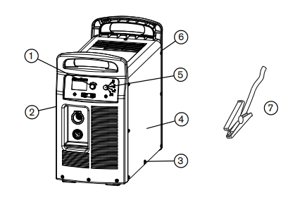
Part number
1 428143
2 228866
3 428141
4 428116
4 428247
5 428142
6 428110
6 428112
6 428111
6 428113
7
Description
Kit:adjustment knob
Kit:Powermax 105/Powermax 125 front panel
Kit:Powermax 105/Powermax 125 cover screws
Kit:Powermax 125 CSA power supply cover with labels
Kit:Powermax 125 CE power supply cover with labels
Kit:Powermax 125 CCC power supply cover with labels
Kit:Operating mode knob
Kit:Powermax 125 480V CSA rear panel
Kit:Powermax 125 600V CSA rear panel
Kit:Powermax 125 400V CE rear panel
Kit:Powermax 125 380V CCC rear panel
Work lead (See Acessory parts on page 128)
Exterior,rear
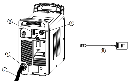
Part number
1 228193
2 428121
3 228866
3 228539
223236
223237
223239
223240
4 228884
127204
023206
023279
228350
228351
223354
223048
223356
123896
5 128650
5 128651
5 128652
Description
Kit:Powermax 125 CE power cord strain relief
Kit:Powermax 105 230-400V CE/Powermax 125 400V CE power cord
Kit:Serial interface port, internal cables, and RS-485 board
RS-485 cable, unterminated, 7.6m(25 feet)
RS-485 cable, unterminated, 15m(50 feet)
RS-485 cable, 9-pin D-sub connector for Hypertherm controls, 7.6m(25 feet)
RS-485 cable, 9-pin D-sub connector for Hypertherm controls,15m(50 feet)
Kit:Powermax 105/125 machine interface cable,internal cable with voltage divider board (CPC port)
Cover for Powermax 45/65/85/105/125 machine interface(CPC) receptacle
External machine interface cable(start,stop,arc transfer signals),7.6m(25 feet),spade connectors
External machine interface cable(start,stop,arc transfer signals),15m(50 feet),spade connectors
Kit:External machine interface cable(start,stop,arc transfer signals),7.6m(25 feet),spade connectors
Kit:External machine interface cable(start,stop,arc transfer signals),15m(50 feet),spade connectors
External machine interface cable(start,stop,arc transfer signals) for divided arc voltage, 3.0m(10 feet), D-sub connector with screws
External machine interface cable(start,stop,arc transfer signals) for divided arc voltage, 6.1m(25 feet), D-sub connector with screws
External machine interface cable(start,stop,arc transfer signals) for divided arc voltage, 7.6m(25 feet), D-sub connector with screws
External machine interface cable(start,stop,arc transfer signals) for divided arc voltage, 10.7m(35 feet), D-sub connector with screws
External machine interface cable(start,stop,arc transfer signals) for divided arc voltage, 15m(50 feet), D-sub connector with screws
Remote start pendant for machine torch, 7.6m(25 feet)
Remote start pendant for machine torch, 15m(50 feet)
Remote start pendant for machine torch, 23m(75 feet)
Interior, fan side
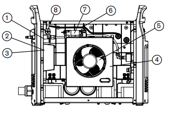
Part number
1 228685
2 428015
3 228695
4 228910
5 228881
6 228689
7 228882
8 228688
Description
Kit:Powermax 65/85/105/125 air filter assembly
Kit:AF30 air filter bowl/guard
Kit:Powermax 65/85/105/125 air filter element(inside filter bowl)
Kit:Powermax 105/Powermax 125 shroud
Kit:Powermax 105/Powermax 125 assembly
Kit:Powermax 65/85/105/125 pressure transducer
Kit:Powermax 105/Powermax 125 regulator/solenoid valve
Kit:Powermax 65/85/105/125 pressure switch
Duramax Hyamp 85° hand torch replacement parts
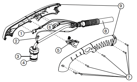
The entire hand torch and lead assembly can be replaced, or individual component parts can be replaced. Part numbers starting with 059 indicate complete torch and lead assemblies.
Part Number
059492*
059493*
059494*
1 228719
2 075696
3 428158
4 428253
5 428156
6 428162
7 428148
8 428159
8 428160
8 428161
9 428155
428260
Description
Duramax Hyamp 85° hand torch assembly with 7.6m(25 foot)lead
Duramax Hyamp 85° hand torch assembly with 15m(50 foot)lead
Duramax Hyamp 85° hand torch assembly with 23m(75 foot)lead
Kit:Duramax and Duramax Hyamp hand torch cap-sensor switch replacement
Pilot terminal screw
Kit:Duramax Hyamp 85° hand torch main body replacement
Kit:Duramax Hyamp o-ring replacement(5)
Kit:Duramax Hyamp hand torch trigger with spring replacement
Kit:Duramax Hyamp hand torch handle screws
Kit:Duramax Hyamp hand torch lead replacement, 7.6m(25 foot)
Kit:Duramax Hyamp hand torch lead replacement, 15m(50 foot)
Kit:Duramax Hyamp hand torch lead replacement, 23m(75 foot)
Kit:Duramax 85° torch handle replacement
Kit:Duramax and Duramax Hyamp torch quick disconnect repair (lead side)
* The torch assembly does not include consumables. See page 124 for a list of consumable part numbers.
Duramax Hyamp 15° hand torch replacement parts
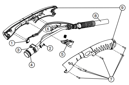
The entire hand torch and lead assembly can be replaced, or individual component parts can be replaced. Part numbers starting with 059 indicate complete torch and lead assemblies.
Part Number
059495*
059496*
059497*
1 228719
2 075696
3 428157
4 428253
5 428156
6 428162
7 428148
8 428159
8 428160
8 428161
9 428154
428260
Description
Duramax Hyamp shield 45/65 A
Duramax Hyamp shield 105/125 A
Duramax Hyamp retaining cap
Duramax Hyamp nozzle 45 A
Duramax Hyamp nozzle 65 A
Duramax Hyamp nozzle 105/125 A
Duramax Hyamp electrode
Duramax Hyamp swirl ring
* The torch assembly does not include consumables. See page 124 for a list of consumable part numbers.
Hand torch consumables
Drag cutting
Part Number
420172
420000
220977
420158
420169
220975
220971
220997
Description
Duramax Hyamp shield 45/65 A
Duramax Hyamp shield 105/125 A
Duramax Hyamp retaining cap
Duramax Hyamp nozzle 45 A
Duramax Hyamp nozzle 65 A
Duramax Hyamp nozzle 105/125 A
Duramax Hyamp electrode
Duramax Hyamp swirl ring
Gouging
Part Number
420112
220977
420001
220971
220997
Description
Duramax Hyamp gouging shield
Duramax Hyamp retaining cap
Duramax Hyamp gouging nozzle
Duramax Hyamp electrode
Duramax Hyamp swirl ring
FineCut
Part Number
420152
220977
420151
220971
420159
Description
Duramax Hyamp FineCut shield
Duramax Hyamp retaining cap
Duramax Hyamp FineCut nozzle
Duramax Hyamp electrode
Duramax Hyamp FineCut swirl ring