

Powermax 65
Powermax 85
Operator Manual
806650
Revision 1
English
Table of Contents
Section 1
Specifications
System description
Where to find information
Power supply dimensions
Component weights
Powermax65 power supply ratings
Powermax85 power supply ratings
H65/H8575″hand torch dimensions
H65s/H85s 15″ hand torch dimensions
M65/M85 ful-length machine torch dimensions
M65m/M85m mini-machine torch dimensions
Powermax65 cutting specifications
Powermax85 cutting specifications
Symbols and markings
lEC symbols
Section2
Power Supply Setup
Unpack the Powermax65 or Powermax85 system
ClaimsContents
Position the power supply
Prepare the electrical power
Install a line-disconnect switchRequirements for grounding
Power connection for the Powermax65
Single-phase power cord (not for CEmodel)
Three-phase power cord – plug installation
Power connection for the Powermax85
Single-phase power cord (not for CE model)
Single-phase power cord instalation
Three-phase power cord – plug installation
Extension cord recommendations
Extension cord specificatonsEngine-driven generator recommendations
Prepare the gas supply
Additional gas fitrationConnect the gas supply
Section 3
Torch Setup
Introduction
Consumable life
Hand torch setup
Choose the hand torch consumablesHand torch consumablesInstall the hand torch consumables
Machine torch setup
Converting an M65/M85 torch to an M65m/M85m torchMount the torchChoose the machine torch consumablesMachine torch consumablesInstall the machine torch consumablesAligning the torchConnecting an optional remote-start pendantConnecting an optional machine interface cable
Connecting the torch lead
Using the cut charts
Estimated ker-width compensation85 A shielded consumables65 A shielded consumables45 Ashielded consumablesFineCut consumables85 A unshielded consumables65 A unshielded consumables45 A unshielded consumables
Section 4
Operation
Controls and indicators
Rear controlsFront controls and LEDsStatus screen
Operating the Powemax65 or Powermax85
Connect the electrical power, gas supply and torch leadAttach the work lead to the power supplyAttach the work clamp to the workpieceTum ON the systemSet the operating mode switchCheck the indicatorsManually adjusting the gas pressureAdjusting the current (amperage)Understanding duty-cycle imitations
Using the hand torch
Operate the safety triggerHand torch cuting hintsStart a cut from the edge of the workpiecePierce a workpieceGouge a workpieceCommon hand-cutting faults
Using the machine torch
Ensure the torch and table are setup correctlyUnderstand and optimize cut qualityTo pierce a workpiece using the machine torchCommon machine-cutting faults
Section 5
Maintenance and Repair
Perform routine maintenance
Inspect the consumables
Basic troubleshooting
Fault codes and solutions
Replace the gas filter element
Section 6
Parts
Power supply parts
H65/H85 Hand torch replacement parts
H65s/H85s Hand torch replacement parts
Hand torch consumables
M65/M85 Machine torch replacement parts
M65m/M85m Machine torch replacement parts
Machine torch consumables
Accessory parts
Powermax65/85 labels
Section 1 Specifications
System description
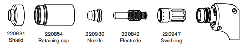
The Powermax65 and Powermax85 are highly portable, 65-amp and 85-amp,handheld and mechanized plasma cutting systems appropriate for a wide range of applications. The Powermax systems use air or nitrogen to cut electrically conductive metals, such as mild steel, stainless steel, or aluminum. Smart Sense” technology automatically adjusts the gas pressure according to cutting mode and torch lead length for optimum cutting.The Powermax65 can cut thicknesses up to 1inch (25mm) with ahandheld torch and pierce thicknesses up to 5/8 inch(16 mm). The Powermax85 can cut thicknesses up to1-1/4 inches (32 mm) and pierce thicknesses up to 3/4inch (19 mm). FastConnect provides a simple push-button torch connection to the power supply for quick torch changes.The typical handheld Powermax system includes a Duramax” series H65 or H85 hand torch with a complete set of the consumables needed for cutting (shield, retaining cap, nozzle, electrode, swirl ring), a consumables box (containing 2 spare electrodes, 2 spare nozzles, 1 gouging nozzle, and 1 gouging shield), and a work cable. Reference materials include: operator manual, quick setup card, registration card, setup DVD, and safety manual.The typical mechanized Powermax system includes a Duramax series M65 orM85 machine torch with a complete set of the consumables needed for cutting (shield, retaining cap, nozzle, electrode, swirl ring), a consumables box (containing 2 spare eledtrodes and 2 spare nozzles), work cable, and remote-start pendant. Reference materials include: operator manual, quick setup card, registration card, setup DVD, and safety manual.You can order additional styles of torches, consumables, and accessories – such as the plasma cutting guide – from any Hypertherm distributor. See Section 6, Parts for a list of spare and optional parts.Powermax65 and Powermax85 power supplies are shipped without a plug on the power cord. See Section 2 Power Supply Setup for more information.
Where to find information
System specifications such as sze, weight, detailed electrical specifications, and cut speeds can be found in this section. For information on:• Setup requirements, including power requirements,grounding, power cord configurations, extension cord requirements, and generator recommendations – see Section 2 Power Supply Setup.• Handheld and machine torch consumables, cut charts, and torch setup information – see Section 3 Torch Setup.• Information about the controls and LEDs, steps for system operation, and hints for improving cut quality – see Section 4 Operation.
• Routine maintenance and repair – see Section 5 Maintenance and Repair
• Part numbers and ordering information for accessories, consumables, and replacement parts – see Section 6, Parts.
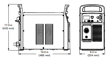
Power supply dimensions
Component weights
| 65ACSA | 65ACE | 85ACSA | 85ACE | |
| Ibs (kg) | Ibs (kg) | Ibs (kg) | Ibs (kg) | |
| Power supply | 54.1(24.5) | 47.0(213) | 59.9(27.2) | 50.4(22.8) |
| 65/85A | |
| Ibs (kg) | |
| Hand torch 25ft(7.6m) | 6.8(3.1) |
| Hand torch 50ft(15m) | 12.2(5.5) |
| Hand torch 75ft(23m) | 17.6(8.0) |
| Machine torch 25f(7.6m) | 7.6(3.4) |
| Machine torch 50ft(15m) | 13.2(6.0) |
| Machine torch 75ft (23m) | 18.8(8.5) |
| 65A | 85 A | |
| Ibs (kg) | Ibs (kg) | |
| Work lead 25 ft (7.6 m) | 2.8(1.3) | 6.8(3.1) |
| Work lead 50ft(15m) | 5.0(2.3) | 7.5(3.4) |
| Work lead 75t(23m) | 6.9(3.1) | 10.6(4.8) |
Powermax65power supply ratings
| Rated open-circuit voltage (Uo) CSA,1-phase, 3-phase CE, 3-phase | CSA296VDC CE270VDC | |
| Output characteristic | Drooping | |
| Rated output curent(l) | 20-65A | |
| Rated output voltage (U) | 139VDC | |
| Duty cycle at 40″C(104 F) (See data plate on power supply for more infomation on duty cycle) | CSA CE | 50%@65 A,230-600V,1/3PH 40%@65A200-208V,1/3PH 100%@ 46A,230-600V.1/3PH 50%@ 65 A 380/400 V.3PH 50%@ 65 A 380/400 V.3PH 100% @ 46 A.380/400V.3PH |
| Operating temperature | 14°to104°F(-10°to 40°C) | |
| Storage temperature | -13°to131°F(-25°to55°C) | |
| Power factor 200-480VCSA 1-phase 200-600VCSA3-phase 380/400V CE, 3-phase | 0.99-0.97 0.94-0.73 0.94 | |
| Roe- Short Circuit Ratio (CE models only) | U, -Volts ACrms, 3PH | Roe |
| 400VAC | 225.7 | |
| EMC classification CISPR11(CE models only)4 | Class A | |
| Input voltage (U)/ Input curent 0) at rated output (U, Max l2 max) (See Section 2 Power Supply Setup for more information) | CSA CE | 200/208/240/480V.1PH,50/60Hz 52/50/44/22A 200/208/240/480/600V,3PH,50/60Hz 32/31/27/13/13A 380/400V,3PH,50/60Hz 15.5/15A |
| Gas type | Air | Nitrogen |
| Gas quality | Clean, dry, oil-free per ISO 8573-1 Class 1.2.2 | 99.95% pure |
| Recommended gas inlet flow rate/pressure | Cuting: 400scfh,6.7 scfm (190slpm)@ 85 psi(5.9bar) Gouging:450scfh, 7.5 scfm (210 slpm) @ 70 psi (48 bar) | |
1 Defined as a plot of output voltage versus output current.
2 Equipment complies with IEC 61000-3-12provided that the short-circuit powerS_is geater than or equal to 2035 KVA at the interface point between the users supply and the public system. It is the responsibility of the installer or user of the equipment to ensure, by consultation with the distribution network operator if necessary, that the equipmentis connected only to a supply with a short-circuit power S greater than or oqual to 2035 KVA.3 Equipment complies withIEC 61000-3-11provided that the supply impedance,Zma,is 0.201 or less. It is the responsibility of the installer or user of the equipment to ensure, by consultation with the distribution network operator if necessary, that the equipment is connected only to a supply with a impedance of 0.201 or less.4 WARNING: This Class Aequipmentis notintended for usein residential locations where the electrical power is provided by the public low-voltage supply system. There may be potential difficulties in ensuring electromagnetic compatibilty in those locations, due to conducted as well as radiated disturbances.
Powermax85 power supply ratings
| Rated open-circuit voltage (Uo) CSA,1-phase, 3-phase CE, 3-phase | CSA 305VDC CE 270VDC | |
| Output characteristic | Drooping | |
| Rated output curent(l) | 25-85A | |
| Rated output voltage (U) | 143VDC | |
| Duty cycle at 40″C(104 F) (See data plate on power supply for more infomation on duty cycle) | CSA CE | 50%@65 A,230-600V,1/3PH 40%@65A200-208V,1/3PH 100%@ 46A,230-600V.1/3PH 50%@ 65 A 380/400 V.3PH 50%@ 65 A 380/400 V.3PH 100% @ 46 A.380/400V.3PH |
| Operating temperature | 14°to104°F(-10°to 40°C) | |
| Storage temperature | -13°to131°F(-25°to55°C) | |
| Power factor 200-480VCSA 1-phase 200-600VCSA3-phase 380/400V CE, 3-phase | 0.99-0.97 0.94-0.76 0.94 | |
| Roe- Short Circuit Ratio (CE models only) | U, -Volts ACrms, 3PH | Roe |
| 400VAC | 225.7 | |
| EMC classification CISPR11(CE models only)4 | Class A | |
| Input voltage (U)/ Input curent 0) at rated output (U, Max l2 max) (See Section 2 Power Supply Setup for more information) | CSA CE | 200/208/240/480V.1PH,50/60Hz 52/50/44/22A 200/208/240/480/600V,3PH,50/60Hz 32/31/27/13/13A 380/400V,3PH,50/60Hz 15.5/15A |
| Gas type | Air | Nitrogen |
| Gas quality | Clean, dry, oil-free per ISO 8573-1 Class 1.2.2 | 99.95% pure |
| Recommended gas inlet flow rate/pressure | Cuting: 400scfh,6.7 scfm (190slpm)@ 85 psi(5.9bar) Gouging:450scfh, 7.5 scfm (210 slpm) @ 70 psi (48 bar) | |
1 Defined as a plot of output voltage versus output current.
2 Equipment complies with IEC 61000-3-12provided that the short-circuit power Sis greater than or equalto 2035 KVA at the interface point between the user’s supply and the public system. It is the responsibility of the installer or user ofthe equipment to ensure, by consultation with the distribution network operator if necessary, that the equipment is connected only to a supply with a short-circuit power S greater than or equal to 2035KVA.3 Equipment complies with IEC 61000-3-11provided that the supply impedance, Zmax is O.201 or less. It is the responsibity of the installer or user of the equipment to ensure, by consultation with the distribution network operator if necessary, that the equipment is connected only to a supply with a impedance of 0.201 or less.4 WARNING: This Class Aequipmentis notintended for use in residential locations where the electrical power is provided by the public low-voltage supply system. There may be potential difficulties in ensuing electromagnetic compatibility in those locations, due to conducted as well as radiated disturbances.
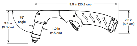
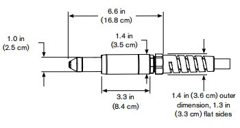
H65/H85 75°hand torch dimensions
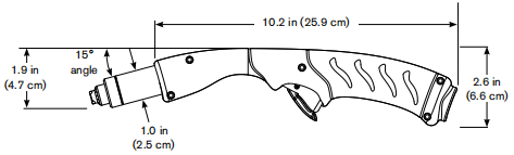
H65s/H85s 15°hand torch dimensions
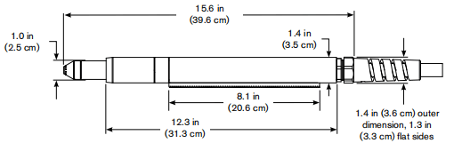
M65/M85 full-length machine torch dimensions
M65m/M85m mini machine torch dimensions
Powermax 65 Cutting Specifications
| Handheld cut capacity (material thickness) | |
| Recommended cut capacity at 20ipm (500mm/min) | 3/4in (19mm) |
| Recommended cut capacity at 10ipm (260mm/min) | 1 in(25mm) |
| Severance capacity at 5ipm(125mm/min) | 1-1/4in (32mm) |
| Pierce capacity (material thickness) | |
| Pierce capacity for handheld cutting or mechanized cutting with torch height control | 5/8in (16mm) |
| Pierce capacity for mechanized cutting without torch height control | 1/2in(12mm) |
| Maximum cut speed” (mild steel) | |
| 1/4in(6mm) | 145ipm(4000mm/min) |
| 1/2in(12mm) | 50ipm(1400mm/min) |
| 3/4in(19mm) | 24ipm(600mm/min) |
| 1in(25mm) | 12ipm(320mm/min) |
| Gouging capacity | |
| Metal removal rate on mild steel | 10.71bs/hr (4,8 kg/hr) |
| Duramax series torch weights (refer to1-5 Component weights) | |
| Duty cycle and voltage information (referto 1-6Powermax65 power supply ratings) | |
* Cut capacity speeds are not necessarily maximum speeds. They are the speeds that must be achieved to be rated at that thickness.** Maximum cut speeds are the results of Hypertherm’s laboratory testing. Actual cutting speeds may vary based on different cutting applications.
Powermax 85 Cutting Specifications
| Handheld cut capacity (material thickness) | |
| Recommended cut capacity at 20ipm (500mm/min) | 1 in (25mm) |
| Recommended cut capacity at 10ipm (260mm/min) | 1-1/4 in(32mm) |
| Severance capacity at 5ipm(125mm/min) | 1-1/2in (38mm) |
| Pierce capacity (material thickness) | |
| Pierce capacity for handheld cutting or mechanized cutting with torch height control | 3/4in (19mm) |
| Pierce capacity for mechanized cutting without torch height control | 5/8in(16mm) |
| Maximum cut speed” (mild steel) | |
| 1/4in(6mm) | 200ipm(5500mm/min) |
| 1/2in(12mm) | 70ipm(2000mm/min) |
| 3/4in(19mm) | 36ipm(900mm/min) |
| 1in(25mm) | 13ipm(330mm/min) |
| Gouging capacity | |
| Metal removal rate on mild steel | 19.5lbs/hr (8.8 kg/hr) |
| Duramax series torch weights (refer to1-5 Component weights) | |
| Duty cycle and voltage information (refer to 1-6Powermax85 power supply ratings) | |
* Cut capacity speeds are not necessarily maximum speeds. They are the speeds that must be achieved to be rated at that thickness.** Maximum cut speeds are the results of Hypertherm’s laboratory testing. Actual cutting speeds may vary based on different cutting applications.
Symbols and markings
Your Hypertherm product may have one or more of the folowing mardngs on or near the data plate. Due to differences and conficts in national regulations, not all marks are applied to every version of a product.![]()
S mark symbolThe S mark symbol indicates that the power supply and torch are suitable for operations carried out in environments with increased hazard of electrical shock per EC60974-1.![]()
CSA markHyper them products with a CSA mark meet the Unted Statesand Canadan reguations forproduct safety. The products were evaluated,tested,and coertified by CSA-lnternational. Aternatively theproduct may have a mark by one of the other Nationally Recognized Testing Laboratories (NRTUaccredited in both the United States and Canada, such as Underwriters Laboratories, Incoporated (UL) or TUV.![]()
CE markingThe CE marking signifies the manufacturer’s declaration of conformity to applicable European directives and standards. Only those versions of Hypertherm products with a CE marking located onor near the data plate have been tested for compliance with the European Low Voltage Directive and the European Electromagnetic Compatiblity (EMC)Directive. EMC filters needed to comply with the European EMC Directive are incorporated within versions of the product witha CE marking.![]()
GOST-R markCE versions of Hypertherm products that include a GOST-R mark of conformity meet the product safety and EMC requirements for export to the Russian Federation.![]()
C-Tick markCE versions of Hypertherm products with a c-Tick mark comply with the EMC regulations required for sale in Australia and New Zealand.![]()
CCCmarkThe China Compulsory Certification (CCC) mark indicates that the product has been tested and found compliant with product safety regulations required for sale in China.
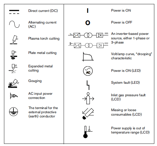
IEC symbols
The following symbols may appear on the power supply data plate, control labels, switches, LEDs, and LCD screen.
Section 2 Power Supply Setup
Unpack the Powermax65 or Powermax85 system
1. Verify that all items on your order have been received in good condition. Contact your distributor if any parts are damaged or missing2. Inspect the power supply for damage that may have occured during shipping If there is evidence of damage, refer to ‘Caims” below. All communications regarding this equipment must include the model number and the serial number located on the back of the power supply.3. Before you set up and operate this Hyperthem system, read the separate Safety and Compliance Manual included with your system for important safety infomation.
Claims
Claims for damage during shipment – If your unit was damaged during shipment, you must file a daim with the carier Hyperthem wilfurnish you with a copy of the bill of lading upon request. If you need additional assistance, call the nearest Hypertherm office listed in the front of this manual.Claims for defective or missing merchandise – If any componentis missing or defective, contact your Hyperthem distributor. If you need additional assistance, call the nearest Hypertherm office listed in the front of this manual.
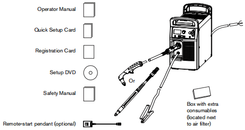
Contents
Verify the items in the box against the illustration.
Position the power supply
Locate the power supply near an appropriate power receptacle for your installation:200-480 volts (CSA1-phase),200-600volts (CSA3-phase)or 380/400 volts (3-phaseCE).The power supply has a 10-foot (3m)power cord. Allow at least 10inches (O.25 m) of space around the power supply for proper ventilation.
The power supply is not suitable for use in rain or snow.
To avoid toppling, do not set the power supply on an incline greater than 10 dogrees.
Prepare the electrical power
Hypertherm (dosignated HYP on the data plate) input current ratings are used to determine conductor sizes for power connection and installation instructions The HYP rating is determined under maximum normal operating conditions and the higher HYP input current value should be used for installation purposes.The maximum output voltage will vary based onyour input voltage and the circuits amperage.Because the current draw varies during startup slow-blow fuses arerecommended as shown in the charts below. Slow-blow fuses can withstand currents up to 1Otimes the rated value for short periods of time.
Install a line-disconnect switch
Use a line-disconnect switch for each power supply so that the operator can turn off the incoming power quickly in an emergency. Locate the switch so that itis casly accessible to the operator.Installation must be performed by a licensed electrician according to national and local codes. The interrupt level of the switch must equal or exceed the continuous rating of the fuses. In addition,the switch should:• Isolate the electrical equipment and disconnect all live conductors from the incoming supply voltage when in the OFF position.
• Have one OFF and one ON position that are clearly marked with O (OFF) and I(ON).
• Have an external operating handle that can be locked in the OFF position.
• Contain a power-operated mechanism that serves as an emergency stop.
• Have appropriate slow-blow fuses installed.See 2-6Power connection forthePowermar65 or2-8 Fower connecton for the Powermax85 for recommended fuse sizes.
Requirements for grounding
To ensure personal safety, proper operation, and to reduce electromagnetic interference (EM),the power supply must be properly grounded.• The power supply must be grounded through the power cord according to national and local electrical codes.• Single-phase service must be of the 3-wire type with a green or green/yellow wire for the protective earth ground and must comply with national and local requirements. Do not use a 2-wire service.• Three-phase service must be of the 4-wire type with a green or green/yellow wire for protective earth ground and must comply with national and local requirements.• Refer to the separate Safety and Compliance Manual included with your system for more information on grounding.
Power connection for the Powermax65
The Powemax65 CSA model is auniversal power supply that can configure itself to oporato with AC voltages from 200 to 600,1-or3-phase. The CE model is 380/400V,3-phase only. The rated output is 25-65A,139VDC.
| CSA model | Single-phase | Three-phase | ||||||
| Input voltage | 200-208 | 230-240 | 480 | 200-208 | 230-240 | 400 | 480 | 600 |
| Input current at 9.0 kw output | 52 | 44 | 22 | 32 | 27 | 15 | 13 | 13 |
| Input current during arc stretch | 74 | 74 | 38 | 45 | 45 | 27 | 23 | 23 |
| Fuse (slow-blow) | 80 | 80 | 40 | 50 | 50 | 30 | 25 | 25 |
| CEmodel | Three-phase |
| Input voltage | 380/400 |
| Input current at 9.0 kw output | 15.5/15 |
| Input current during arc stretch | 27 |
| Fuse (slow-blow) | 30 |
Single-phase power cord (not for CE model)
To operate your Powermax65 on 1-phase power, you wll need to install an appropriate power cord. Refer to 2-10 Single-phase power cord installation for instructions.
Three-phase power cord – plug installation
The Powermax65 power supplies are shipped with an 8 AWG4-wire power cord on CSA models.A2.5mm,4-wire HAR power cord is provided on CE models To operate the Powermax65, use a plug that meets national and local electricalcodes. The plug must be connected to the power cord by a licensed electrician.The procedure is similar to installing a single-phase power cord as shown in the section 2-10 Single- phase power cord installation. The figure below shows the additional wire connected to L3.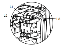
Power connection for the Powermax85
| CSA model | Single-phase | Three-phase | ||||||
| Input voltage | 200-208 | 230-240 | 480 | 200-208 | 230-240 | 400 | 480 | 600 |
| Input current at 9.0 kw output | 70 | 60 | 29 | 42 | 36 | 21 | 18 | 17 |
| Input current during arc stretch | 98 | 98 | 50 | 60 | 60 | 38 | 31 | 30 |
| Fuse (slow-blow) | 100 | 100 | 50 | 60 | 60 | 40 | 30 | 30 |
| CEmodel | Three-phase |
| Input voltage | 380/400 |
| Input current at 9.0 kw output | 20.5/20 |
| Input current during arc stretch | 38 |
| Fuse (slow-blow) | 40 |
Single-phase power cord (not for CE model)
To operate your Powermax85 on 1-phase power, you wll need to install an appropriate power cord. Refer to 2-10 Single-phase power cord installation for instructions.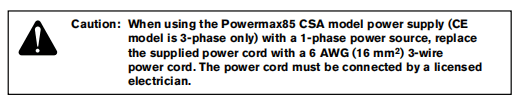
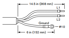
Single-phase power cord installation
Strip and prepare the power cord wires as shown below.
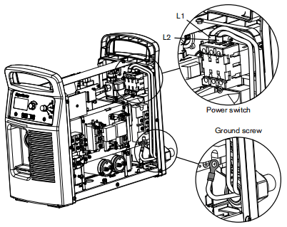
Three-phase power cord – plug installation
The Powermax85 power supplies are shipped with an 8 AWG4-wire power cord on CSA models.A4mm,4-wire HAR power cord is provided on CE models To operate the Powermax85, use a plug that meets national and local electrical codes. The plug must be connected to the power cord by a licensed electrician.The procedure is similar to installing a single-phase power cord as shown in the section 2-10 Single- phase power cord installation. The figure below shows the additional wire connected to L3.
Extension cord recommendations
Any extension cord must have an appropriate wire size for the cord length and system voltage.Use a cord that meets national and local codes.The table on the next page provides the recommended gauge sizes for various lengths and input voltages. The lengths in the tables are the length of the extension cord only; they do not include the power supply’s power cord.
Extension cord specifications
| Extension cord length | <10ft (<3m) | 10-25ft (3-7.5m) | 25-50 ft (7.5-15m) | 50-100ft (15-30m) | 100-150ft (30-45m) | |
| 65ACSA | ||||||
| Input voltage(VAC) | Phase | AwG(mm²) | AwG(mm²) | AwG(mm²) | AwG(mm²) | AwG(mm²) |
| 200-400 | 1 | 8(10) | 8(10) | 8(10) | 6(16) | 4(25) |
| 480 | 1 | 12(4) | 12(4) | 12(4) | 10(6) | 10(6) |
| 200-240 | 3 | 10(6) | 10(6) | 10(6) | 8(10) | 6(16) |
| 400/480 | 3 | 12(4) | 12(4) | 12(4) | 12(4) | 12(4) |
| 600 | 3 | 12(4) | 12(4) | 12(4) | 12(4) | 12(4) |
| 65ACE | ||||||
| Input voltage(VAC) | Phase | mm² | mm² | mm² | mm² | mm² |
| 380 | 3 | 4 | 4 | 4 | 4 | 4 |
| 400 | 3 | 4 | 4 | 4 | 4 | 4 |
| 85ACSA | ||||||
| Input voltage(VAC) | Phase | AwG(mm²) | AwG(mm²) | AwG(mm²) | AwG(mm²) | AwG(mm²) |
| 200-400 | 1 | 6(16) | 6(16) | 6(16) | 4(25) | 2(35) |
| 480 | 1 | 10(6) | 10(6) | 10(6) | 8(10) | 8(10) |
| 200-240 | 3 | 8(10) | 8(10) | 8(10) | 6(16) | 4(25) |
| 400/480 | 3 | 10(6) | 10(6) | 10(6) | 10(6) | 10(6) |
| 600 | 3 | 10(6) | 10(6) | 10(6) | 10(6) | 10(6) |
| 85ACE | ||||||
| Input voltage(VAC) | Phase | mm² | mm² | mm² | mm² | mm² |
| 380 | 3 | 6 | 6 | 6 | 6 | 6 |
| 400 | 3 | 6 | 6 | 6 | 6 | 6 |
Engine-driven generator recommendations
Generators used with the Powermax65 or Powemmax85 should satisfy the following requirements:
CSA
• 1-phase,50/60Hz,230/240VAC • 3-phase, 50/60Hz,200-600 VAC(480VAC recommended for best performance)
CE
• 3-phase,50/60Hz,380/400 VAC(400VAC recommended for best performance)
| Engine drive rating | System output current | Performance (arc stretch) |
| 20kw | 85A | Full |
| 15 kw | 70A | Limited |
| 15 kw | 65 A | Full |
| 12kw | 65 A | Limited |
| 12kw | 40A | Full |
| 8 kw | 40A | Limited |
| 8 kw | 30A | Full |
Note:Based on the generator rating, age, and condition, adjust the cutting current as needed.If a fault occurs while using a generator, turning the power switch quickly to OFF and then to ON again (sometimes called a”quick reset) may not clear the fault Instead, turn OFF the power supply and wait 30 to 45 seconds before turning ON again.
Prepare the gas supply
The gas supply can be shop-compressed or cylinder-compressed. A high-pressure regulator must be used on either type of supply and must be capable of delivering gas to the air inlet on the power supply.If the supply quality is poor, cut speeds decrease, cut quality deteriorates, cutting thickness capability decreases, and the life of the consumables shortens. For optimal performance the gas should be compliant with 1S08573-1:2010, Class1.22 (that is,it should have a maximum number of sold particulate per m³of <20,000 for particle sizes in the range of 01-05 microns,<400 for particle sizes in the range of 05-1 microns, and <10 for particle sizes in the range of 1-5 microns).The maximum water vapor dew point should be <-40° C(-40° F). The maximum oil(aerosol, liquid, and vapor) content shoud be less than O.1mg/m3.
Additional gas filtration
When site conditions introduce moisture, oil, or other contaminants into the gas line, usea3-stage coalescing fitration system, such as the Eliminzer fiter kit (part number 128647) available from Hypertherm distributors. A 3-stage filtering system works as shown below to clean contaminants from the gas supply.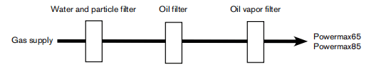
The filtering system should be installed between the gas supply and the power supply. Additional gas filtration may increase the required minimum inlet pressure.
Connect the gas supply
Connect the gas supply to the power supply using an inert-gas hose witha 3/8 inch (9.5mm) internal diameter and a 1/4 NPT quick-disconnect coupler, or a 1/4 NPTxG-1/4 BSPP (CE units) quick-disconnect coupler.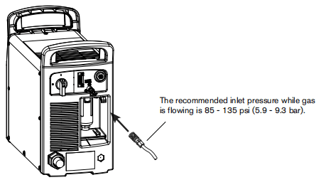
Minimum inlet pressure (while gas is flowing)
This table shows the minimum required inlet pressure when the recommended inlet pressure is not available.
| Torch lead length | |||
| 25ft (7.62m) | 50ft(15.24m) | 75 ft (22.86m) | |
| Cutting | 75 psi (5.2 bar) | 80 psi (5.5 bar) | 85 psi(5.9 bar) |
| Gouging | 60 psi (4.1 bar) | 65 psi (4.5 bar) | 70 psi (4.8 bar) |
Gas flow rates
| Cutting | 400 scfh, 6.7 scfm (190 slpm) ata minimum 85 psi (5.9 bar) |
| Gouging | 450 scfh,75 scfm (210 slpm) at a minimum 70 psi (4.8 bar) |
Section 3 Torch Setup
Introduction
Duramax” series handheld and machine torches are available for the Powermax65 and Powermax85 systems.The FastConnectw quick-dsconnect system makes iteasy to remove the torch for transport or to switch fom one torch to the other ifyour applications require the use of different torches The torches are cooled by ambient air and do not require special cooling procedures.This section explains how to setup your torch and choose the appropriate consumables for the job.
Consumable life
How often you need to change the consumables on your Powermax65 or Powermax85 will depend on a number of factors:
• The thickness of the metal being cut.
• The average length of the cut.
• Whether you are doing machine or hand cutting.
• The air quality (presence of oil, moisture, or other contaminants).
• Whether you are piercing the metal or starting cuts from the edge.
• Proper torch-to-work distance when gouging or cutting with unshielded consumables.
• Proper pierce height.
• Whether you are cutting in “continuous pilot arc” mode or normal mode. Cutting with a continuous pilot arc causes more consumable wear.Under normal conditions, the electrode will wear out first during machine cutting and the nozzle will wear out first when hand cutting.A general rule is that a set of consumables lasts approximately 2to3 hours of actual “arc on”time for hand cutting depending on these factors. For mechanized cutting, consumables shoud last about 3 to 5 hours.
You will find more information about proper cutting techniques in Section 4, Operation.
Hand Torch
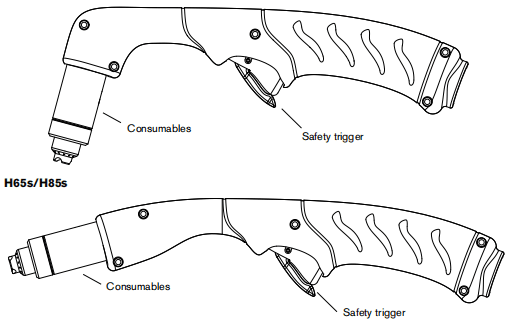
Choose the hand torch consumables
Powermax systems with the Duramax series H65,H85,H65s,orH85s torch are shipped with a full set of cutting consumables pne-installod. Hyportherm also includes spare cutting electrodes and nozzles and gouging consumables in the consumables box.
Both styles of hand torches shown above use the same consumables.
Hand torches use shielded consumables. Therefore, you can drag the torch tip along the metal
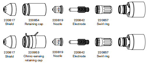
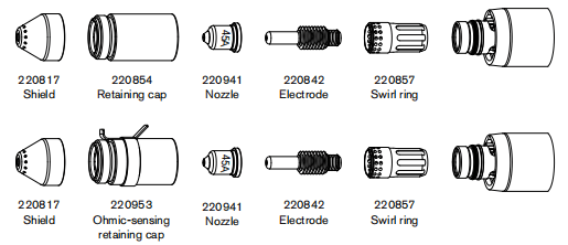
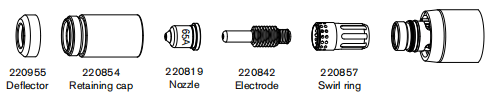
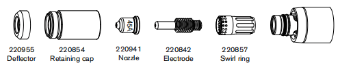
Consumables for hand cutting are shown on the next page. Notice that the retaining cap and electrode are the same for cutting, gouging, and FineCutf appications. Only the shield, nozzle, and swil ring are different.For the best cut qualty on thin materials, you may prefer to use FineCut consumables, or use a 45 A nozzle and reduce the amperage to that setting
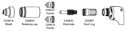
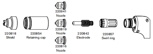
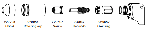
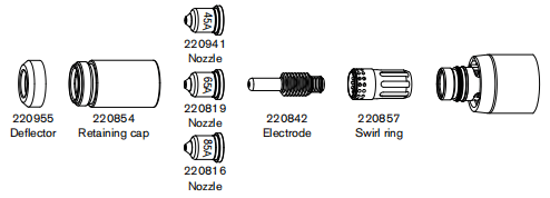
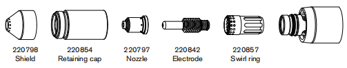
Hand torch consumables
Drag-cutting consumables: Powermax65
Drag-cutting consumables: Powermax85
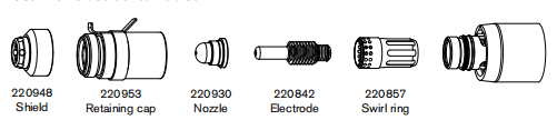
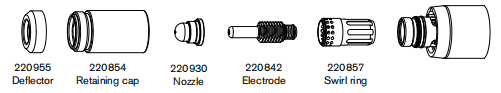
Gouging consumables
Finecut consumables
Install the hand torch consumables
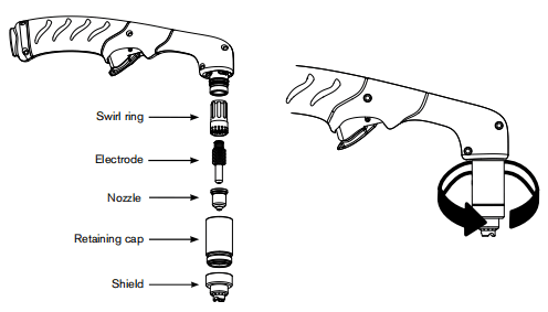
To operate the hand torch, a complete set of consumable parts must be installed: shield, retaining cap, nozzle, electrode, and swirl ring.
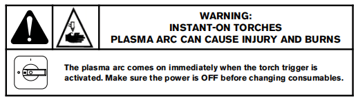
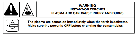
With the power switch in the OFF (O) position, install the torch consumables as shown below.
Machine torch setup
M65/M85
M65m/M85m
Before using either style of machine torch, you must:
• Mount the torch on your cutting table or other equipment.
• Choose and install the consumables.
• Align the torch.
• Attach the torch lead to the power supply.• Set up the power supply for remote starting with either the remote-start pendant or a machine interface cable.
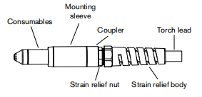
Converting an M65/M85 torch to an M65m/M85m torch
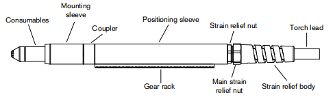
You can convert a full-length machine torch to a mini-machine torch by removing the positioning sleeve.Note: If you are converting a full-length machine torchtoa mini-machine torch and mounting the torch at the same time, skip this section and follow the instructions in 3-11 Mount the torch.
Refer to the figures in the section 3-8 Machine torch setup and follow these instructions.
Note: While disconnecting and reconnecting the torch parts, maintain the same orientation between the torch head and torch lead. Twising the torch head in relation to the torch lead can cause damage.1.Disconnect the torch lead from the power supply and remove the consumables from the torch. 2.Unscrew the strain relief body from the strain relief nut and slide the strain relief body back along the torch lead.3.Unscrew the strain relief nut from the positioning sleeve and slide the nut back albng the torch lead. 4.Unscrew the positioning sleeve from the coupler.5.Unscrew the coupler from the mounting sleeve. 6.Remove the three screws from the consumables end of the mounting sleeve and side the mounting sleeve off the front of the torch body.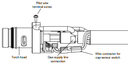
7.Disconnect the wire connector for the cap-sensor switch. 8.Usea#2 Philips screwdriver to remove the screw that secures the torch’s pilot wire to the torch body.9.Use 1/4inch and 3/8-inch wrenches,or adjustable wrenches,to loosen the nut that secures the gas suppby line to the torch lead. Set the torch body aside. 10. Slide the coupler and positioning sleeve off the front of the torch lead.11. Slide the coupler over the torch lead. 12. Reconnect the gas line to the torch lead.13. Reattach the torch’s pilot wire to the torch body using the screw. 14. Reconnect the cap-sensor switch’s wire connector.15. Slide the mounting sleeve over the front of the torch body. Align the slot on the front of the mounting sloeve (next to one of the three screw holes) with the cap-sensor plunger on the torch body. 16. Attach the mounting sleeve to the torch body using the three screws.17. Scrow the coupler into the mouning sleeve. 18. Screw the strain relief nut into the coupler.
19. Screw the strain relief body into the strain relief nut.
Mount the torch
Depending on the type of cutting table you have, you may or may not need to disassemble the torch to route it through the track and mount it. If your cuting table’s track is large enough for you to thread the torch through it without removing the torch body from the lead, do so and then attach the torch to the lifter per the manufacturer’s instructions.Note: The Duramax machine torches can be mounted on awide variety of X-Y tables, track burners, pipe bevelers, and other equpment. Install the torch per the manufacturers instructions and follow the instructions below for disassembly if necessary.If you need to disassemble and reassemble the torch,refer to the figures in the section 3-8 Machine torch setup and follow these instructions.Note::While disconnecting and reconnecting the torch parts, maintain the same orientation between the torch head and torch lead. Twisting the torch head in relation to the torch lead can cause damage.1. Disconnect the torch lead from the power supply and remove the consumables from the torch2. Unscrew the strain relief body from the strain relief nut and slide the strain relief body back along the torch lead3. Unscrew the strain relief nut from the positioning sleeve (full-ength machine torch) and slide the nut back along the torch lead.4. Unscrew the positioning sleeve from the coupler.5. Unscrew the coupler from the mounting sleeve.6. Remove the three scrows from the consumables end of the mounting sleeve and slide the mounting sleeve off the front of the torch body.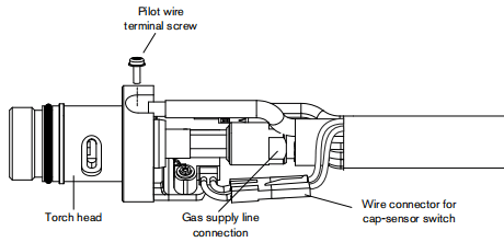
7. Disconnect the wire connector for the cap-sensor switch8.Use a#2 Philips screwdriver toremove the screw that secures the torch’s pilot wire to the torch body.9.Use 1/4-inch and 3/8-inch wrenches,or adjustable wrenches, to loosen the nut that secures the gas supply line to the torch lead Set the torch body aside.Note: Cover the end of the gas line on the torch lead with tape to keep dirt and other contaminants from getting in the gas line when you route the lead through the track.10. Slide the coupler, positioning sleeve (full-length machine torch), strain relief nut, and strain relief body off the front of the torch lead.11. If you do not need the gear rack on a full-length machine torch, side the gear track from the positioning sleeve toward tho consumables end of the sleeve12. Route the torch lead through the cutting table’s track13. Slide the strain relief body and strain relief nut over the torch lead.14. If you are mounting a full-length machine torch,slide the positioning sleeve over the torch head.15. Slide the coupler over the torch lead.16. Reconnect the gas line to the torch lead.17. Reattach the torch’s pilot wire to the torch body using the screw.18.Reconnect the cap-sensor switch’s wire connector.19. Slde the mounting sleeve over the front ofthe torch body.Align the slot on the front of the mounting sleeve (next to one of the three screw holes) with the cap-sensor plunger on the torch body.20. Attach the mounting sleeve to the torch body using the three screws.21. Screw the coupler into the mounting sleeve.22. If you are mounting a full-length machine torch, screw the positioning sleeve into the coupler.23. Reconnect the strain relef nut and strain relief body.24. Attach the torch to the lifter per the manufacturer’s instructions.
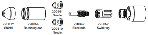
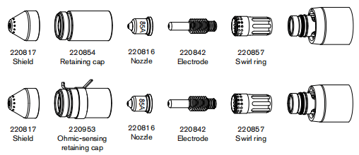
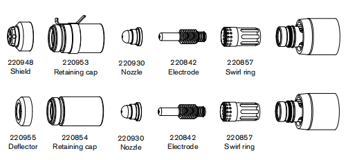
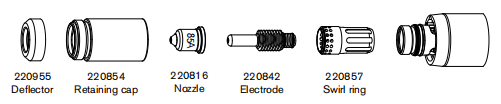
Choose the machine torch consumables
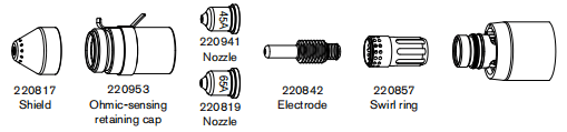
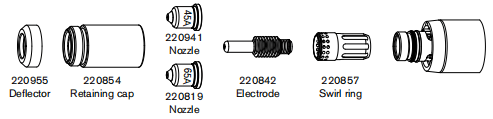
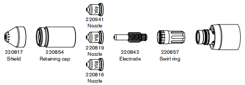
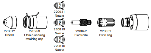
Powemax systems with the Durama M65, MB5,M65m,or M85m are shipped with a complete set of consumables. Hypertherm also includes spare electrodes and nozzles. In addition, an ohmic-sensing retaining cap is available for use with shielded consumables. With shielded consumables, the torch tip may touch the metal when cutting. With unshielded consumables, you must keep the torch a small distance, about .08 inch (2mm), away from the metal Unshielded consumables generally have a shorter life than shielded consumables.
Both styles of machine torches use the same consumables.
Machine torch consumables
Mechanized shielded consumables:Powermax65
Mechanized shielded with ohmic consumables:Powermax65
Mechanized unshielded consumables:Powermax65
Mechanized shielded consumables:Powermax85
Mechanized shielded with ohmic consumables:Powermax85
Mechanized unshielded consumables:Powermax85
Gouging consumables
Finecut shielded consumables
Finecut unshielded consumables
Install the machine torch consumables
To operate the machine torch, a complete set of consumable parts must be installed: shield, retaining cap, nozzle, electrode, and swirl ring.With the power switch in the OFF (O) position,instal tho machine torch consumables in a manner similar to the hand torch consumables. Refer to 3-7Install the hand torch consumables.
Aligning the torch
Mount the machine torch perpendicular to the workpiece in order to geta vertical cut. Use a square to align the torch at of and 9o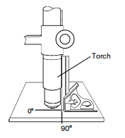
Connecting an optional remote-start pendant
Powermax65 and Powermax85 configurations with a Duramax machine torch can include an optional remote-start pendant• Part number 128650:25foot(7.6m)• Part number 128651:50foot(15m• Part number 128652:75foot(23m)Remove the receptacle cover and plug the Hypertherm remote-start pendant into the receptacle on the rear of the power supply.Note: The remote-start pendant is for use only with a machine torch. It will not operate if a handheld torch is installed.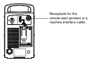
Connecting an optional machine interface cable
The Powermax65 and Powemax85 power supplies are equipped with an optional, factory installed, five-postion voltage divider that is designed to be safely connected without tools.The built-in voltage divider provides a scaled down arc voltage of 20:1,21.1:1,30:1,40:1,and 50:1 (maximum output of 18 V).An optional receptacle on the rear of the power supply provides access to the scaled down arc voltage and signals for arc transfer and plasma start.Note: The factory presets the voltage divider to 50:1. To change the voltage divider to a different setting, refer to 3-22 Seting the five-position voltage divider.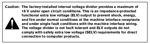
Hypertherm offers several choices of machine interface cables for the Powermax65 and Powermax85:• To use the built-in voltage divider that provides a scaled down arc voltage in addition to signals for arc transfer and plasma start:– Use part number 228350 (25t,76 m) or 228351 (60 t15 m) for wires terminated with spade connectors.Use part number 123896 (50ft,15m) for a cable terminated with a D-sub connector. (Compatible with Hypertherm’s Edge Ti and Sensor PHC products)• To use signals for arc transfer and plasma start only, use either part number 023206 (25ft,7.6 m) or part number O23279 (50ft, 15 m) These cables have spade connectors as shown below.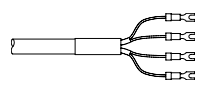
Note: The cover on the machino intorface receptacle prevents dust and moisture from damaging the receptacle when not in use. This cover should be replaced if damaged or lost (part number 127204).
See Section 6, Parts for more information.
Installation of the machine interface cable must be performed by a qualified service technician.To install a machine interface cable:1.Turn OFF the power and disconnect the power cord 2.Remove the machine interface receptacle’s cover from the rear of the power supply.3Connect the Hypertherm machine interface cable to the power supply.4. If you are using a cable with a D-sub connector on the other end, plug it into the appropriate pin connector on the torch height controller or CNC. Secure it with the screws on the D-sub conector.If you are using a cable with wires and spade connectors on the other end, terminate the machine interface cable inside the olectrical enclosure of listed and certified torch height controllers or CNC controllers to prevent unauthorized access to the connections after installation.Verify that the connections are correct and that all live parts are enclosed and protected before operating the equipment.Note: The integration of Hypertherm equipment and customer-supplied equipment including interconnecting cords and cables, if not listed and certified as a system,is subject to inspection by local authorities at the final installation site.The connector sockets for each type of signal available through the machine interface cable are shown in the figure below. The table provides details about each signal type.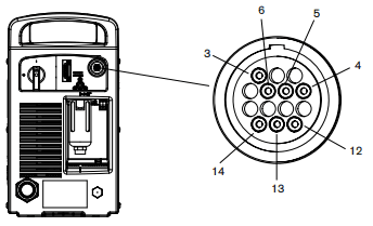
Refer to the following table when comnecting the Powemax65 or Powermax85 to a torch height controller or CNC controler with a machine interface cable.
| Signal | Type | Notes | Connector sockets | Cable wires |
| Start (start plasma) | Input | Normally open. 18VDC open circuit outage at STARTterminals. Requires dry contact closure to activate. | 3,4 | Green, Black |
| Transfer (start machine motion) | Output | Normally open. Dry contact closure when the arc transfers. 120VAC/1A maximum at the machine intertace relay or switching device (supplied by the customed). | 12,14 | Red, black |
| Ground | Ground | 13 | ||
| Voltage divider | Output | Divided arc signal of 20:1,21.1:1,30:1.40:1,50:1(provides a maximum of 18V). | 5(-),6(+) | Black (-), white (+) |
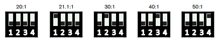
Setting the five-position voltage divider
To change the factory preset voltage dvider from 50:1 to a different setting:
1. Tun OFF the power supply and disconnect the power cord.2.Remove the power supply cover.3. Locate the voltage dvider DIP switches on the left side of the power supply.
Note: The figure below shows the default setting (50:1) with the number 4 switch up.
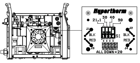
4. Set the DIP switches to one of the following settings and replace the power supply cord.
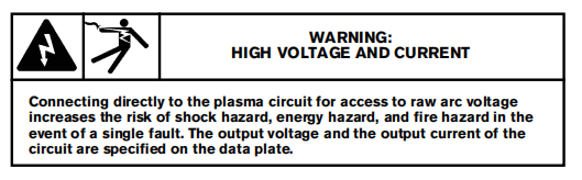
Access raw arc voltage
To access divided raw arc voltage, refer to Field Service Bulletin 807060.
Connecting the torch lead
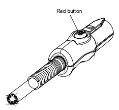
The Powermax65 and Powermax85 are equipped with FastConnect, a quick-disconnect system for connecting and disconnecting handheld and machine torch leads.When connecting or disconnecting a torch, first turn OFF the system. To connect either torch, push the connector into tho receptacle on the front of the power supply.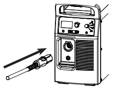
To remove the torch, press the red button on the connector and pull the connector out of the receptacle.
Using the cut charts
The following sections provide cut charts for each set of mechanized consumables A consumable diagram with part numbers precedes each set of charts. For each consumable type, there are Metric and Engish charts for mild steel, stainless steel, and aluminum.
Each chart contains the following information:
• Material Thickness – Thickness of the workpiece (metal plate being cut).
• Torch-to-Work Distance – For shielded consumables, the distance between the tip of the shield and the workpiece during cutting. For unshielded consumables,the distance between the tip of the nozzle and the workpiece during cutting.• Initial Pierce Height- Distance between the tip of the shield (shielded) or the nozzle (unshielded) and the workpiece when the torch is triggered, prior to descending to the cut height.• Pierce Delay Time – Length of time the tiggered torch remains stationary at the pierce height before the torch starts the cutting motion.• Best Quality Settings (cut speed and voltage) – Settings that provide the starting point for finding the best cut quality (best angle,least dross, best cut-surface finish). Adjust the speed for your application and table to obtain the desired result.• Production Setings (cut speed and voltage) -80% of the maximum speed ratings. These speeds result in the greatest numbor of cut parts, but not necessarily the best possible cut quality.Note: The arc voltage increases as the consumables wear and the voltage setting should be increased to maintain the correct Torch-to-Work Distance.
Each cut chart lists hot and cold air flow rates.
Hot air flow rate – Plasma is on, the system is operating at running current, and the system is in a steady state at the default system pressure automatic mode).Cold air flow rate – Plasma is off and the system is in a steady state with air flowing through the torch at the default system pressure.Note: Hypertherm collected the data under laboratory test conditions using new consumables.
Estimated kerf-width compensation
The widths in the tables below are for reference. The data are obtained with the “Best Quality” settings. Differences between installations and material composition may cause actual results to vary from those shown in the tables.
Estimated kerf-width compensation – Metric(mm)
| Process | Thickness (mm) | |||||||||
| 0.5 | 1 | 2 | 3 | 6 | 8 | 10 | 12 | 16 | 20 | |
| Mild Steel | ||||||||||
| 85A Shielded | 1.7 | 1.8 | 1.9 | 2.0 | 2.2 | 2.4 | 2.6 | |||
| 65A Shielded | 1.6 | 1.6 | 1.8 | 1.9 | 2.0 | 2.2 | 2.3 | |||
| 45A Shielded | 1.1 | 1.1 | 1.4 | 1.5 | 1.7 | |||||
| FineCut | 0.7 | 0.7 | 1.3 | 1.3 | ||||||
| 85A Unshielded | 1.7 | 1.8 | 1.9 | 2.0 | 2.1 | 2.1 | 2.3 | |||
| 65A Unshielded | 1.6 | 1.6 | 1.8 | 1.8 | 1.9 | 2.0 | ||||
| 45A Unshielded | 0.5 | 0.9 | 1.3 | 1.3 | ||||||
| Stainless Steel | ||||||||||
| 85A Shielded | 1.7 | 1.8 | 1.9 | 2.1 | 2.3 | 2.4 | 2.5 | |||
| 65A Shielded | 1.4 | 1.5 | 1.8 | 1.9 | 2.0 | 2.2 | 2.4 | |||
| 45A Shielded | 0.9 | 1.1 | 1.5 | 1.6 | 1.8 | |||||
| FineCut | 0.6 | 0.6 | 1.4 | 1.5 | ||||||
| 85A Unshielded | 1.7 | 1.7 | 1.8 | 1.9 | 2.1 | 2.2 | 2.4 | |||
| 65A Unshielded | 1.6 | 1.6 | 1.8 | 1.8 | 1.9 | 2.0 | ||||
| 45A Unshielded | 0.5 | 1.0 | 1.3 | 1.5 | 1.5 | |||||
| Aluminum | ||||||||||
| 85A Shielded | 2.0 | 1.9 | 2.0 | 2.1 | 2.2 | 2.4 | 2.6 | |||
| 65A Shielded | 1.9 | 1.9 | 1.9 | 2.0 | 2.1 | 2.3 | 2.5 | |||
| 45A Shielded | 1.5 | 1.5 | 1.6 | 1.5 | ||||||
| 85A Unshielded | 1.9 | 1.9 | 1.9 | 2.0 | 2.0 | 2.1 | 2.2 | |||
| 65A Unshielded | 1.8 | 1.8 | 1.8 | 1.8 | 1.9 | 2.0 | ||||
| 45A Unshielded | 1.6 | 1.5 | 1.4 | 1.5 | ||||||
Estimated kerf-width compens ation – English (inches)
| Process | Thickness (inches) | |||||||||
| 22GA | 18GA | 14GA | 10GA | 3/16 | 1/4 | 3/8 | 1/2 | 5/8 | 3/4 | |
| Mild Steel | ||||||||||
| 85A Shielded | 0.068 | 0.071 | 0.073 | 0.078 | 0.095 | 0.098 | 0.100. | |||
| 65A Shielded | 0.062 | 0.065 | 0.068 | 0.070 | 0.076 | 0.088 | 0.090 | 0.091 | ||
| 45A Shielded | 0.035 | 0.054 | 0.055 | 0.061 | 0.065 | 0.066 | ||||
| FineCut | 0.024 | 0.043 | 0.049 | 0.051 | ||||||
| 85A Unshielded | 0.070 | 0.073 | 0.075 | 0.0800 | 0.085 | 0.098 | ||||
| 65A Unshielded | 0.062 | 0.064 | 0.066 | 0.068 | 0.075 | 0.081 | ||||
| 45A Unshielded | 0.020 | 0.050 | 0.051 | 0.054 | 0.057 | 0.059 | ||||
| Stainless Steel | ||||||||||
| 85A Shielded | 0.068 | 0.071 | 0.073 | 0.078 | 0.095 | 0.098 | 0.100 | |||
| 65A Shielded | 0.062 | 0.065 | 0.068 | 0.070 | 0.076 | 0.088 | 0.090 | 0.091 | ||
| 45A Shielded | 0.035 | 0.054 | 0.055 | 0.061 | 0.065 | 0.066 | ||||
| FineCut | 0.024 | 0.043 | 0.049 | 0.051 | ||||||
| 85A Unshielded | 0.070 | 0.073 | 0.075 | 0.0800 | 0.085 | 0.098 | ||||
| 65A Unshielded | 0.062 | 0.064 | 0.066 | 0.068 | 0.075 | 0.081 | ||||
| 45A Unshielded | 0.020 | 0.050 | 0.051 | 0.054 | 0.057 | 0.059 | ||||
| Aluminum | ||||||||||
| 1/32 | 1/16 | 1/8 | 3/16 | 1/4 | 3/8 | 1/2 | 5/8 | 3/4 | ||
| 85A Shielded | 0.080 | 0.078 | 0.075 | 0.080 | 0.090 | 0.095 | 0.100 | |||
| 65A Shielded | 0.073 | 0.074 | 0.075 | 0.1 | 0.083 | 0.091 | 0.100 | |||
| 45A Shielded | 0.059 | 0.061 | 0.065 | 0.060 | ||||||
| 85A Unshielded | 0.075 | 0.075 | 0.075 | 0.080 | 0.082 | 0.088 | ||||
| 65A Unshielded | 0.070 | 0.070 | 0.070 | 0.070 | 0.072 | 0.079 | ||||
| 45A Unshielded | 0.062 | 0.058 | 0.057 | 0.061 | ||||||
85A shielded consumables
85A Shielded MiId Steel
| Air flow rate -slpm/scfh | |
| Hot | 190/400 |
| Cold | 235/500 |
Metric
| Material Thickness | Torch-to-Work Distance | Initial Pierce Height | Pierce Delay Time | Best Quality Settings | Production Settings | |||
| Cut Speed | Voltage | Cut Speed | Voltage | |||||
| mm | mm | mm | % | seconds | (mm/min) | Volts | (mm/min) | Volts |
| 3 | 1.5 | 3.8 | 250 | 0.1 | 6800 | 122 | 9200 | 120 |
| 4 | 0.2 | 5650 | 122 | 7300 | 122 | |||
| 6 | 0.5 | 3800 | 123 | 4400 | 125 | |||
| 8 | 2500 | 125 | 3100 | 127 | ||||
| 10 | 1680 | 127 | 2070 | 128 | ||||
| 12 | 4.5 | 300 | 0.7 | 1280 | 130 | 1600 | 130 | |
| 16 | 1.0 | 870 | 134 | 930 | 133 | |||
| 20 | 6.0 | 400 | 1.5 | 570 | 137 | 680 | 136 | |
| 25 | Edge Start | 350 | 142 | 450 | 141 | |||
| 30 | 300 | 146 | 300 | 144 | ||||
English
| Material Thickness | Torch-to-Work Distance | Initial Pierce Height | Pierce Delay Time | Best Quality Settings | Production Settings | |||
| Cut Speed | Voltage | Cut Speed | Voltage | |||||
| in | in | % | seconds | ipm | Volts | ipm | Volts | |
| 10GA | 0.06 | 0.15 | 250 | 0.0 | 250 | 122 | 336 | 121 |
| 3/16in | 0.2 | 185 | 123 | 220 | 123 | |||
| 1/4in | 0.5 | 130 | 123 | 160 | 126 | |||
| 3/8in | 70 | 126 | 86 | 127 | ||||
| 1/2in | 0.18 | 300 | 45 | 131 | 56 | 131 | ||
| 5/8in | 1.0 | 35 | 134 | 37 | 133 | |||
| 3/4in | 0.24 | 400 | 1.5 | 24 | 136 | 29 | 135 | |
| 7/8in | Edge Start | 19 | 139 | 22 | 138 | |||
| 1in | 13 | 142 | 17 | 141 | ||||
| 1-1/8in | 9 | 145 | 13 | 143 | ||||
| 1-1/4in | 7 | 148 | 10 | 146 | ||||
85A Shielded Stainless Steel
| Air flow rate -slpm/scfh | |
| Hot | 190/400 |
| Cold | 235/500 |
Metric
| Material Thickness | Torch-to-Work Distance | Initial Pierce Height | Pierce Delay Time | Best Quality Settings | Production Settings | |||
| Cut Speed | Voltage | Cut Speed | Voltage | |||||
| mm | mm | mm | % | seconds | (mm/min) | Volts | (mm/min) | Volts |
| 3 | 1.5 | 3.8 | 250 | 0.1 | 7500 | 122 | 9200 | 120 |
| 4 | 0.2 | 6100 | 122 | 7500 | 120 | |||
| 6 | 0.5 | 3700 | 122 | 4600 | 122 | |||
| 8 | 2450 | 125 | 3050 | 124 | ||||
| 10 | 4.5 | 300 | 1550 | 127 | 1900 | 126 | ||
| 12 | 0.7 | 1100 | 131 | 1400 | 130 | |||
| 16 | 1.0 | 700 | 135 | 760 | 134 | |||
| 20 | Edge Start | 480 | 138 | 570 | 137 | |||
| 25 | 300 | 143 | 370 | 141 | ||||
English
| Material Thickness | Torch-to-Work Distance | Initial Pierce Height | Pierce Delay Time | Best Quality Settings | Production Settings | |||
| Cut Speed | Voltage | Cut Speed | Voltage | |||||
| in | in | % | seconds | ipm | Volts | ipm | Volts | |
| 10GA | 0.06 | 0.15 | 250 | 0.2 | 275 | 122 | 336 | 120 |
| 3/16in | 200 | 122 | 240 | 121 | ||||
| 1/4in | 0.5 | 130 | 122 | 164 | 122 | |||
| 3/8in | 65 | 126 | 80 | 125 | ||||
| 1/2in | 0.18 | 300 | 36 | 132 | 47 | 131 | ||
| 5/8in | 1.0 | 28 | 135 | 30 | 134 | |||
| 3/4in | Edge Start | 20 | 137 | 24 | 136 | |||
| 7/8in | 16 | 140 | 19 | 139 | ||||
| 1in | 11 | 143 | 14 | 141 | ||||
85A Shielded Aluminum
| Air flow rate -slpm/scfh | |
| Hot | 190/400 |
| Cold | 235/500 |
Metric
| Material Thickness | Torch-to-Work Distance | Initial Pierce Height | Pierce Delay Time | Best Quality Settings | Production Settings | |||
| Cut Speed | Voltage | Cut Speed | Voltage | |||||
| mm | mm | mm | % | seconds | (mm/min) | Volts | (mm/min) | Volts |
| 3 | 1.5 | 3.8 | 250 | 0.1 | 8000 | 122 | 9400 | 121 |
| 4 | 0.2 | 6500 | 123 | 8000 | 123 | |||
| 6 | 0.5 | 3800 | 126 | 4900 | 125 | |||
| 8 | 2650 | 130 | 3470 | 129 | ||||
| 10 | 4.5 | 300 | 1920 | 132 | 2900 | 131 | ||
| 12 | 0.7 | 1450 | 134 | 1930 | 133 | |||
| 16 | 1.0 | 950 | 136 | 1200 | 137 | |||
| 20 | Edge Start | 600 | 143 | 880 | 141 | |||
| 25 | 380 | 146 | 540 | 144 | ||||
English
| Material Thickness | Torch-to-Work Distance | Initial Pierce Height | Pierce Delay Time | Best Quality Settings | Production Settings | |||
| Cut Speed | Voltage | Cut Speed | Voltage | |||||
| in | in | % | seconds | ipm | Volts | ipm | Volts | |
| 3/16in | 0.06 | 0.15 | 250 | 0.2 | 300 | 122 | 360 | 121 |
| 1/4in | 0.5 | 130 | 127 | 172 | 127 | |||
| 3/8in | 80 | 132 | 107 | 131 | ||||
| 1/2in | 0.18 | 300 | 50 | 135 | 68 | 133 | ||
| 5/8in | 1.0 | 38 | 139 | 48 | 137 | |||
| 3/4in | Edge Start | 25 | 142 | 37 | 140 | |||
| 7/8in | 20 | 144 | 29 | 142 | ||||
| 1in | 14 | 146 | 20 | 144 | ||||
65A shielded consumables
65A Shielded MiId Steel
| Air flow rate -slpm/scfh | |
| Hot | 160/340 |
| Cold | 220/470 |
Metric
| Material Thickness | Torch-to-Work Distance | Initial Pierce Height | Pierce Delay Time | Best Quality Settings | Production Settings | |||
| Cut Speed | Voltage | Cut Speed | Voltage | |||||
| mm | mm | mm | % | seconds | (mm/min) | Volts | (mm/min) | Volts |
| 2 | 1.5 | 3.8 | 250 | 0.1 | 6050 | 124 | 7000 | 121 |
| 3 | 0.2 | 5200 | 125 | 6100 | 123 | |||
| 4 | 0.5 | 4250 | 125 | 5100 | 124 | |||
| 6 | 2550 | 127 | 3240 | 127 | ||||
| 8 | 1700 | 129 | 2230 | 128 | ||||
| 10 | 4.5 | 300 | 0.7 | 1100 | 131 | 1550 | 129 | |
| 12 | 1.2 | 850 | 134 | 1140 | 131 | |||
| 16 | 6.0 | 400 | 2.0 | 560 | 138 | 650 | 136 | |
| 20 | Edge Start | 350 | 142 | 450 | 142 | |||
| 25 | 210 | 145 | 270 | 145 | ||||
English
| Material Thickness | Torch-to-Work Distance | Initial Pierce Height | Pierce Delay Time | Best Quality Settings | Production Settings | |||
| Cut Speed | Voltage | Cut Speed | Voltage | |||||
| in | in | % | seconds | ipm | Volts | ipm | Volts | |
| 16GA | 0.06 | 0.15 | 250 | 0.1 | 260 | 123 | 294 | 121 |
| 10GA | 190 | 125 | 224 | 123 | ||||
| 3/16in | 0.2 | 140 | 126 | 168 | 125 | |||
| 1/4in | 0.5 | 90 | 127 | 116 | 127 | |||
| 3/8in | 0.7 | 45 | 130 | 62 | 129 | |||
| 1/2in | 0.18 | 300 | 1.2 | 30 | 135 | 40 | 132 | |
| 5/8in | 0.24 | 400 | 2.0 | 23 | 138 | 26 | 136 | |
| 3/4in | Edge Start | 15 | 141 | 19 | 141 | |||
| 7/8in | 12 | 143 | 14 | 143 | ||||
| 1in | 8 | 145 | 10 | 145 | ||||
65A Shielded Stainless Steel
| Air flow rate -slpm/scfh | |
| Hot | 160/340 |
| Cold | 220/470 |
Metric
| Material Thickness | Torch-to-Work Distance | Initial Pierce Height | Pierce Delay Time | Best Quality Settings | Production Settings | |||
| Cut Speed | Voltage | Cut Speed | Voltage | |||||
| mm | mm | mm | % | seconds | (mm/min) | Volts | (mm/min) | Volts |
| 2 | 1.5 | 3.8 | 250 | 0.1 | 8100 | 125 | 10000 | 121 |
| 3 | 0.2 | 6700 | 125 | 8260 | 123 | |||
| 4 | 0.5 | 5200 | 125 | 6150 | 124 | |||
| 6 | 2450 | 126 | 2850 | 126 | ||||
| 8 | 0.7 | 1500 | 129 | 1860 | 129 | |||
| 10 | 4.5 | 300 | 960 | 132 | 1250 | 132 | ||
| 12 | 1.2 | 750 | 135 | 960 | 134 | |||
| 16 | Edge Start | 500 | 139 | 500 | 139 | |||
| 20 | 300 | 143 | 370 | 143 | ||||
English
| Material Thickness | Torch-to-Work Distance | Initial Pierce Height | Pierce Delay Time | Best Quality Settings | Production Settings | |||
| Cut Speed | Voltage | Cut Speed | Voltage | |||||
| in | in | % | seconds | ipm | Volts | ipm | Volts | |
| 16GA | 0.06 | 0.15 | 250 | 0.1 | 345 | 124 | 426 | 121 |
| 10GA | 240 | 125 | 296 | 123 | ||||
| 3/16in | 0.2 | 155 | 126 | 168 | 125 | |||
| 1/4in | 0.5 | 88 | 126 | 96 | 126 | |||
| 3/8in | 0.7 | 40 | 131 | 52 | 131 | |||
| 1/2in | 0.18 | 300 | 1.2 | 26 | 136 | 32 | 135 | |
| 5/8in | Edge Start | 20 | 139 | 20 | 139 | |||
| 3/4in | 14 | 142 | 15 | 142 | ||||
65A Shielded Aluminum
| Air flow rate -slpm/scfh | |
| Hot | 160/340 |
| Cold | 220/470 |
Metric
| Material Thickness | Torch-to-Work Distance | Initial Pierce Height | Pierce Delay Time | Best Quality Settings | Production Settings | |||
| Cut Speed | Voltage | Cut Speed | Voltage | |||||
| mm | mm | mm | % | seconds | (mm/min) | Volts | (mm/min) | Volts |
| 2 | 1.5 | 3.8 | 250 | 0.1 | 8800 | 121 | 10300 | 122 |
| 3 | 0.2 | 7400 | 124 | 8800 | 124 | |||
| 4 | 0.5 | 6000 | 126 | 7350 | 125 | |||
| 6 | 3200 | 130 | 4400 | 128 | ||||
| 8 | 0.7 | 1950 | 133 | 2750 | 130 | |||
| 10 | 4.5 | 300 | 1200 | 136 | 1650 | 132 | ||
| 12 | 1.2 | 1000 | 138 | 1330 | 136 | |||
| 16 | Edge Start | 650 | 143 | 800 | 141 | |||
| 20 | 380 | 147 | 560 | 145 | ||||
English
| Material Thickness | Torch-to-Work Distance | Initial Pierce Height | Pierce Delay Time | Best Quality Settings | Production Settings | |||
| Cut Speed | Voltage | Cut Speed | Voltage | |||||
| in | in | % | seconds | ipm | Volts | ipm | Volts | |
| 1/16in | 0.06 | 0.15 | 250 | 0.1 | 365 | 121 | 428 | 121 |
| 1/8in | 280 | 124 | 336 | 124 | ||||
| 1/4in | 0.5 | 105 | 131 | 152 | 128 | |||
| 3/8in | 0.7 | 50 | 135 | 68 | 131 | |||
| 1/2in | 0.18 | 300 | 1.2 | 35 | 139 | 48 | 138 | |
| 5/8in | Edge Start | 26 | 143 | 32 | 141 | |||
| 3/4in | 16 | 146 | 24 | 144 | ||||
45A shielded consumables
45A Shielded MiId Steel
| Air flow rate -slpm/scfh | |
| Hot | 150/310 |
| Cold | 210/450 |
Metric
| Material Thickness | Torch-to-Work Distance | Initial Pierce Height | Pierce Delay Time | Best Quality Settings | Production Settings | |||
| Cut Speed | Voltage | Cut Speed | Voltage | |||||
| mm | mm | mm | % | seconds | (mm/min) | Volts | (mm/min) | Volts |
| 0.5 | 1.5 | 3.8 | 250 | 0.0 | 9000 | 128 | 12500 | 126 |
| 1 | 9000 | 128 | 10800 | 128 | ||||
| 1.5 | 0.1 | 9000 | 130 | 10200 | 129 | |||
| 2 | 0.3 | 6600 | 130 | 7800 | 129 | |||
| 3 | 0.4 | 3850 | 133 | 4900 | 131 | |||
| 4 | 2200 | 134 | 3560 | 131 | ||||
| 6 | 0.5 | 1350 | 137 | 2050 | 132 | |||
English
| Material Thickness | Torch-to-Work Distance | Initial Pierce Height | Pierce Delay Time | Best Quality Settings | Production Settings | |||
| Cut Speed | Voltage | Cut Speed | Voltage | |||||
| in | in | % | seconds | ipm | Volts | ipm | Volts | |
| 26GA | 0.02 | 0.08 | 400 | 0.0 | 350 | 128 | 500 | 128 |
| 22GA | 350 | 128 | 450 | 128 | ||||
| 18GA | 0.1 | 350 | 129 | 400 | 128 | |||
| 16GA | 350 | 130 | 400 | 129 | ||||
| 14GA | 0.06 | 0.15 | 250 | 0.2 | 270 | 130 | 320 | 129 |
| 12GA | 0.4 | 190 | 133 | 216 | 131 | |||
| 10GA | 100 | 134 | 164 | 131 | ||||
| 3/16in | 0.5 | 70 | 135 | 108 | 132 | |||
| 1/4in | 0.6 | 48 | 137 | 73 | 132 | |||
45A Shielded Stainless Steel
| Air flow rate -slpm/scfh | |
| Hot | 150/310 |
| Cold | 210/450 |
Metric
| Material Thickness | Torch-to-Work Distance | Initial Pierce Height | Pierce Delay Time | Best Quality Settings | Production Settings | |||
| Cut Speed | Voltage | Cut Speed | Voltage | |||||
| mm | mm | mm | % | seconds | (mm/min) | Volts | (mm/min) | Volts |
| 0.5 | 1.5 | 3.8 | 250 | 0.0 | 9000 | 130 | 12500 | 129 |
| 1 | 9000 | 130 | 10800 | 130 | ||||
| 1.5 | 0.1 | 9000 | 130 | 10200 | 130 | |||
| 2 | 0.3 | 6000 | 132 | 8660 | 131 | |||
| 3 | 0.4 | 3100 | 132 | 4400 | 132 | |||
| 4 | 2000 | 134 | 2600 | 134 | ||||
| 6 | 0.5 | 900 | 140 | 1020 | 139 | |||
English
| Material Thickness | Torch-to-Work Distance | Initial Pierce Height | Pierce Delay Time | Best Quality Settings | Production Settings | |||
| Cut Speed | Voltage | Cut Speed | Voltage | |||||
| in | in | % | seconds | ipm | Volts | ipm | Volts | |
| 26GA | 0.02 | 0.08 | 400 | 0.0 | 350 | 130 | 500 | 129 |
| 22GA | 350 | 130 | 450 | 129 | ||||
| 18GA | 0.1 | 350 | 130 | 400 | 130 | |||
| 16GA | 350 | 130 | 400 | 130 | ||||
| 14GA | 0.06 | 0.15 | 250 | 0.2 | 250 | 132 | 320 | 131 |
| 12GA | 0.4 | 140 | 132 | 216 | 131 | |||
| 10GA | 100 | 133 | 134 | 134 | ||||
| 3/16in | 0.5 | 52 | 135 | 58 | 135 | |||
| 1/4in | 0.6 | 30 | 141 | 32 | 140 | |||
45A Shielded Aluminum
| Air flow rate -slpm/scfh | |
| Hot | 150/310 |
| Cold | 210/450 |
Metric
| Material Thickness | Torch-to-Work Distance | Initial Pierce Height | Pierce Delay Time | Best Quality Settings | Production Settings | |||
| Cut Speed | Voltage | Cut Speed | Voltage | |||||
| mm | mm | mm | % | seconds | (mm/min) | Volts | (mm/min) | Volts |
| 1 | 1.5 | 3.8 | 250 | 0.0 | 8250 | 136 | 11000 | 136 |
| 2 | 0.1 | 6600 | 136 | 9200 | 135 | |||
| 3 | 0.2 | 3100 | 139 | 6250 | 134 | |||
| 4 | 0.4 | 2200 | 141 | 4850 | 134 | |||
| 6 | 0.5 | 1500 | 142 | 2800 | 137 | |||
English
| Material Thickness | Torch-to-Work Distance | Initial Pierce Height | Pierce Delay Time | Best Quality Settings | Production Settings | |||
| Cut Speed | Voltage | Cut Speed | Voltage | |||||
| in | in | % | seconds | ipm | Volts | ipm | Volts | |
| 1/32in | 0.06 | 0.15 | 250 | 0.0 | 325 | 136 | 450 | 136 |
| 1/16in | 0.1 | 325 | 136 | 400 | 136 | |||
| 3/32in | 0.2 | 200 | 136 | 328 | 134 | |||
| 1/8in | 0.4 | 100 | 140 | 224 | 134 | |||
| 1/4in | 0.5 | 54 | 142 | 96 | 137 | |||
Finecut consumables
Note: The cut charts in this section apply to both shielded and unshielded consumables.
Finecut Mild Steel
| Air flow rate -slpm/scfh | |
| Hot | 155/330 |
| Cold | 215/460 |
Metric
| Material Thickness | Amps | Torch-to-Work Distance | Initial Pierce Height | Pierce Delay Time | Best Quality Settings | ||
| Cut Speed | Voltage | ||||||
| mm | A | mm | mm | % | seconds | (mm/min) | Volts |
| 0.5 | 40 | 1.5 | 3.8 | 250 | 0.0 | 8250 | 78 |
| 0.6 | 8250 | 78 | |||||
| 0.8 | 0.1 | 8250 | 78 | ||||
| 1 | 45 | 0.2 | 8250 | 78 | |||
| 1.5 | 0.4 | 6400 | 78 | ||||
| 2 | 5250 | 82 | |||||
| 3 | 0.5 | 2750 | 83 | ||||
| 4 | 0.6 | 1900 | 84 | ||||
English
| Material Thickness | Amps | Torch-to-Work Distance | Initial Pierce Height | Pierce Delay Time | Best Quality Settings | ||
| Cut Speed | Voltage | ||||||
| A | in | in | % | seconds | ipm | Volts | |
| 26GA | 40 | 0.06 | 0.15 | 250 | 0.0 | 325 | 78 |
| 24GA | 325 | 78 | |||||
| 22GA | 0.1 | 352 | 78 | ||||
| 20GA | 325 | 78 | |||||
| 18GA | 45 | 0.2 | 325 | 78 | |||
| 16GA | 0.4 | 250 | 78 | ||||
| 14GA | 220 | 82 | |||||
| 12GA | 0.5 | 120 | 83 | ||||
| 10GA | 95 | 84 | |||||
Finecut Stainless Steel
| Air flow rate -slpm/scfh | |
| Hot | 155/330 |
| Cold | 215/460 |
Metric
| Material Thickness | Amps | Torch-to-Work Distance | Initial Pierce Height | Pierce Delay Time | Best Quality Settings | ||
| Cut Speed | Voltage | ||||||
| mm | A | mm | mm | % | seconds | (mm/min) | Volts |
| 0.5 | 40 | 1.5 | 3.8 | 250 | 0.0 | 8250 | 68 |
| 0.6 | 8250 | 68 | |||||
| 0.8 | 0.1 | 8250 | 68 | ||||
| 1 | 45 | 0.2 | 8250 | 68 | |||
| 1.5 | 0.4 | 6150 | 70 | ||||
| 2 | 4800 | 71 | |||||
| 3 | 0.5 | 2550 | 81 | ||||
| 4 | 0.6 | 1050 | 84 | ||||
English
| Material Thickness | Amps | Torch-to-Work Distance | Initial Pierce Height | Pierce Delay Time | Best Quality Settings | ||
| Cut Speed | Voltage | ||||||
| A | in | in | % | seconds | ipm | Volts | |
| 26GA | 40 | 0.06 | 0.15 | 250 | 0.0 | 325 | 68 |
| 24GA | 325 | 68 | |||||
| 22GA | 0.1 | 352 | 68 | ||||
| 20GA | 325 | 68 | |||||
| 18GA | 45 | 0.2 | 325 | 68 | |||
| 16GA | 0.4 | 240 | 70 | ||||
| 14GA | 200 | 70 | |||||
| 12GA | 0.5 | 120 | 80 | ||||
| 10GA | 75 | 83 | |||||
85A unshielded consumables
85A unshielded Mild Steel
| Air flow rate -slpm/scfh | |
| Hot | 190/400 |
| Cold | 235/500 |
Metric
| Material Thickness | Torch-to-Work Distance | Initial Pierce Height | Pierce Delay Time | Best Quality Settings | Production Settings | |||
| Cut Speed | Voltage | Cut Speed | Voltage | |||||
| mm | mm | mm | % | seconds | (mm/min) | Volts | (mm/min) | Volts |
| 2 | 2.0 | 5.0 | 250 | 0.0 | 7150 | 117 | 10400 | 116 |
| 3 | 0.1 | 6240 | 118 | 9000 | 117 | |||
| 4 | 0.2 | 5250 | 118 | 7200 | 117 | |||
| 6 | 0.5 | 3450 | 120 | 4400 | 119 | |||
| 8 | 2400 | 121 | 3100 | 121 | ||||
| 10 | 1560 | 123 | 2070 | 122 | ||||
| 12 | 6.0 | 300 | 0.7 | 1200 | 126 | 1600 | 124 | |
| 16 | Edge Start | 820 | 132 | 930 | 128 | |||
| 20 | 540 | 137 | 640 | 132 | ||||
| 25 | 320 | 143 | 400 | 137 | ||||
English
| Material Thickness | Torch-to-Work Distance | Initial Pierce Height | Pierce Delay Time | Best Quality Settings | Production Settings | |||
| Cut Speed | Voltage | Cut Speed | Voltage | |||||
| in | in | % | seconds | ipm | Volts | ipm | Volts | |
| 14GA | 0.08 | 0.20 | 250 | 0.1 | 280 | 117 | 416 | 116 |
| 10GA | 0.2 | 230 | 118 | 328 | 117 | |||
| 3/16in | 175 | 119 | 220 | 118 | ||||
| 1/4in | 0.5 | 125 | 120 | 160 | 119 | |||
| 3/8in | 65 | 122 | 88 | 122 | ||||
| 1/2in | 0.24 | 300 | 0.6 | 42 | 127 | 56 | 125 | |
| 5/8in | Edge Start | 33 | 131 | 37 | 128 | |||
| 3/4in | 23 | 136 | 27 | 131 | ||||
| 7/8in | 18 | 140 | 21 | 134 | ||||
| 1in | 12 | 144 | 15 | 138 | ||||
85A unshielded Stainless Steel
| Air flow rate -slpm/scfh | |
| Hot | 190/400 |
| Cold | 235/500 |
Metric
| Material Thickness | Torch-to-Work Distance | Initial Pierce Height | Pierce Delay Time | Best Quality Settings | Production Settings | |||
| Cut Speed | Voltage | Cut Speed | Voltage | |||||
| mm | mm | mm | % | seconds | (mm/min) | Volts | (mm/min) | Volts |
| 2 | 2.0 | 5.0 | 250 | 0.1 | 8550 | 117 | 10400 | 116 |
| 3 | 7000 | 118 | 9000 | 117 | ||||
| 4 | 0.2 | 5600 | 118 | 7200 | 117 | |||
| 6 | 0.5 | 3400 | 120 | 4400 | 119 | |||
| 8 | 2250 | 121 | 3100 | 121 | ||||
| 10 | 6.0 | 300 | 0.5 | 1430 | 123 | 2070 | 122 | |
| 12 | 0.7 | 1000 | 129 | 1600 | 124 | |||
| 16 | Edge Start | 650 | 134 | 730 | 133 | |||
| 20 | 360 | 138 | 570 | 137 | ||||
English
| Material Thickness | Torch-to-Work Distance | Initial Pierce Height | Pierce Delay Time | Best Quality Settings | Production Settings | |||
| Cut Speed | Voltage | Cut Speed | Voltage | |||||
| in | in | % | seconds | ipm | Volts | ipm | Volts | |
| 14GA | 0.08 | 0.20 | 250 | 0.1 | 280 | 117 | 416 | 116 |
| 10GA | 0.2 | 230 | 118 | 328 | 117 | |||
| 3/16in | 175 | 119 | 220 | 118 | ||||
| 1/4in | 0.5 | 125 | 120 | 160 | 119 | |||
| 3/8in | 65 | 122 | 88 | 123 | ||||
| 1/2in | 0.24 | 300 | 0.6 | 35 | 131 | 46 | 129 | |
| 5/8in | Edge Start | 26 | 134 | 29 | 133 | |||
| 3/4in | 17 | 137 | 24 | 136 | ||||
85A unshielded Aluminum
| Air flow rate -slpm/scfh | |
| Hot | 190/400 |
| Cold | 235/500 |
Metric
| Material Thickness | Torch-to-Work Distance | Initial Pierce Height | Pierce Delay Time | Best Quality Settings | Production Settings | |||
| Cut Speed | Voltage | Cut Speed | Voltage | |||||
| mm | mm | mm | % | seconds | (mm/min) | Volts | (mm/min) | Volts |
| 2 | 2.0 | 5.0 | 250 | 0.1 | 8700 | 118 | 10400 | 116 |
| 3 | 7350 | 120 | 9000 | 117 | ||||
| 4 | 0.2 | 5600 | 118 | 7200 | 117 | |||
| 6 | 0.5 | 3400 | 120 | 4400 | 119 | |||
| 8 | 2250 | 121 | 3100 | 121 | ||||
| 10 | 6.0 | 300 | 0.5 | 1430 | 123 | 2070 | 122 | |
| 12 | 0.7 | 1300 | 133 | 1600 | 130 | |||
| 16 | Edge Start | 840 | 139 | 1130 | 134 | |||
| 20 | 470 | 144 | 700 | 138 | ||||
English
| Material Thickness | Torch-to-Work Distance | Initial Pierce Height | Pierce Delay Time | Best Quality Settings | Production Settings | |||
| Cut Speed | Voltage | Cut Speed | Voltage | |||||
| in | in | % | seconds | ipm | Volts | ipm | Volts | |
| 1/8in | 0.08 | 0.20 | 250 | 0.2 | 280 | 120 | 368 | 119 |
| 3/16in | 200 | 122 | 328 | 117 | ||||
| 1/4in | 0.5 | 110 | 126 | 220 | 118 | |||
| 3/8in | 75 | 127 | 160 | 119 | ||||
| 1/2in | 0.24 | 300 | 0.6 | 45 | 135 | 62 | 123 | |
| 5/8in | Edge Start | 34 | 139 | 45 | 134 | |||
| 3/4in | 22 | 143 | 32 | 137 | ||||
65A unshielded consumables
65A unshielded Mild Steel
| Air flow rate -slpm/scfh | |
| Hot | 160/340 |
| Cold | 220/470 |
Metric
| Material Thickness | Torch-to-Work Distance | Initial Pierce Height | Pierce Delay Time | Best Quality Settings | Production Settings | |||
| Cut Speed | Voltage | Cut Speed | Voltage | |||||
| mm | mm | mm | % | seconds | (mm/min) | Volts | (mm/min) | Volts |
| 2 | 2.0 | 5.0 | 250 | 0.1 | 6050 | 118 | 10400 | 116 |
| 3 | 7350 | 120 | 9000 | 117 | ||||
| 4 | 0.2 | 5600 | 118 | 7200 | 117 | |||
| 6 | 0.5 | 3400 | 120 | 4400 | 119 | |||
| 8 | 2250 | 121 | 3100 | 121 | ||||
| 10 | 6.0 | 300 | 0.5 | 1430 | 123 | 2070 | 122 | |
| 12 | 0.7 | 1300 | 129 | 1140 | 124 | |||
| 16 | Edge Start | 500 | 134 | 650 | 129 | |||
| 20 | 280 | 138 | 400 | 133 | ||||
English
| Material Thickness | Torch-to-Work Distance | Initial Pierce Height | Pierce Delay Time | Best Quality Settings | Production Settings | |||
| Cut Speed | Voltage | Cut Speed | Voltage | |||||
| in | in | % | seconds | ipm | Volts | ipm | Volts | |
| 16GA | 0.08 | 0.20 | 250 | 0.1 | 255 | 120 | 368 | 119 |
| 14GA | 190 | 122 | 328 | 117 | ||||
| 3/16in | 0.2 | 110 | 126 | 220 | 118 | |||
| 1/4in | 0.5 | 75 | 127 | 160 | 119 | |||
| 3/8in | 0.24 | 300 | 0.7 | 40 | 135 | 62 | 123 | |
| 1/2in | Edge Start | 27 | 130 | 40 | 125 | |||
| 5/8in | 20 | 134 | 26 | 129 | ||||
| 3/4in | 13 | 137 | 18 | 132 | ||||
65A unshielded Stainless Steel
| Air flow rate -slpm/scfh | |
| Hot | 160/340 |
| Cold | 220/470 |
Metric
| Material Thickness | Torch-to-Work Distance | Initial Pierce Height | Pierce Delay Time | Best Quality Settings | Production Settings | |||
| Cut Speed | Voltage | Cut Speed | Voltage | |||||
| mm | mm | mm | % | seconds | (mm/min) | Volts | (mm/min) | Volts |
| 2 | 2.0 | 5.0 | 250 | 0.1 | 7950 | 118 | 10400 | 116 |
| 3 | 6600 | 120 | 9000 | 117 | ||||
| 4 | 0.2 | 5600 | 118 | 7200 | 117 | |||
| 6 | 0.5 | 3400 | 120 | 4400 | 119 | |||
| 8 | 2250 | 121 | 3100 | 121 | ||||
| 10 | 6.0 | 300 | 0.7 | 1430 | 123 | 2070 | 122 | |
| 12 | 0.7 | 920 | 129 | 1140 | 124 | |||
| 16 | Edge Start | 710 | 134 | 650 | 127 | |||
| 20 | 430 | 138 | 400 | 133 | ||||
English
| Material Thickness | Torch-to-Work Distance | Initial Pierce Height | Pierce Delay Time | Best Quality Settings | Production Settings | |||
| Cut Speed | Voltage | Cut Speed | Voltage | |||||
| in | in | % | seconds | ipm | Volts | ipm | Volts | |
| 16GA | 0.08 | 0.20 | 250 | 0.1 | 340 | 116 | 437 | 115 |
| 10GA | 235 | 118 | 304 | 118 | ||||
| 3/16in | 0.2 | 150 | 120 | 220 | 120 | |||
| 1/4in | 0.5 | 75 | 121 | 160 | 121 | |||
| 3/8in | 0.24 | 300 | 0.7 | 38 | 125 | 52 | 122 | |
| 1/2in | Edge Start | 25 | 132 | 32 | 129 | |||
| 5/8in | 17 | 135 | 20 | 133 | ||||
65A unshielded Aluminum
| Air flow rate -slpm/scfh | |
| Hot | 160/340 |
| Cold | 220/470 |
Metric
| Material Thickness | Torch-to-Work Distance | Initial Pierce Height | Pierce Delay Time | Best Quality Settings | Production Settings | |||
| Cut Speed | Voltage | Cut Speed | Voltage | |||||
| mm | mm | mm | % | seconds | (mm/min) | Volts | (mm/min) | Volts |
| 2 | 2.0 | 5.0 | 250 | 0.1 | 7750 | 118 | 11300 | 116 |
| 3 | 0.2 | 6550 | 120 | 9000 | 117 | |||
| 4 | 0.5 | 5600 | 118 | 7200 | 117 | |||
| 6 | 3400 | 120 | 4400 | 119 | ||||
| 8 | 0.7 | 2250 | 121 | 3100 | 121 | |||
| 10 | 6.0 | 300 | 0.7 | 1100 | 133 | 1640 | 129 | |
| 12 | Edge Start | 900 | 135 | 1250 | 133 | |||
| 16 | 600 | 139 | 700 | 136 | ||||
English
| Material Thickness | Torch-to-Work Distance | Initial Pierce Height | Pierce Delay Time | Best Quality Settings | Production Settings | |||
| Cut Speed | Voltage | Cut Speed | Voltage | |||||
| in | in | % | seconds | ipm | Volts | ipm | Volts | |
| 1/16in | 0.08 | 0.20 | 250 | 0.1 | 340 | 116 | 437 | 115 |
| 1/8in | 235 | 118 | 304 | 118 | ||||
| 3/16in | 150 | 120 | 220 | 120 | ||||
| 1/4in | 0.5 | 75 | 121 | 160 | 121 | |||
| 3/8in | 0.24 | 300 | 0.7 | 38 | 125 | 52 | 128 | |
| 1/2in | Edge Start | 25 | 132 | 32 | 134 | |||
| 5/8in | 17 | 135 | 20 | 136 | ||||
45A unshielded consumables
45A unshielded Mild Steel
| Air flow rate -slpm/scfh | |
| Hot | 147/310 |
| Cold | 210/450 |
Metric
| Material Thickness | Torch-to-Work Distance | Initial Pierce Height | Pierce Delay Time | Best Quality Settings | Production Settings | |||
| Cut Speed | Voltage | Cut Speed | Voltage | |||||
| mm | mm | mm | % | seconds | (mm/min) | Volts | (mm/min) | Volts |
| 0.5 | 1.5 | 3.8 | 250 | 0.0 | 9000 | 120 | 12500 | 120 |
| 1 | 9000 | 120 | 10800 | 121 | ||||
| 1.5 | 0.1 | 7700 | 120 | 10200 | 121 | |||
| 2 | 0.3 | 6150 | 119 | 7800 | 122 | |||
| 3 | 0.4 | 3950 | 121 | 4900 | 123 | |||
| 4 | 2350 | 123 | 3560 | 124 | ||||
| 6 | 0.5 | 1400 | 126 | 2050 | 124 | |||
English
| Material Thickness | Torch-to-Work Distance | Initial Pierce Height | Pierce Delay Time | Best Quality Settings | Production Settings | |||
| Cut Speed | Voltage | Cut Speed | Voltage | |||||
| in | in | % | seconds | ipm | Volts | ipm | Volts | |
| 26GA | 0.06 | 0.15 | 250 | 0.0 | 350 | 120 | 437 | 120 |
| 22GA | 350 | 120 | 304 | 120 | ||||
| 18GA | 0.1 | 350 | 119 | 220 | 121 | |||
| 16GA | 300 | 121 | 160 | 121 | ||||
| 14GA | 0.2 | 250 | 125 | 52 | 128 | |||
| 12GA | 0.4 | 200 | 132 | 216 | 134 | |||
| 10GA | 100 | 123 | 164 | 124 | ||||
| 3/16in | 0.5 | 85 | 122 | 108 | 124 | |||
| 1/4in | 0.6 | 48 | 127 | 73 | 124 | |||
45A unshielded Stainless Steel
| Air flow rate -slpm/scfh | |
| Hot | 147/310 |
| Cold | 210/450 |
Metric
| Material Thickness | Torch-to-Work Distance | Initial Pierce Height | Pierce Delay Time | Best Quality Settings | Production Settings | |||
| Cut Speed | Voltage | Cut Speed | Voltage | |||||
| mm | mm | mm | % | seconds | (mm/min) | Volts | (mm/min) | Volts |
| 0.5 | 1.5 | 3.8 | 250 | 0.0 | 9000 | 121 | 12500 | 119 |
| 1 | 9000 | 121 | 10800 | 119 | ||||
| 1.5 | 0.1 | 9000 | 121 | 10200 | 120 | |||
| 2 | 0.3 | 6000 | 122 | 9600 | 120 | |||
| 3 | 0.4 | 3250 | 123 | 4750 | 120 | |||
| 4 | 1900 | 128 | 3000 | 122 | ||||
| 6 | 0.5 | 700 | 130 | 1450 | 124 | |||
English
| Material Thickness | Torch-to-Work Distance | Initial Pierce Height | Pierce Delay Time | Best Quality Settings | Production Settings | |||
| Cut Speed | Voltage | Cut Speed | Voltage | |||||
| in | in | % | seconds | ipm | Volts | ipm | Volts | |
| 26GA | 0.02 | 0.08 | 400 | 0.0 | 350 | 120 | 437 | 120 |
| 22GA | 350 | 120 | 304 | 120 | ||||
| 18GA | 0.1 | 350 | 119 | 220 | 121 | |||
| 16GA | 300 | 121 | 160 | 121 | ||||
| 14GA | 0.06 | 0.15 | 250 | 0.2 | 250 | 125 | 52 | 128 |
| 12GA | 0.4 | 200 | 132 | 216 | 134 | |||
| 10GA | 100 | 125 | 140 | 121 | ||||
| 3/16in | 0.5 | 42 | 130 | 88 | 123 | |||
| 1/4in | 0.6 | 25 | 131 | 48 | 124 | |||
45A unshielded Aluminum
| Air flow rate -slpm/scfh | |
| Hot | 147/310 |
| Cold | 210/450 |
Metric
| Material Thickness | Torch-to-Work Distance | Initial Pierce Height | Pierce Delay Time | Best Quality Settings | Production Settings | |||
| Cut Speed | Voltage | Cut Speed | Voltage | |||||
| mm | mm | mm | % | seconds | (mm/min) | Volts | (mm/min) | Volts |
| 1 | 1.5 | 3.8 | 250 | 0.0 | 7400 | 126 | 12500 | 121 |
| 2 | 0.1 | 4400 | 127 | 10800 | 123 | |||
| 3 | 0.2 | 2800 | 129 | 6250 | 125 | |||
| 4 | 0.4 | 2100 | 131 | 4700 | 126 | |||
| 6 | 0.5 | 1050 | 139 | 2250 | 127 | |||
English
| Material Thickness | Torch-to-Work Distance | Initial Pierce Height | Pierce Delay Time | Best Quality Settings | Production Settings | |||
| Cut Speed | Voltage | Cut Speed | Voltage | |||||
| in | in | % | seconds | ipm | Volts | ipm | Volts | |
| 1/32in | 0.06 | 0.15 | 250 | 0.0 | 325 | 126 | 450 | 121 |
| 1/16in | 0.1 | 200 | 126 | 400 | 122 | |||
| 3/32in | 0.2 | 150 | 127 | 328 | 124 | |||
| 1/8in | 0.4 | 100 | 130 | 224 | 125 | |||
| 1/4in | 0.5 | 36 | 136 | 72 | 127 | |||
Section 4 Operation
Controls and indicators
The Powermax65 and Powemax85 power supplies have the following: ON/OFF switch, adjustment knob, automatic/manual pressure setting mode selector, curent gas selector, operating mode switch, indicator LEDs, and a status screen.
Rear controls
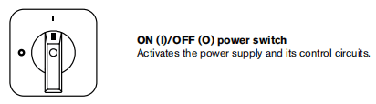
Front controls and LEDs
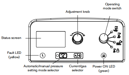

Faut LED (yellow)
When luminated, this LEDindicates that thereisafaut with the power supply.For infomation about these fault conditions and how to correct them, see Section 5, Maintenance and Repair.![]()
Power ON LED (green)
When luminated, this LEDindicates that the power switch has been settol(ON) and that the safety interlocks are satisfied. When blinking. the power supply has a fault.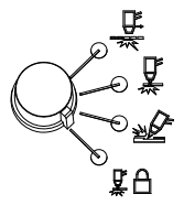
Operating mode switch
The operating mode switch can be set in one off our positions.
• Continuous pilot arc. Cuts expanded metalor grate.
• Non-continuous pilot arc. Cuts or pierces metal plate. This is the standard setting for normal drag-cutting.
• Gouge. Gouges metal plate.
• Torch lock. Same as the non-continuous pilot arc mode except the torch is locked in the ON position when you release the trigger during a cut.

Automatic/manual pressure seting mode selector
The selector switches between automatic and manual mode. In automatic mode the power supply automatically sets the gas pressure based upon the torch type and lead length and the adjustment knob sets only the amperage. In manual mode, the adustment nob sets either the gas pressure or the amperage. This LED is illuminated in manual mode.Note: Manual mode should be used by experienced users who need to optimize the gas setting (override the automatic gas setting) for a specific cutting application.When you switch from manual mode to automatic mode, the power supply automatically sets the gas pressure and the amperage setting is unchanged.When you switch from automatic mode to manual mode, the power supply remembers the previous manual gas pressure setting and the amperage setting is unchanged.When you reset the power, the powor supply remembers the previous mode, gas pressure, and amperage settings.![]()
English
Current/gas selector
When in manual mode, this selector toggles between amperage and gas pressurefor manual adjustments using the adjustment knob.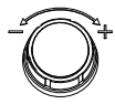
Adjustment knob
This knob adjusts the amperage. When operating in manual mode, this knob can also adjust the gas pressure, overriding the automatic setting for optimized applications.
Status screen
The status screen shows system status and fault infomation.
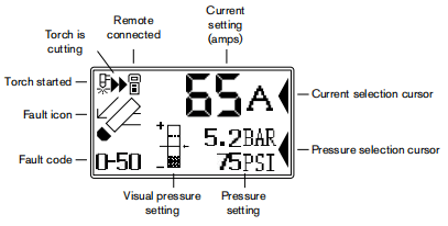
Gas pressure indicators
In manual mode, the gas pressure is displayed in bar and psi The gas pressure bar is also a visual indicator of the gas presure.![]()
Gas pressure bar
When the arrow is centered in the vertical bar (the reference pressure of the automatic pressure setting) the gas pressureis set to the preset (factory-defined) value. If the pressure is higher than the preset value, the arrow appears above the mid-point of the bar.If the pressure is lower than the preset value, the arrow appears below the mid-point of the bar.Note:In automatic mode, the power supply adjusts the pressure to the preset value.You can use manual mode to adjust the pressure to satisfy the needs of a particular cutting job. Refer to 4-13 Manually adjusting the gas pressure.
System status icons
The screen displays icons to indicate the system’s status.

Torch started
Indicates that the torch has received a start signal and has initiatod a pilot arc.

English
Torch is cutting
Indicates that the cutting anc has transferred to the metal and the torch is cutting.

Remote control
Indicates that a remote control is controling the power supply. All local controls are disabled.
Fault codes
When a power supply or torch fault occurs, the system displays a fault code in the lower-left corner of the status screen and displays a coresponding faulticon above the.code. The first digit is always zero. The other two digits identify the problem Refer to Section 5, Maintenance and Repair.Note: Only one fault code is displayed. If more than one fault occurs at the same time, only the fault code with the highest priority is displayed.
Fault icons
The fault icons that appear on the left side of the status screen are described below. A fault code also appears to identify the fault. Refer to Section 5, Maintenance and Repair.
Warning
The system continues to run.

Fault
The system stops cutting- If you can not correct the problem and restart the system,contact your distributor or Hyperthern Technical Service.
Error
The system requires service. Contact your distributor or Hypertherm Technical Service

Torch cap sensor
Indicates that the consumables are loose, improperly installed,or missing. Turn OFF the power, properly install the consumables, and turn ON the system again to reset the power supply.
Temperature
Indicates that the temporature of the power supply power modulo is outside the acceptable operating range.
Gas
Indicates that the gas is disconnected from the rear of the power supply or there is a problem with the gas supply.
English

Internal Serial Communications Interface
Indicates a problem with the SCl communications between the control board and the DSP board.
Operating the Powermax65 or Powermax85
Follow the steps below to begin cutting or gouging with the Powemax65 or Powermax85.
Connect the electrical power, gas supply, and torch lead
For infomation on connecting the proper power cord with plug to the power supply,refer to Section 2, Power Supply Setup.Plug in the power cord and connect the gas supply line. For more information about the electrical requinements and the gas supply requirements of the Powermax65 and Powermax85, see Section 2, Power Supply Setup. To connect the torch, push the FastConnect connector into the receptacle on tho front of the power supply You will attach the work lead in the next section.
Attach the work lead to the power supply
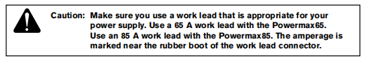
1.Insert the work lead connector into the receptacle on the front of the power supply.
Note:The receptacle is keyed. Align the key on the work lead connector with the opening at the top of the receptade on the power supply.
2.Push the work lead connector all the way into the receptacle on the power supply and turn clockewise, approximately 1/4turn, until the connector is fully seated against the stop in order to achieve an optimal electrical connection.
Attach the work clamp to the workpiece
The work damp must be connected to the workpiece while youare cutting If you are using the Powermax65 or Powemmax85 with a cuting table,you can connect the work lead directly to the table instead of attaching the work damp tothe workpiece. See your table manufacturer’s instructions.
Note the following:
• Ensure that the work clamp and the workpiece make good metal-to-metal contact. Remove rust, dirt, paint, coatings and other debris to ensure the power supply makes proper contact with the workpiece.
• For the best cut quality, attach the work clamp as close as possible to the area being cut.
• Do not attach the work clamp to the portion of the workpiece to be cut away.
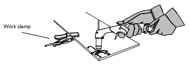
Turn ON the system
Set the ON/OFF switch to the ON (I) position.
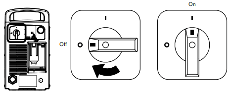
Set the operating mode switch
Use the operating mode switch to select the type of work you want to perform.
In automatic gas mode, Smart Sense technology automatically adjusts the gas pressure according to the selected cutting mode and torch lead length for optimum cutting.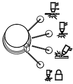
For cutting expanded metal, grates, metal containing holes, or any job that requires a continuous pilot arc. Using this mode to cut standard metal plate reduces consumable life.For gouging metal. (Note: Using this mode while cutting results in poor cut quality)
Locks the torch in the ON (fire) position. With this option selected, press the tigger to fire the torch. You can then release the trigger while continuing to cut. Press the trigger again to stop the arc. The arc also stops if you lose transfer.
For cutting or piercing metal. This is the standard setting for normal drag-cutting.
Check the indicators
Verify the following:
• The green power ON LED on the front of the power supply is illuminated.
• The Fault LED is not illuminated.
• No error icons appear in the status screen.
If a fault icon appears in the status screen, or the FaultLED is illuminated, or the power ON LED is blinking. correct the fault condition before continuing. See Section 5, Maintenance and Repair for more infomation.
Manually adjusting the gas pressure
For normal operations the power supply automatically adusts the gas pressure If you need to adjust the gas pressure for a specific application you can uso manual mode to do so.Note: Manual mode should be used by experienced users who need to optimize the gas setting (overide the automatic gas setting) for a specific cutting applicaton.When you switch from manual mode to automatic mode, the power supply automatically sets the gas pressure and the amperage setting is unchanged. When you switch from automatic mode to manual mode, the power supply remembers the previous manual gas pressure setting and the amperage setting is unchanged.When you reset the power, the power supply remembers the previous mode, gas pressure, and amperage settings.
To adjust the pressure:
1.Press the automatic/manual pressure setting mode selector so that the LED next to the selector illuminates. Refer to the diagram in 4-3 Front controls and LEDs.2. Press the current/gas selector until the selection cursor is opposite the gas pressure setting in the status screen.3. Turn the adjustment knob to adjust the gas pressure to the desired level. Watch the arrow in the pressure bar as you adjust the pressure.
Adjusting the current (amperage)
Turn the adjustment knob to adjust the curent for your particular cutting application.
If the system is in manual mode, do the following to adjust the amperage.
1. Press the current/gas selector until the selection cursoris opposite the amperage seting in the status screen.
2.Turn the adustment knob to change the amperage.
3. If you wish to exit manual mode, press the automatic/manual pressure setting mode selector. The LED goes off.
Note: When you exit manual mode, the gas pressure resets to the factory-optimized value.When you switch between manual mode and automatic mode, the power supply retains the amperage setting. When you reset the power the power supply returns to the previous mode (automatic mode or manual mode) and remembers the previous amperage setting.
Understanding duty-cycle limitations
The duty cycle is the amount of time, in minutes, that a plasma arc can remain on within a 10-minute period when operating at an ambient temperature of 104°F(40°C).
With a Powermax65:
• At 65 A the arc can remain onfor 5 minutes out of 10 minutes without causing the unit to overheat (50% duty cycle)
• At59 A,the arc can remain on for 6 minutes out of 10(60%)
• At46 A,the arc can remain on for 10 minutes out of 10(100%).
With a Powermax85:
• At 85 A,thearc can remain on for 6minutes out of 10minutes without causing the unit to overheat (60% duty cycle)• At74A,the arc can remain on for 8 minutes out of 10(80%)
• At 66 A the arc can remain onfor 10minutes out of 1o(100%).
If the duty cycle is exceeded, the power supply overheats,the tomperature faulticon appears in the status screen, the arc shuts of, and the cooing fan continues to run You cannot resume cutting until the temperature fault icon disappears and the fault LED goes off.
Using the hand torch
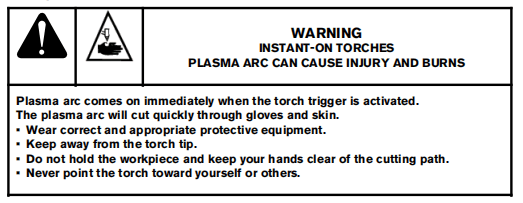
Operate the safety trigger
The hand torches are equipped with a safety trigger to prevent accidental frings. When you are ready to use the torch, flip the trigger’s safety cover forward (toward the torch head) and press the red torch trigger as show below.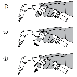
Hand torch cutting hints
• Drag the torch tip lightly along the workpiece to maintain a steady cut.
• While cutting, make sure that sparks exit from the bottom of the workpiece. The sparks shoud lag sightly behind the torch as you cut (15-30 angle from vertical).• If sparks spray up from the workpiece, move the torch more slowly, or set the output current higher.With either the 75-degree or 15-degree hand torch, hold the torch nozzle perpendicular to the workpiece so that the nozzle is ata 90″ angle tothe cutting surface. Observe the cutting arc as the torch cuts.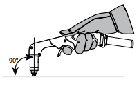
If you fire the torch unnecessarily, you will shorten the life of the nozzle and electrode.
• Pulling, or dragging the torch along the cut is easier than pushing it.
• For straight-line cuts use a straight edge as aguide. To cut circles, use atemplate or a radius cutter attachment (a circle cutting guide). See Section 6, Parts for part numbers for the Hypertherm plasma cutting guides for cutting circles and making bevel cuts.
Start a cut from the edge of the workpiece

1. With the work clamp attached to the workpiece, hold the torch nozzleperpendicular (90) to the edge of the workpiece.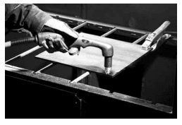
2. Press the torch’s trigger to startthe arc. Pause at the edge until the arc hascut completely through the workpiece.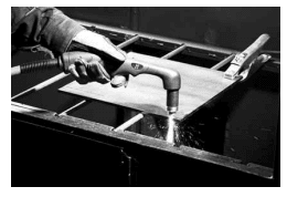
3.Drag the torchtip lightly across the workpiece to procood with the cut.Maintain a steady, even pace.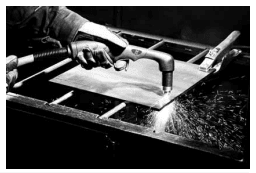
Pierce a workpiece

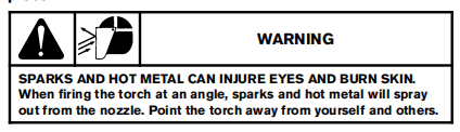
1. With the work clamp attached to the workpiece, hold the torch at an approximate 30angle to the workpiece with the torch tip within 1/16 inch(1.5 mm) of the workpiece before fring the torch.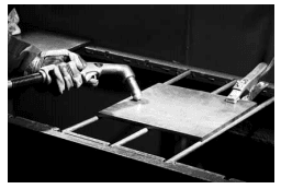
2.Fire the torch while still at an angle to the workpiece. Slowly rotate the torch to a perpendicular (90°) position.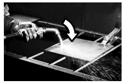
3. Hold the torch in place while continuing to press the trigger. When sparks exit below the workpiece, the arc has pierced the material.
Gouge a workpiece

1. Hold the torch so that the torch tip is within 1/16inch (1.5 mm) from the workpiece before firing the torch.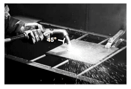
2.Hold the torch at a45″ angle to the workpiece with a small gap between the torch tip and the workpiece. Press the trigger to obtain a pilot arc. Transfer the arc to the work piece.
3.Maintain an approximate 45angle to the workpiece as you feed into the gouge. Pushthe plasma arc in the direction of the gouge you want to create. Keep a small distancebetween the torch tip and the molten metal to avoid reducing consumable life ordamaging the torch.Changing the torch’s angle changes the dimensions of the gouge.
Gouge profile
You can vary the gouge profile by varying the speed ofthe torch over the workpiece, varying the torch-to-work standoff distance, varying the angle of the torch to the workpiece, and varying the current output of the power supply.
Typical Gouge Profilefor 65A
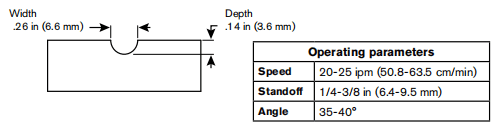
Typical Gouge Profile for 85A
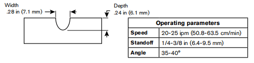
Varying the gouge profle
The following actions have the stated offects on the gouge profile:
• Increasing the speed of the torch wil decrease width and decrease depth.
• Decreasing the speed of the torch wil increase width and increase depth.
• Increasing the standoff of the torch will increase width and decrease depth.
• Decreasing the standoff of the torch will decrease width and increase depth.
• Increasing the angle of the torch (more vertical) will decrease width and increase depth.• Decreasing the angle of the torch (ess vertical) will increase width and decrease depth.
• Increasing the currentof the power supply will increase width and increase depth.
• Decreasing the current of the power supply will decrease width and decrease depth.
Common hand-cutting faults
The torch does not cut completely through the workpiece. The causes can be:
• The cut speed is too fast.
• The consumables are worn.
• The metal being cut is too thick for the selected amperage.
• Gouging consumables are installed instead of drag-cuting consumables
• The work clamp is not attached properly to the workpiece.
• The gas pressure or gas flow rate is too low.
Cut quality is poor. The causes can be:
• The metal being cut is too thick for the amperage.
• The wrong consumables are being used (gouging consumables are installed instead of drag-cutting consumables, for example).
• You are moving the torch too quickly or too slowly.
The arc sputters and consumables lifeis shorter than expected. The cause can be:
• Moisture in the gas supply.
• Incorrect gas pressure.
• Consumables incorrectly installed.
Using the machine torch
Since the Powema with a machine torch can be used with a wide variety of cutting tables, track bumers, pipe bevelers, and so on,you will need to refer to the manufacturer’s instructions for specifics on operating the machine torch in your confguration However, the information in the following sections will help you optimize cut quality and maximize consumable life.
Ensure the torch and table are set up correctly
• Use a square to align the torch at right angles to the workpiece in two dimensions.
• The torch may travel more smoothly if you clean, check and “tune”the cutting table’s rails and drive system. Unsteady machine motion can cause a regular, wavy pattern on the cut surface.• Ensure that the torch does not touch the workpiece during cuting. Contact with the workpiece can damage the shield and nozzle and affect the cut surface.
Understand and optimize cut quality
There are several factors to consider in cut quality:
• Cut angle – The degree of angularity of the cut edge.
• Dross – The molten material that solidifies on the top or bottom of the workpiece.
• Straightness of the cut surface – The cut surface can be concave or convex.
The following sections explain how those factors can affect cut quality.
Cut or bevel angle
• A positive cut angle, or bevel, results when more material is removed from the top of the cut than from the bottom.
• A negative cut angle results when more materal is removed from the bottom of the cut.
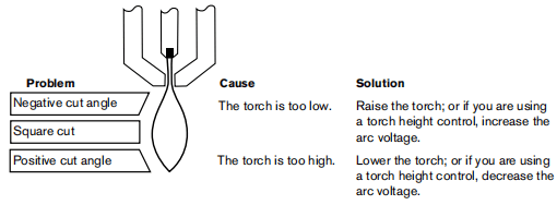
Note: The squarest cut angle will be on the rightside with respect to the forward motion of the torch. The left side will always have some degree of bevel.To determine whether a cut-angle problem is being caused by the plasma system or the drive system, make a test cut and measure the angle ofeach side. Next, rotate the torch 9o’in its holder and repeat the process. If the angles are the same in both tests,the problem is in the drive system.If a cut-angle problem persists after ‘mechanical causes “have beeneliminated (see4-24 Ensure the torch and table are setup correctly). check the torch-to-work distance, especially if the cut angles are all positive or all negative. Also consider the material being cut if the metal is magnetized or hardened, you are more likely to experience cut angle problems.
Dross
Some amount of dross wll always be present when cutting with air plasma. Howevet, you can minimize the amount and type of dross by adjusting your system correctly for your application.Excess dross appears on the top odge of both pieces of the plate when the torchis too low (or voltage is too low when using a torch height control). Adjust the torch or adjust the voltage in small increments (5 volts or less)until the dross is reduced.Low-speed dross forms when the torch’s cutting speed is too slow and the arc angles ahead.It forms as a heavy, bubbly deposit at the bottom of the cut and can be removed easily.tncrease the speed to reduce this type of drossHigh-spcod dross forms when the cuting speed is too fast and the arc angles behind.It foms as athin, linear bead of solid metal attached very close tothe cut. It is more frmly attached to the bottom of the cut than at low speed and is difficult to remove. To reduce high-speed dross:
• Decrease the cutting speed
• Decrease the torch-to-work distance
To pierce a workpiece using the machine torch
As with the hand torch, you can start a cut with the machine torch at the edge of the workpiece or by piercing the workpiece. Piercing will result in a shorter consumable life than with edge starts.The cut charts include a column for the recommended torch height when stating a pierce. For the Powemax65 and Powermax85,the pierce height is generally 25 times the cutting height. Refer to the cut charts for specificsThe pierce deby must be sufficiently long that the arc can pierce the matorial before the torch moves, but not so long that the arc ‘wanders” while trying to find the edge of alarge hole. As consumables wear, this delay time may need to be increased. Pierce delay times given in the cut charts are based on average delay times throughout the life of the consumables.When piercing materials close to the maximum thickness for a specific process, consider the following important factors:• Allow a lead-in distance approximately equalto the thickness of the material being pierced.For example, 20 mm (3/4in) material requires a 20 mm lead-in.• To avoid damage to the shield from the buildup of molten material created by the pierce, do not allow the torch to descend to cut height unti it has cleared the puddle of molten material.• Different material chemistries can have an adverse effect on the pierce capabity of the system. In particular, high-strength steel with a high manganese or silicon content can reduce the maximum pierce capability. Hyperthem calcuates mid steel parameters with certified A-36 plate.• Using a “lying pierce” (thatis, starting torch motion immediately after transfer and during the pierce process) can extend the piercing capability of the system in some cases.Because this can be a complex process that can damage the torch or other components, a stationary or edge startis recommended.
Common machine-cutting faults
The torch’s pilot arc will initiate, but will not transfer. Causes can be:
• The work cable is not making good contact with the cutting table or the cutting table is not making good contact with the workpiece.
• The torch-to-work distance is too large.
The workpiece is not totally penetrated, and there is excessive sparking on the top of the workpiece. Causes can be:• The consumables are wom and need to be replaced. For optimized performance in a mechanized application, replace the nozzle and the electrode together.• The work cable is not making good contact with the cutting table or the cuting table is not making good contact with the workpiece.
• The current (amperage)is set too low. See Section 3, Torch Setup for more infomation.
• The cut speed is too high. Seo the cut charts in Soction 3, Torch Setup. for more information.• The metal being cut exceeds the maximum capacity for the selected amperage. See Section 1, Specifications
Dross forms on the bottom of the cut. Causes can be:
• The consumables are worn and need to be replaced. For optimized perfomance in a mechanized application, replace the nozzle and the electrode together.• The cutting speed is not correct. Refer to the cut charts in Section 3,Torch Setup, for more information• The curent (amperage) is set too low. Refer to the cut charts in Section 3, Tarch Setup for more information.
The cut angle is not square. Causes can be:
• The consumables are worn and need to be replaced. For optimized performance in a mechanized application, replace the nozzle and the electrode together.• The direction of the torch travel is incorrect. The high-quality cut is always on the right with respect to the forward motion of the torch.
• The distance between the torch and the workpiece is not correct
The cutting speed is not correct. Refer to the cutcharts in Section 3,Torch Setup, for more information.
The consumables’life is shortened. Causes can be:
• The arc current anc voltage, travel spood, and other variables ane not set as recommended in the cut charts.• Fring the arc in the air (beginning or ending the cut offof the plate surface). Starting at the edge is acceptable as long as the arc makes contact with the workpiece when started.• Starting a pierce with anincorrect torch height. Refer to the cutcharts for the specific initial pierce height.
Section 5 Maintenance and Repair
Perform routine maintenance
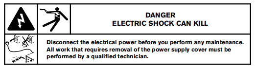
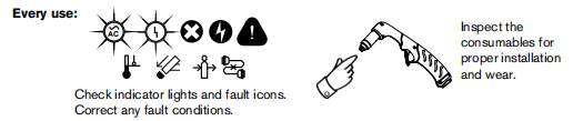
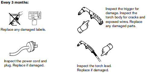

Inspect the consumables
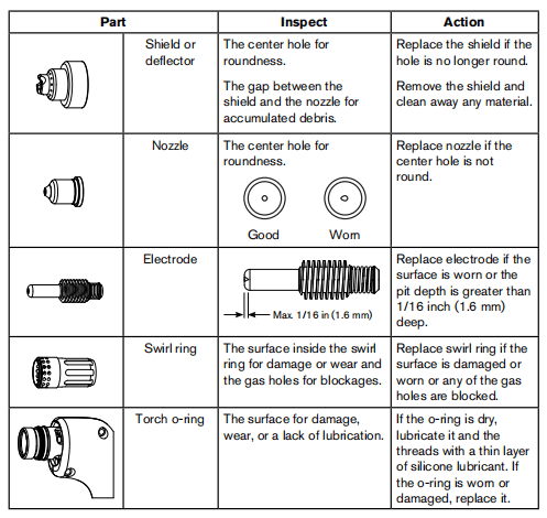
Basic troubleshooting
The following table provides an overview ofthe most common problems that can arise when using the Powermax65 or Powema85 and explains how to solve them.Note: Fault icons and corresponding fault codes appearin the LCD display.Refer to 5-6 Fault codes and solutionsIf you are unablo to fix the problem by following this basic troubleshooting guide, or if you need further assistance:
1. Call your Hyperthem distributor or authorized Hypertherm repair facility.
2. Call the nearest Hypertherm office listed in the front of this manual
| Problem | Solutions |
| The ON/OFF power switch is set to ON (I),but the power ON LED is not illuminated. | Verify that the power cord is plugged into the receptacle. Verify that the power is ON at the main power panel or at the line-disconnect switch box. Verify that the line voltage is not too low (more than 15% below the rated voltage) Verify that the circuit break has not been tripped. |
| The arc does not transfer to the workpiece. | Clean the area where the work clamp contacts the workpiece to ensure a good metal-to-metal connection. Inspect the workclamp for damage and repair as necessary. The pierce-height distance may be too lange. Move the torch closer to the workpiece and fire the torch again. |
Fault codes and solutions
A label with descriptions for these common fault codes can be found inside the front cover of this manual. Peel off the label and place it on the rear of the power supply for reference.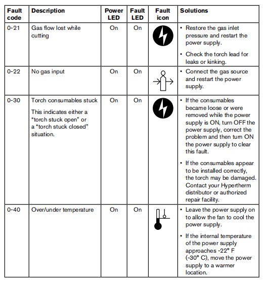
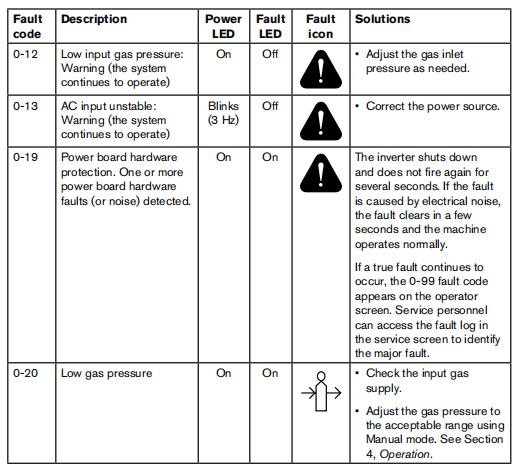
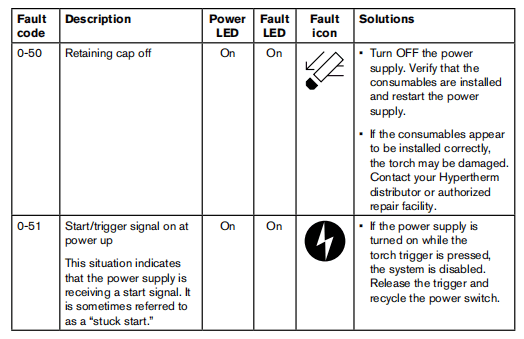
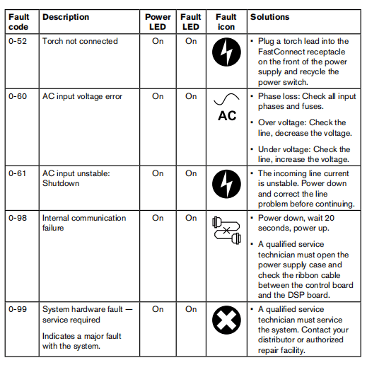
Replace the gas filter element
1. Tun OFF the power, disconnect the power cord,and make sure the gas supplyis disconnected
2. Position the rear of the power supply sothe removable gas fiter bowl is easily accessible.
3. Grasp the fiter bowl with your right hand.
4. Push down the thumb latch and rotate the fiter bow approximately 45 degrees to the right.
5.Pull the lifter bow stright down toremove. You can seo the white filter clement and retaining nut
6. Unscrew (counterclockwise)the plastic retaining nut that secures the fiter element.
7. Replace the dirty element with a new element. Reinstall (clockwise) the plastic retaining nutto finger-tightenly.8. Insert thefiter bowl with the thumb latch positioned approximately 45 degrees to the right of center. This is the same onientation in which the fiter bow was pulled down and removed.9. Vertically align the filter bowl (with metalguard) and firmly push the fiter bowlup to the top of the receptacle to seat the bowl.lt is helpfulto lift the bow with your left index finger under the nut on the bottom of the bow.10. Once the bowl is seated properly, rotate the bowl 45 degnees to the left untilyou hear the thumb latch clickinto place.
11. Reconnect the gas supply hose to the power supply and check for leaks.
12. Reconnect the electrical power and tum ONthe power switch.
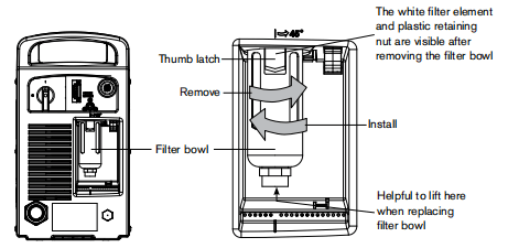
Section 6 Parts
Power supply parts
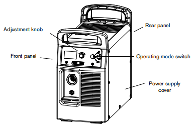
Part number
228643
Description
Kit: Powermax 65/85 front panel
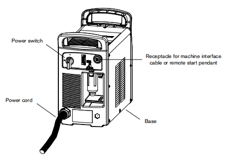
Part number
228691
023206
023279
228350
228351
127204
228539
228697
123896
Description
Kit: Powermax 65/85 CSA power cord
Machine interface cable (startplasma, arc transfer ground),25 ft(7.6m), spade connectorsMachine interface cable (startplasma, arc transfer ground), 50f(15.2m). spade connectorsMachine interface cable (start plasma, arc transfer, adjustable voltage dvider, ground),25t (7.6 m),spade connectorsMachine interface cable (start plasma, arc transfer, adjustable voltage divider, ground),50f(15m), spade connectorsPowermax45/65/85 Machine interface receptacle coverKit RS485 board with cables (65/85)Kit PMX65/85 Machine Interface Cable (nternal cable whv-div board)Machine interface cable (start, stop, transfer signals),50ft(152m),D-subconnector with screws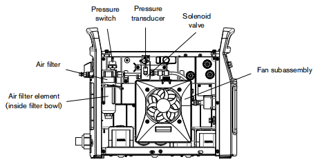
Part number
228696
228685
228695
228688
228687
228689
Description
Kit: Powermax 65/85 fan subassembly
Kit: Powermax 65/85 air filter
Kit: Powermax 65/85 air filter element
Kit: Powermax 65/85 pressure switch
Kit: Powermax 65/85 solenoid valve
Kit: Powermax 65/85 pressure transducer
H65/H85 hand torch replacement parts
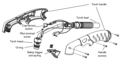
The entire hand torch and lead assembly can be replaced, or individual component parts can be replaced. Part numbers starting with 083 and 087 indicate complete torch and lead assemblies.
Part number
083247
083248
083249
087085
087086
087087
228717
228721
228714
058519
Description
H65 Hand torch assembly with 25t(7.6m) lead
H65 Hand torch assembly with 50 t (152 m) lead
H66 Hand torch assembly with 75 t (22.9m) lead
H85 Hand torch assembly with 25t(7.6m) lead
H85 Hand torch assembly with 50 t (152 m) lead
H85 Hand torch assemby with 75t(229m) lead
Kit: H65/H85 Torch handle replacement
Handle screws,#4×1/2 slottod TORX pan head, S/B
Kit H65/H85/H65s/H85s Safety tnigger with sping replacement
KitH65/H85 Torch main body replacement
o-ring
H65/85s Hand Torch replacement parts
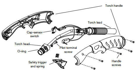
The entire hand torch and lead assembly can be replaced or indiwdual component parts can be replaced. Part numbers starting with 083 and 087 indicate complete torch and lead assemblies.
Part number
083251
083252
083253
087089
087090
087091
228718
075714
228721
228715
058519
Description
H65s Hand torch assembly with 25 t (7.6 m) lead
H65s Hand torch assembly with 50 ft (15.2 m) lead
H65s Hand torch assembly with 75 ft (22.9 m) lead
H85s Hand tonch assembly with 25 t (7.6 m) lead
H85s Hand torch assembly with 50 ft (15.2 m) lead
H85s Hand torch assembly with 75 t (22.9 m) lead
Kit: H65s/H85s Torch handle replacement
Handle screws, #4 x 1/2 slotted TORX pan head, S/B
Handle screws, #4 x 1/2 slotted TORX pan head, S/B
KitH65s/H85s Torch main body replacement
O-ring
Hand torch consumables
Part number
Drag cutting
220818
220854
220941
220819
220816
220842
220857
Description
Shield
Retaining cap
45A Nozzle
65A Nozzle
85A Nozzle
Electrode
Swirl ring
Gouging
220798
220854
220797
220842
220857
65/85A shield
Retaining cap
65/85A nozzle
Electrode
Swirl ring
Finecut 45 A
220931
220854
220930
220842
220947
Deflector
Retaining cap
Nozzle
Electrode
Swirl ring
M65/M85 machine torch replacement parts
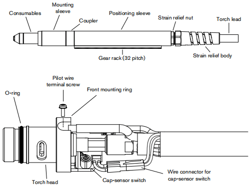
The entire machine torch and lead assembly can be replaced, or individual component parts can be replaced Partnumbers starting with 083 and 087indicate complete torch and lead assemblies.
Part number
083254
083255
083256
083257
083258
087092
087093
087094
087095
087096
228737
228738
228735
228736
228716
228720
058519
Description
M65 Machine torch assembly with 15t(4.6 m) lead
M65 Machine torch assembly with 25ft (7.6 m) lead
M65 Machine torch assembly with 35t(10.7m) lead
M65 Machino torch assembly with 50ft (15.2 m) lead
M65 Machine torch assembly with 75ft (22.9 m) lead M85 Machine torch assembly with 15ft (46 m) lead M85 Machine torch assembly with 25ft (7.6 m) lead M85 Machine torch assembly with 35t(10.7m) lead M85 Machine torch assembly with 50t (15.2 m) lead M85 Machine torch assembly with 75ft (22.9 m) lead Kit: M65/M85 positioning sleeve Kit: M65/M85 removable gear rack Kit: M65/M65m/M85/M85m front mounting sleeve Kit: M65/M65m/M85/M85m adapter ring (coupler) Kit:M65/M65m/M85/M85mtorch main body replacement Kit: Cap-sensor switch replacement O-ring
M65m/M85m machine torch replacement parts
Note: This illustration shows M65/M85m machine torch. The M65m and M85m mini-machine torches do not have a positioning sleeve and gear rack.
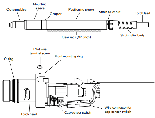
Machine torch consumables
Part number
Description
Shielded
220817
220854
220953
220941
220819
220816
220842
220857
Shield
Retaining cap
Ohmic retaining cap
45A Nozzle
64A Nozzle
85A Nozzle
Electrode
Swirl ring
Accessory
Part number
223206
223207
223208
223209
223210
223211
229370
Description
Kit 85 A Work fead with magnet clamp, 25 ft(7.5 m)
Kit 85 A Work lead with magnet clamp, 50ft(15.2 m)
Kit 85A Work lead with magnetclamp,75ft(22.9m)
Kit 85A Work lead with magnet clamp,75ft(22.9m)
Kit 85 A Work lead with ring terminal, 50ft (15.2 m)
Kit85A Work lead with ring terminal, 75t(229m)
Kit Powermax65/85 Wheel kit assembly
Powermax65/85 labels
Part number
228649
228650
228651
228652
Description
Kit: Powermax65 labels, CSA
Kit: Powermax65 labels, CE
Kit: Powermax85 labels, CSA
Kit: PowermaxB5 labels CE