
Hypertherm Powermax 105a Plasma Arc Cutting System Operator Manual

Powermax105
Operator Manual
807580
Revision 0
English
Contents
Section 1
Specifications
Safety information
System description
Where to find information
Power supply dimensions
Component weights(105 A systems)
Powermax 105 power power supply ratings
Duramax 75º hand torch dimensions
Duramax 15º hand torch dimensions
Duramax 180º full-length machine torch dimensions
Duramax 180º mini machine torch dimensions
Powermax 105 cutting specifications
Symbols and markings
Noise levels
IEC symbols
Section 2
Power supply setup
Unpack the powermax system
Claims
Contents
Position the power supply
Prepare the electrical power
Install a line-disconnect switch
Requirements for grounding
Power connection for the Powermax 105
Three-phase power cord and plug installation
Extension cord recommendations
Extension cord specifications
Engine-driven generator recommendations
Prepare the gas supply
Additional gas filtration
Connect the gas supply
Section 3
Basic system Operations
Controls and indicators
Rear controls
Front controls and LEDs
Status screen
Operating the Powermax 105
Connect the electrical power, gas supply, and torch lead
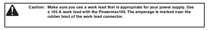
Attach the work lead to the power supply
Attach the work clamp to the workpiece
Turn ON the system
Set the operating mode switch
Check the indicators
Manually adjusting the gas pressure
Adjusting the currrent (amperage)
Electrode end-of-life detection feature
Understanding duty-cycle limitations
Section 4
Hand torch setup
Instruction
Consumable life
Hand torch components
Choose the hand torch consumables
Drag-cutting 105A consumables
Drag-cutting 45A, 65A, 85A consumables
Hand torch consumables
Gouging consumables
Finecut consumables
Install the hand torch consumables
Connecting the torch lead
Section 5
Hand cutting
Using the hand torch
Operate the safety trigger
Hand torch cutting hints
Start a cut from the edge of the workpiece
Pierce a workpiece
Gouge a workpiece
Gouge profile
Varying the gouge profile
Common hand-cutting faults
Section 6
Machine torch setup
Introduction
Consumable life
Machine torch components
Converting a full-length machine torch to a mini machine torch
Mount the torch
Choose the machine torch consumables
Machine torch consumables
Mechanized shielded 105A consumables
Mechanized shielded 45A,65a,85A consumables
Mechanized shielded with ohmic 105A consumables
Mechanized shielded with ohmic 45A,65A,85A consumables
Mechanized unshielded 105A consumables
Mechanized unshielded 45A,65A,85A consumables
Gouging consumables
Finecut shielded consumables
Finecut unshielded consumables
Install the machine torch consumables
Aligning the torch
Connecting the torch lead
Using the cut charts
Estimated kerf-width compensation
105A shielded consumables
105A shielded cutting (Mild steel)
105A shielded cutting (Stainless steel)
105A shielded cutting(Aluminum)
85A shielded consumables
85A shielded cutting (Mild steel)
85A shielded cutting (Stainless steel)
85A shielded cutting(Aluminum)
65A shielded consumables
65A shielded cutting (Mild steel)
65A shielded cutting (Stainless steel)
65A shielded cutting(Aluminum)
45A shielded consumables
45A shielded cutting (Mild steel)
45A shielded cutting (Stainless steel)
45A shielded cutting(Aluminum)
FineCut consumables
FineCut (Mild Steel)
FineCut (Stainless Steel)
Low Speed FineCut (Mild Steel)
Low Speed FineCut (Stainless Steel)
105 A Unshielded consumables
105 A Unshielded cutting (Mild Steel)
105 A Unshielded cutting (Stainless Steel)
105 A Unshielded cutting (Aluminum)
85 A Unshielded consumables
85 A Unshielded cutting (Mild Steel)
85 A Unshielded cutting (Stainless Steel)
85 A Unshielded cutting (Aluminum)
65 A Unshielded consumables
65 A Unshielded cutting (Mild Steel)
65 A Unshielded cutting (Stainless Steel)
65 A Unshielded cutting (Aluminum)
45 A Unshielded consumables
45 A Unshielded cutting (Mild Steel)
45 A Unshielded cutting (Stainless Steel)
45 A Unshielded cutting (Aluminum)
Section 7
Mechanized Cutting
Connecting an optional remote-start pendant
Connecting an optional machine interface cable
Machine interface pinout
Setting the five position voltage divider.
Accessing raw arc voltage
Connecting an optional RS485 serial interface cable
Using the machine torch
Setting up the torch and table
Understand and optimize cut quality
Cut or bevel angle
Dross
Piercing a workpiece using the machine torch
Common machine-cutting faults
Section 8
Troubleshooting and System Tests
Controls and indicators
Theory of operation
General
200-600 V CSA 3-phase power supply functional description
230-400 V CE,380 V CCC/230-400 V CE 3-phase power supply functional description
400 V CE,380 V CCC 3-phase power supply functional description
Sequence of operation
Troubleshooting preparation
Test equipment
Troubleshooting procedures and sequence
External inspection
Internal inspection
Initial resistance check
Check the power switch
Hypertherm IGBT tester
Indicator LEDs and device tests
IGBT test preparation
IGBT device test using the Hypertherm tester
Troubleshoot the Hypertherm IGBT tester
Schematic for building an IGBT tester
IGBT device test using a non-Hypertherm tester
200-600 V CSA power supply overview
230-400 V CE,380 V CCC/230-400 V CE power supply overview
380 V CCC,400 V CE power supply overview
200-600 V CSA power supply overview(power board removed)
230-400 V CE,380 V CCC/230-400 V CE power supply overview(power board removed)
380 V CCC,400 V CE power supply overview(power board removed).
Fault codes
Displaying the service screen
Important fault icons
Performing a cold restart
Fault codes and solutions
Troubleshooting guide
System tests
Test 1-Voltage input
Test 2-DC Power Buss
Test 3-Output diodes
Test 4-Inverter and PFC temperature sensor
Test 5-Flyback circuit (DC minor voltages)
Test 6-Torch stuck open (TSO)/torch stuck closed(TSC)
Test 7-Start signal
Test 8-Torch cap switch
Test 9-Electronic regulator
Test 10-Pressure sensor
Test 11-Fan
Test 12-AUX switch
Section 9
Power Supply Component Replacement
Replacing the air filter element
Replacing the work lead connector
Installing the optional filter kit
Replacing the power supply cover
Replacing the Mylar® barrier
Installing the machine interface cable with voltage divider board
Installing the machine interface cable
Installing the RS485 serial interface cable
Replacing the power cord
Replacing the strain relief connector
Replacing the power switch
Replacing the control board
Replacing the DSP board
Replacing the power board
Replacing the input diode bridge
Replacing the output diode bridge
Replacing the pilot arc IGBT
Replacing the inverter IGBT module
Replacing the PFC IGBT module
Replacing the snubber resistor
Replacing the damper resistor
Replacing the thermal sensor
Replacing the fan shroud
Replacing the fan
Replacing the pressure transducer
Replacing the pressure switch
Replacing the air filter subassembly
Replacing the solenoid valve
Replacing the gas tubing
Replacing the bulk capacitors
Replacing the torch quick disconnect receptacle
Replacing the work lead receptacle.
Replacing the output inductor
Replacing the transformer
Replacing the PFC inductor
Replacing the front end panel
Replacing the rear end panel
Installing the machine interface cable for raw arc voltage
Section 10
Torch Component Replacement
Hand torch:Replacing the start switch
Hand torch:Replacing the cap-sensor switch
Hand torch:Replacing the handles
Hand torch:Replacing the trigger
Hand torch:Replacing the torch body
Hand torch:Replacing the torch lead
Hand torch:Replacing the quick disconnect housing
Machine torch:Replacing the mounting sleeve
Machine torch:Replacing the cap-sensor switch
Machine torch:Replacing the torch body
Machine torch:Replacing the coupler
Machine torch:Replacing the gear rack
Machine torch:Replacing the positioning sleeve
Machine torch:Replacing the torch lead
Machine torch:Replacing the quick disconnect housing
Section 11
Parts
Power supply parts
Exterior front
Exterior rear
Interior,power board side (200-600 V CSA)
Interior, power board side (230-400 V CE)
Interior,power board side (400 V CE/380 V CCC)
Interior,fan side
Heat sink assembly
200-600 V CSA heat sink components
230-400 V CE heat sink components
400 V CE/ 380 V CCC heat sink components
Duramax 75°hand torch replacement parts
Duramax 15° hand torch replacement parts
Hand torch consumables
Duramax 180° full-length machine torch replacement parts
Duramax 180° mini machine torch replacement parts
Machine torch consumables
Accessory parts
Powermax105 labels
Safety-critical parts
200-600 VCSA
230-400 V CE
400 V CE/380 VCCC
Power supply fan side
Recommended spare parts
Section 12
Wiring Diagrams
Powermax Generic Timing Chart
Schematic diagram(CSA,230-400 V CE,380 V CCC/230-400 VCE)
Schematic diagram (380 V CCC, 400 V CE)
Section 1 Specifications
Safety information
Before you set up and operate your Hypertherm system,read the separate Safety and Compliance Manua/ included with your system for important safety information.
System description
The Powermax105 is a highly portable,105-amp,handheld and mechanized plasma cutting system appropriate for a wide range of applications.The Powermax system uses air or nitrogen to cut electrically conductive metals, such as mild steel,stainless steel,or aluminum.Smart Sense technology automatically adjusts the gas pressure according to cutting mode and torch lead length for optimum cutting.
The Powermax105 can cut thicknesses up to 38 mm(1-1/2 inches) and pierce thicknesses up to 22 mm(7/8 inch). FastConnect provides a simple push-button torch connection to the power supply for quick torch changes.
The typical handheld Powermax system includes a DuramaxT series 75° hand torch with a consumables box and work lead cable.Reference materials include:operator manual, quick setup card,registration card,setup DVD,and safety manual.
The typical mechanized Powermax system includes a Duramax series 180° full-length machine torch with a consumables box,work lead cable,and remote-start pendant.Reference materials include:operator manual,quick setup card, registration card,setup DVD,and safety manual.
See your Hypertherm distributor for other system configurations.You can order additional styles of torches, consumables,and accessories such as the plasma cutting guide.See the Parts section for a list of spare and optional parts.
Powermax105 power supplies are shipped without a plug on the power cord.See the Power Supply Setup section for more information.
Note:Some CCC certified configurations do not ship with a power cord. Powermax105 3-phase systemsinclude the following models:
•The 200-600 V CSA model is a universal power supply that can automatically adjust to operate with AC voltages from 200 to 600 V.
•The 230-400 V CE model can automatically adjust from 230 to 400 V.
•The 380 V CCC/230-400 V CE model can automatically adjust from 230 to 400 V. Note:To maintain CE certification,install power cord kit 228886.
•The 400 V CE model is 400 V only. The 380 V CCC model is 380 V only.
Where to find information
System specifications such as size, weight,detailed electrical specifications, and cut speeds can be found in this section. For information on:
•Setup requirements, including power requirements, grounding, power cord configuration, extension cord requirements, and generator recommendations- See the Power Supply Setup section.
•Handheld and machine torch consumables, cut charts, and torch setup information- See the Hand Torch Setup or Machine Torch Setup section.
•Information about the controls and LEDs, steps for system operation, and hints for improving cut quality- See the basic system operations,Hand cutting, and Mechanized cutting sections.
The manual also contains sections on troubleshooting and ordering parts for your system.
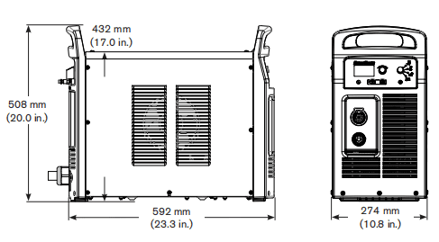
Power supply demensions
Component weights (105 A systems)
| 200-600V CSA | 230- -400 VCE | 400 V CE | 380V CCc | 380V CCC/230-400V CE | |
| Power supply | 40 kg (88 lbs) | 39 kg (87 lbs) | 35 kg (78 lbs) | With power cord 35 kg (78 lbs) No power cord 34kg (74 lbs) | No power cord 36 kg (79 lbs) |
| With7.6 m (25 ft) hand torch and 7.6 m (25ft) | 45 kg (100 lbs) | 45 kg (100 lbs) | 41 kg(91lbs) | With power cord 41 kg(91lbs) No power cord 39 kg (87 lbs) | No power cord 42 kg (92 lbs) |
| Hand torch 7.6 m (25 ft) | 3.3kg (7.3 bs) |
| Hand torch 15 m (50 f) | 5.9 kg(13.0 lbs) |
| Hand torch 23 m (75 ft) | 8.4kg(18.5 lbs) |
| Machine torch 4.6 m(15ft) | 2.4 kg (5.4 bs) |
| Machine torch 7.6 m (25 ft) | 3.4 kg (7.6 lbs) |
| Machine torch 11 m (35 ft) | 4.5kg(10.0 lbs) |
| Machine torch 15 m (50 ft) | 6.2 kg (13.7 lbs) |
| Machine torch 23 m (75 ft) | 8.7 kg(19.3 lbs) |
| Work lead 7.6 m (25 ft) | 2.4 kg (5.3 lbs) |
| Work lead 15 m (50 ft) | 4.4 kg (9.6 lbs) |
| Work lead 23 m (75 f) | 6.1 kg(13.4 lbs) |
Powermax105 power supply ratings
| Rated open-circuit voltage(Uo) | 200-600V CSA 230-400VCE 380VCCC/230-400VCE 400VCE 380VCCC | 300VDC 288VDC 288VDC 292VDC 280VDC |
| Output characteristic | Drooping | |
| Rated output current (,) | 30-105A | |
| Rated output voltage (U) | 160VDC | |
| Duty cycle at 40C(104’F) | 200-600VCSA 230-400VCE or 380VCCC/230-400VCE 400VCE 380VCCC | 80%@105A,480-600V.3-PH 70%@105A240V,3-PH 54%@105A208V,3-PH 50%@105A200V,3-PH 100%@94A,380V,3-PH 100%@88A,240V,3-PH 100%@77A,208V,3-PH 100%@74A,200V,3-PH 80%@105A,400V,3-PH |
| Operating temperature | -10Fto40C(14″to104° F) | |
| Storage temperature | -25″to 55″C(-13″to1319F) | |
| Power factor 200-600VCSA,3-PH 230-400VCE,3-PH 380VCCC/230-400VCE,3-PH 400VCE,3-PH 380VCCC,3-PH | 0.94-0.77 0.94-0.92 0.94-0.92 0.94 0.94 | |
| Rsoe- Short Circuit Ratio (CE models only) | U,- Volts ACrms, 3-PH R.ce 230-400VCE 275 400VCE 230 | |
| EMC dassification CISPR11(CE models only)4 | Class A | ||
| Input voltage (U)/ Input current (l) at rated output (U MAx, l wx) (See the Power Supply Setup section for more information.) | 200-600V CSA 380VCCC/230-400V CE23 230-400VCE23 380 V CCC | 200/208/240/480/600V,3-PH.50/60Hz 58/56/49/25/22 A 230-400V.3-PH50/60Hz 50/29A 400V,3-PH,50/60Hz 28A 380V.3-PH,50V60Hz 30A | |
| Gas type | Air | Nitrogen | |
| Gas quality | Clean, dry,ol-free per ISO8573-1 Class1.2.2 | 99.959% pure | |
| Recommended gas inlet flow rate/ pressure | Cutting:220slpm(460scfh,7.7scfm)@5.9bar(85ps) Gouging:230 slpm (480scfh,8Oscfm)@ 4.8 bar (7Ops) | ||
1 Defined as aplot of output voltage versus output current.
2 Equipment complies with IEC 61000-3-12provided that the short-circuit power Sg is greater than or equal to 5528 KVA at the interface point between the user’s supply and the public system.t is the responsibility of the installer or user of the equipment to ensure, by consutation with the distrbution network operator ifnecessary, that the equipment is connected only to a supply with a short-circuit power S. greater than or equal to 5528KVA
3 This product meets the technical requirements ofIEC 61000-3-3andis not subject to condtional connection 4 WARNING:This Cass A equipment is notintended for use in residential locations where the electrical power is provided by the public low-voltage supply system. There may be potential difficulties in ensuring electromagnefic compatibility in those locations, due to conducted as well as radiated disturbances. 5 Equipment complies with IEC 61000-3-12provided that the short-circuit power Sgis greater thanorequal to4462 KVA at the interface point between the user’s supply and the public system.lt is the responsibility of the installeror user of the equipment to ensure, by consultation with the distrbution network operator ifnecessary, that the equipment is connected only to asupply with ashort-circuit power Se greater than or equalto 4462KVA
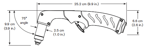
Duramax 75° hand torch dimensions
Duramax 15° hand torch dimensions

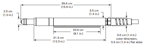
Duramax 180° full-length machine torch dimensions
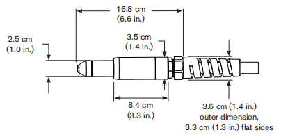
Duramax 180° mini machine torch dimensions
Powermax 105 cutting specifications
| Handheld cut capacity (material thickness) | |
| Recommended cut capacity at 500mm/min (20ipm) | 32mm(1-1/4in) |
| Recommended cut capacity at 250mm/min (10ipm) | 38mm(1-1/2 in.) |
| Severance capacity at125mm/min (5ipm)” | 50mm (2in) |
| Pierce capacity (material thickness) | |
| Pierce capacity for handheld cutting or mechanized cutting with programmable torch height control | 22mm (7/8in) |
| Pierce capacity for mechanized cutting without programmable torch height control | 20mm (3/4 in) |
| Maximum cut speed- (mild steel) | |
| 6mm(1/4in) | 5600 mm/min(220 ipm) |
| 12mm(1/2in) | 2400 mm/min (95 ipm) |
| 20mm(3/4in) | 1300 mm/min (50 ipm) |
| 25 mm(1in) | 760mm/min (30 ipm) |
| 32 mm(1-1/4 in.) | 510 mm/min (20 ipm) |
| Gouging capacity | |
| Metal removal rate on mild steel (65A) | 4.8 kg/hr (10.7lbs/hr) |
| Metal removal rate on mild steel (85A) | 8.8 kg/hr(19.5lbs/hr) |
| Metal remowal rate on mild steel (105A) | 9.8 kg/hr (21.7lbs/hr) |
| Duramax series torch weights (refer topage 1-5 Component weights (105A systems)]) | |
| Duty cycle and voltage information (refer to page 1-6Powermax105 power supply ratings) | |
*Cut capacity speeds are not necessarily maximum speeds. They are the speeds that must be achieved to be rated at that thickness.* Maximum cut speeds are the results of Hypertherm’s laboratory testing. Actual cutting speeds may vary based on different cutting applications.
Symbols and markings
Your Hypertherm product may have one or more of the following markings on or near the data plate. Due to differences and conflicts in national regulations, not all marks are applied to every version of a product.![]()
S mark symbolThe S mark symbolindicates that the power supply and torch are suitable for operations carried out in environments with increased hazard of electrical shock perIEC60974-1.![]()
CSA markHypertherm products with aCSA mark meet the United States and Canadian regulations for product safety. The products were evaluated, tested, and certifed by CSA-nterational Altemafvely the productmay haveamadk by one of the ather Nationally Recognized Testing Laboratories (NRTL) accredited in both the United States and Canada, such as Underwriters Laboratories, Incorporated (UL) or TOv.![]()
CE markingThe CEmarking signifies the manufacturer’s dedaration of confomity toapplicable European directives and standards.Only those versions of Hypertherm products with a CE marking located on or near the data plate have been tested for compliance with the European Low Voltage Directive and the European Electromagnetic Compatibity (EMC) Directive.EMC flters needed to comply with the European EMC Directive are incorporated within versions of the product with a CE marking.
GOST-RmarkCEversions of Hypertherm products thatincude a GOST-R mark of conformity meet the product safety and EMC requirements for export to the Russian Federation.![]()
C-Tick markCE versions of Hypertherm products with a c-Tickmark comply with the EMC regulations required for salein Australia and New Zeafand.![]()
CCCmarkThe China Compulsory Certification (CCC)markindicates that the product has beentested and found compliant withproduct safely regulations required for sale in China
UkrSEPRO markCE versions of Hypertherm products thatinclude aUkrSEPRO mark of conformity meet the product safety and EMC requirements for export to the Ukraine.
Noise levels
Acceptable noise levels as defined by national and local codes may be exceeded by this plasma system. Always wear proper ear protection when cutting or gouging. Any noise measurements taken are dependant on the specific environment in which the system is used. See also Noise can damage hearing in the Safety and Compliance Manual included with your system.
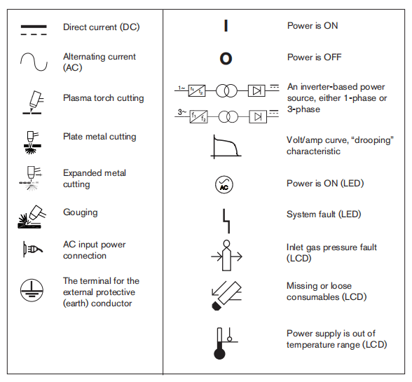
IEC symbols
The following symbols may appear on the power supply data plate, control labels, switches, LEDs, and LCD screen.
Section 2 Power Supply Setup
Unpack the Powermax system
1. Verify that all items on your order have been received in good condition. Contact yourdistributorifany parts are damaged or missing.2. Inspect the power supply for damage that may have occurred during shipping. f there is evidence of damage, refer to Claims below. All communications regarding this equipment must include the model number and the serial number located on the back of the power supply.3. Before you set up and operate this Hyperthem system,read the separate Safely and Compliance Manual included with your system for important safety information.
Claims
•Claims for damage during shipment -lf your unit was damaged during shipment,you must file a claim with the carrier. Hypertherm will fumish you with a copy of the bll of lading upon request.lIf you need additional assistance, call the nearest Hypertherm office listed in the front of this manual. •Claims for defective or missing merchandise -lf any component is missing ordefective, contact your Hypertherm distributor. If you need additional assistance, call the nearest Hypertherm offce isted in the front of this manual.
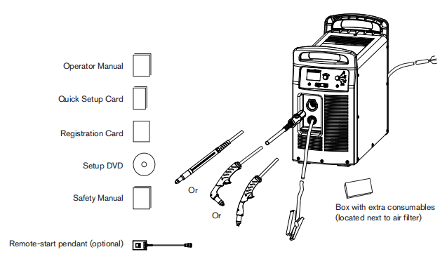
Contents
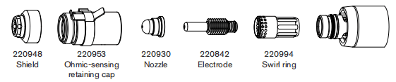
The following illustration shows typical system components. A vinyl cap is installed on torches that ship with new systems. Consumables are included in the consumables box.
Position the power supply
Locate the power supply near an appropriate power receptacle for your installation:
•200-600 volts (3-phase,CSA certified) •230-400 volts (3-phase,CE certified) •380/230-400 volts (3-phase,CCc/cE certifed) without power cordNote: To maintain CE certification, install power cord kit 228886. •400 volts (3-phase,CE certifed) •380 volts (3-phase,CCCcertified).The power supply has a3 m (10ft) power cord (depending upon the model). Alow at least O.25 m (10 inches) of space around the power supply for proper ventilation. The power supply is not suitable for use in rain or snow. To avoid toppling. do not set the power supply on an incline greater than 10 degrees.
Prepare the electrical power
Hypertherm (designated HYP on the data plate) input current ratings are used to detemine conductor sizes for power connection and installation instructions. The HYP ratingis determined under maximum normal operating conditions and the higher HYP input current value should be used for installation purposes. The madmum output voltage wil vary based on your input voltage and the circuit’s amperage. Because the current draw varies during startup, slow-blow fuses are recommended as shown in the charts on page 2-6. Slow-blow fuses can withstand currents up to 1O times the rated value forshort periods of time.
Install a line-disconnect switch
Use a line-disconnect switch for each power supply so that the operator can tum off the incoming power quickly in an emergency. Locate the switch so that itis easily accessible to the operator. Installation must be performed by a licensed electrician according to national and local codes. The interrupt level of the switch must equal or exceed the continuous rating of the fuses. In addition, the switch should:•Isolate the electrical equipment and disconnect all live conductors from the incoming supply volage when in the OFF postion. •Have one OFF and one ON position that are clearly marked with O(OFF) andI(ON). •Have an external operating handle that can be locked in the OFF position. •Contain a power-operated mechanism that serves as an emergency stop. •Have appropriate slow-blow fuses installed. See page 2-6 Power connection for the Powermax105 for recommended fuse sizes.
Requirements for grounding
To ensure personal safety, proper operation, and toreduce electromagnetic interference (EMD, the powersupply must be properly grounded. •The power supply must be grounded through the power cord according to national and local electrical codes •Three-phase service must be of the 4-wire type with agreen or green/yellow wire for protective earth ground and must comply with national and local reguirements. •Refer to the separate Safety and Compliance Manua included with your system for more information on grounding.
Power connection for the Powermax105
Powermax1053-phase systems include the following models: •The 200-600V CSA model is a universal power supply that can automatically adjust to operate with AC voltages fom 200 to 600 V. •The230-400VCE model can automatically adjust from 230to400V. •The 380V CCC/230-400V CE model can automatically adjust fom 230to 400 V.Note:To maintain CE certification, install power cord kt 228886. •The 400v CE model is 400 Vonly. •The380v CCC modelis 380V only. The rated output is 30-105A,160VDC
| 200-600VCSA, | |||||
| Input voltage (V) | 200 | 208 | 240 | 480 | 600 |
| Ihput cument (A)at rated output(16.8kw | 58 | 56 | 49 | 25 | 22 |
| Input current (A)at arc stretch | 82 | 82 | 78 | 40 | 35 |
| Fuse,slow-blow (A) | 80 | 80 | 80 | 40 | 40 |
| 230-400VCE | ||
| Input voltage (V) | 230 | 400 |
| Input current (A)at rated output(16,8kw) | 50 | 29 |
| Input current (A)at arc stretch | 80 | 46 |
| Fuse, slow-blow (A) | 80 | 50 |
| 380V CCC/230-400V CE | |||
| Input voltage (V) | 230 | 400 | 380 |
| Ihput cument (A)at rated output(16.8kw | 50 | 29 | 30 |
| Input current (A)at arc stretch | 80 | 46 | 42 |
| Fuse,slow-blow (A) | 80 | 50 | 50 |
| 400V | |
| Input voltage (V) | 400 |
| Ihput cument (A)at rated output(16.8kw | 28 |
| Input current (A)at arc stretch | 44 |
| Fuse,slow-blow (A) | 50 |
| 380V CCC | |
| Input voltage (V) | 380 |
| Ihput cument (A)at rated output(16.8kw | 30 |
| Input current (A)at arc stretch | 42 |
| Fuse,slow-blow (A) | 50 |
Three-phase power cord and plug installation
Powermax105 power supplies are shipped with the following power cords: •CSA models: 6 AWG 4-wire power cord •230-400VCE:10mm2,4-wire HAR power cord •380VCCC/230-400V CE ships without a power cordNote:To maintain CE certification, install power cord kit 228886. •400V CE:6mm2,4-wire HAR power cord •380VCCC:6mm2,4-wire CCCpower cord (some models ship without apower cord)To operate the Powermax105,usea plug that meets national and local electrical codes. The plug must be connected to the power cord by a licensed electrician.Strip and prepare the power cord wires as shown below.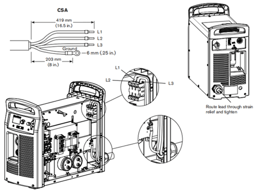
Extension cord recommendations
Any extension cord must have an appropriate wire size for the cord length and system voltage. Use a cord that meets national and local codes.
The table on the next page provides the recommended gauge sizes for various lengths and input voltages. The lengths in the tables are the length of the extension cord only; they do not include the power supply’s power cord.
Extension cord specifications
| Extension cord length | <3m (10ft) | 3-7.5m (10-25ft) | 7.5-15m (25-50ft) | 15-30m (50-100ft) | 30-45m(100-150ft) | |
| 200-600V CSA | ||||||
| Input voltage (VAC) | Phase | mm²(AWG) | mm²(AWG) | mm²(AWG) | mm²(AWG) | mm²(AWG) |
| 200-240 | 3 | 16(6) | 16(6) | 16(6) | 25(4) | 35(2) |
| 480-600 | 3 | 6(10) | 6(10) | 6(10) | 6(10) | 6(10) |
| 230-400V CE | ||||||
| Input voltage (VAC) | Phase | mm² | mm² | mm² | mm² | mm² |
| 230 | 3 | 16 | 16 | 16 | 25 | 25 |
| 400 | 3 | 10 | 10 | 10 | 10 | 10 |
| 380V CCC/230-400V CE | ||||||
| Input voltage (VAC) | Phase | mm² | mm² | mm² | mm² | mm² |
| 230 | 3 | 16 | 16 | 16 | 25 | 25 |
| 400 | 3 | 10 | 10 | 10 | 10 | 10 |
| 380 | 3 | 10 | 10 | 10 | 10 | 10 |
| 400V CE | ||||||
| Input voltage (VAC) | Phase | mm² | mm² | mm² | mm² | mm² |
| 400 | 3 | 10 | 10 | 10 | 10 | 10 |
| 380V CCC | ||||||
| Input voltage (VAC) | Phase | mm² | mm² | mm² | mm² | mm² |
| 380 | 3 | 10 | 10 | 10 | 10 | 10 |
Engine-driven generator recommendations
Generators used with the Powermax105 should satisfy the following requirements: 200-600VCSA 3-phase, 50/60 Hz,200-600VAC(480 VAC recommended for best performance) 230-400VCE 3-phase, 50/60 Hz,230-400VAC(400 VAC recommended for best performance) 380VCCC/230-400VCE 3-phase, 50/60 Hz,230-400VAC(400VAC recommended for best performance) 400VCE 3-phase, 50/60 Hz, 400 VAC (400VAC recommended for best performance) 380VCCC 3-phase, 50/60 Hz, 380 VAC (380 VAC recommended for best performance)
| Engine drive rating | System output current | Performance (arc stretch) |
| 30 kw | 105A | Full |
| 22.5-25 | 105A | Limited |
| 20 kw | 85A | Full |
| 15kw | 70A | Limited |
| 15 kw | 65A | Full |
| 12kw | 65A | Limited |
| 12kw | 40A | Full |
| 8 kw | 40A | Limited |
| 8 kw | 30A | Full |
Note: Based on the generator rating, age., and condition, adjust the cutting current as needed. If a fault occurs while using a generator, tuming the power switch quickly to OFF and then to ON again (sometimes called a “quick reset’) may not clear the fault. Instead, tur OFF the power supply and wait 6o to 7O seconds before turning ON again
Prepare the gas supply
The air can be supplied by a compressor or from high-pressure cylinders A high-pressure regulator must be used on either type of supply and must be capable of delivering gas to the air inlet on the power supply.If the supply quality is poor, cut speeds decrease, cut quality deteriorates, cutting thickness capability decreases, and the life of the consumables shortens. For optimal perfomance, the gas should be compliant with ISO8573-1:2010, Class 1.2.2 (that is,it should have a maximum number of solid particulate per m3 of <20,000for particle sizes in the range of 0.1-0.5 microns, <400 for particle sizes in the range of o.5-1microns,and <1Ofor particle sizes in the range of 1-5 microns). The maximum water vapor dew point should be <-40°C(-40F.The maximum oil (aerosol, iquid, and vapor) content should be less than O.1mg/m3.
Additional gas filtration
When site conditons introduce moisture, oil, or other contaminants into the gas line,use a3-stage coalescing fltration system, such as the Eliminizer filter kit (part number 228890) available from Hypertherm distributors. A 3-stage filtering system works as shown below to clean contaminants from the gas supply.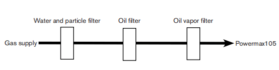
The filter system should be installed between the gas supply and the power supply. Additional gas filtration may increase the required minumum inlet pressure.
Connect the gas supply
Connect the gas supply to the power supply using an inert-gas hose with a 9.5mm (3/8 inch)internal diameter and a 1/4 NPT quick-disconnect coupler, or a 1/4 NPT x G 1/4 BSPP (CE units) quick-disconnect coupler.
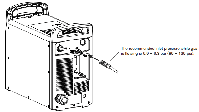
Minimum inlet pressure (while gas is flowing)
This table shows the minimum required inlet pressure when the recommended inlet pressure is not available.
| Torch lead length | |||
| 7.6m (25ft) | 15.2m(50ft) | 22.9 m (75ft) | |
| Cuting | 5.2 bar (75 ps) | 5.5 bar (80 psi) | 5.9 bar (85 psi) |
| Gouging | 4.1 bar(60psi) | 4.5 bar (65 psi) | 4.8 bar (70 psi) |
Gas fiow rates
| Cuting | 220 slpm (460 scfh, 7.7 scfm) at a minimum 5.9 bar (85 ps) |
| Gouging | 230 slpm (480scfh,B.Oscfm)ata minimum 4.8 bar(70ps) |
Section 3 Basic System Operations
Controls and indicators
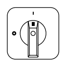
Powermax105 power supplies have the following: ON/OFF switch, adjustment knob, automatic/manual pressure setting mode selector, current/gas selector, operating mode switch, indicator LEDs, and a status screen. These controls and indicators are described on the following pages.
Rear controls
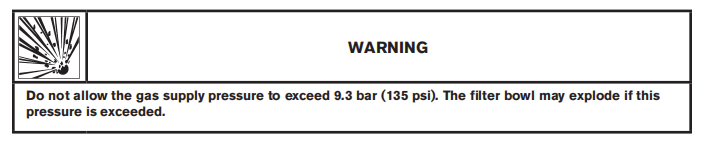
ON (D)/OFF (O) power switchActivates the power supply and its control circuits.
Front controls and LEDs

Fault LED (yellow)When iluminated, this LED indicates that there is afault with the power supply.![]()
Power ON LED (green)When iluminated, this LED indicates that the power switch has been set tol(ON) and that the safetyinterlocks are satisfied. When blinking. the power supply has afaut.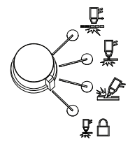
Operating mode switchThe operating mode switch can be setin one of four postions:•Continuous pilot arc. Cuts expanded metal or grate.•Non-continuous pilot arc. Cuts or pierces metal plate. This is the standard setting for normal drag-cuting.•Gouge. Gouges metal plate.•Torch lock. Same as the non-continuous pilot arc mode except the torch is locked in the ON position when yourelease the trigger during a cut. The torch goes out when the transfer is lost or the torch is retriggered.
Automatic/manual pressure setting mode selectorThe selector switches between automatic and manual mode. In automatic mode, the power supplyautomatically sets the gas pressure based upon the torch type and lead length and the adjustmentknob sets only the amperage. In manual mode, the adjustment knob sets either the gas pressure or theamperage. This LED is iluminated in manual mode.Note: Manual mode should be used by experienced users who need to optimize the gas setting (overide the automatic gas setting) for aspecific cutting application.When you switch from manual mode to automatic mode, the power supply automatically sets the gas pressure and the amperage setting is unchanged. When you switch from automatic mode to manual mode, the power supply remembers the previous manualgas pressure setting and the amperage setting is unchanged. When you reset the power, the power supply remembers the previous mode, gas pressure, and amperage settings.![]()
Current/gas selector
When in manual mode, this selector toggles between amperage and gas pressure for manualadjustments using the adjustment knob.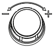
Adjustment knobThis knob adjusts the amperage. When operating in manual mode, this knob can also adjust thegas pressure, overriding the automatic setting for optimized applications.
Status screen
The status screen shows system status and faut information.
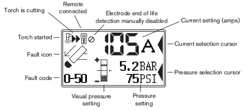
Gas pressure indicators
In manual mode, the gas pressure is displayed in bar and psi. The gas pressure bar is also a visualindicator of the gas pressure.![]()
Gas pressure barWhen the arrow is centered in the vertical bar (the reference pressure of the automatic pressure seting), the gas pressure is set to the preset (factory-defined) value. If the pressure is higher than the preset value, the arrow appears above the mid-point of the bar. f the pressure is lower than the preset value, the arrow appears below the mid-point of the bar.Note:In automatic mode, the power supply adjusts the pressure to the preset value. You can use manual mode to adjust the pressure to satisfy the needs of aparticular cutting job.Refer to page3-10 Manually adjusting the gas pressure.
System status icons
The screen displays icons to indicate the system’s status.
![]()
Torch startedIndicates that the torch has received a start signal.![]()
Torch is cuttingIndicates that the cutting arc has transferred to the metal and the torch is cutting.![]()
Remote controlIndicates that a remote control or CNC is controling the power supply using serial communications. All local controls are disabled.![]()
Electrode end-of-ife detection manually disabledIndicates that the electrode end-of-ife detection feature is manually disabled.
Fault codes
When a power supply or torch faut occurs, the system displays a fault codein the lower-left comer of the status screen and displays a corresponding fault icon above the code. The first digitis always zero. The other two digits identify the problem. Fault code information is induded later in this manual.Note: Only one fault code is displayed. If more than one fault occurs at the same time,only the fault code with the highest priority is displayed.
Fault icons
The faut icons that appear on the let side of the status screen are described below.A fault code also appears to identify the fault. Refer to the troubleshooting information later in this manual.
WarningThe system continues to run.
FaultThe system stops cutting. If you can not correct the problem and restart the system,contact your distributor or Hypertherm Technical Service.
ErrorThe system requires service. Contact your distributor or Hypertherm Technical Service.
Torch cap sensorIndicates that the consumables are loose, improperly installed, or missing. Tum OFF the power, properly install the consumables, and turn ON the system again to reset the power supply.
TemperatureIndicates that the temperature of the power supply power module is outside the acceptable operating range.
GasIndicates that the gas is disconnected from the rear of the power supply or there is a problem with the gas supply.
Internal Serial Communications InterfaceIndicates a problem with the SCl communications between the control board and the DSP board.
Operating the Powermax105
Follow the steps below to begin cutting or gouging with the Powermax system.Note: This section provides basic operating instructions. Before operating your Powermaxina production environment, refer to the Hand Torch Setup section or the Machine Torch Setup section.
Connect the electrical power, gas supply, and torch lead
For information on connecting the proper plug to the power cord, refer to the Power Supply Setup section. Plug in the power cord and connect the gas supply line. For more information about the electrical requirements and the gas supply requirements of the Powermax, see the Power Supply Setup section. To connect the torch, push the FastConnect connector into the receptacle on the front of the power supply You will attach the work lead in the next section.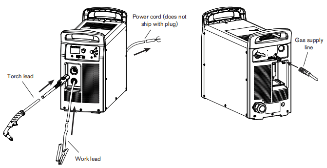
Attach the work lead to the power supply
1.Insert the work lead connectorinto the receptacle on the front of the power supply.Note: The receptacle is keyed. Align the key on the work lead connector with the opening at the top of the receptacle on the power supply.
2.Push the work lead connector all the way into the receptacle on the power supply and turn clockwise, approximately 1/4 turn, until the connectoris fully seated against the stop in order to achieve an optimal electrical connection.
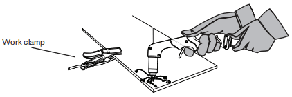
Attach the work clamp to the workpiece
The work clamp must be connected to the workpiece while you are cutting. If you are using the Powermax105 with a cutting table, you can connect the work lead directly to the table instead of attaching the work clamp to the workpiece.See your table manufacturer’s instructions.Note the following: •Ensure that the work clamp and the workpiece make good metal-to-metal contact. Remove rust, dirt, paint, coatings, and other debris to ensure the work lead makes proper contact with the workpiece. •For the best cut quality, attach the work clamp as close as possible to the area being cut
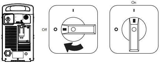
Turn ON the system
Set the ON/OFF switch to the ON(I) position.
Set the operating mode switch
Use the operating mode switch to select the type of work you want to perform. In automatic gas mode, Smart Sense” technology automatically adjusts the gas pressure according to the selected cutting mode and torch lead length for optimum cutting.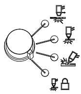
For cutting expanded metal, grates, metal containing holes, or any job that requires a continuous pilot arc. Using this mode to cut standard metal plate reduces consumable life. For cutting or piercing metal. This is the standard setting for nomal drag-cutting. For gouging metal (Note: Using this mode while cutting results in poor cut quality) Locks the torch in the ON (fire) position. With this option selected, press the trigger to fire the torch. You can then release the trigger while continuing to cut. Press the tigger again to stop the arc. The torch goes out when transferis lost
Check the indicators
Verify the following:• The green power ON LED on the front of the power supply isilluminated.• The Fault LED is not illuminated.• No error icons appear in the status screen.If a fault icon appears in the status screen, or the Fault LEDisiluminated, orthe power ON LED is blinking, correct the fault condition before continuing. More troubleshooting information is included later in this manual.
Manually adjusting the gas pressure
For normal operations, the power supply automatically adjusts the gas pressure. fyou need to adjust the gas pressure for a specific application, you can use manual modeto do so.Note: Manual mode should be used by experienced users who need to optimize the gas setting (override the automatic gas setting) fora specific cutting application.When you switch from manual mode to automatic mode, the power supply automatically sets the gas pressure and the amperage setting is unchanged. When you switch from automatic mode to manual mode, the power supply remembers the previous manual gas pressure setting and the amperage setting is unchanged.
When you reset the power, the power supply remembers the previous mode, gas pressure, and amperage settings.
To adjust the pressure: 1. Press the automatic/manual pressure setting mode selector so that the LED next to the selectorilluminates. Refer to the diagram on page 3-2 Front controls and LEDs. 2 Press the current/gas selector until the selection cursor is opposite the gas pressure setting in the status screen. 3. Tum the adjustment knob to adjust the gas pressure to the desired level Watch the arrowin the pressure bar as you adjust the pressure.
Adjusting the current (amperage)
Tum the adjustment knob to adjust the current for your particular cutting application.
If the system is in manual mode, do the following to adjust the amperage. 1. Press the current/gas selector until the selection cursor is opposite the amperage setting in the status screen. 2.Tum the adjustment knob to change the amperage. 3. If you wish to exit manual mode, press the automatic/manual pressure setting mode selector. The LED goes off.
Note:When you exit manual mode, the gas pressure resets to the factory-optimized value.
When you switch between manual mode and automatic mode, the power supply retains the amperage setting. When you reset the power, the power supply returns to the previous mode (automatic mode or manual mode) and remembers the previous amperage setting.
Electrode end-of-life detection feature
The electrode end-of-life detection feature on the Powermax105 protects the torch and workpiece from damage by automatically stopping power to the torch when the electrode reaches its end of life. Fault code 0-32 also displays on the front panel status screen.If you have the current set below 55 A,this feature is automatically disabled without displaying the icon on the status screen.To manually disable the feature, press the current/gas selector button (see figure below) five times on the control pane. The system must be in the auto mode and the selector presses must be less than one second apart. Re-enable the feature by repeating this procedure. An icon (see figure below) displays on the status screen when the feature is manually disabled.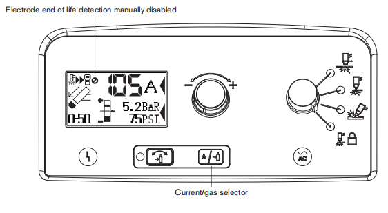
Understanding duty-cycle limitations
The duty cycle is the amount of time, in minutes, that a plasma arc can remain on within a 10-minute period when operating at an ambient temperature of 40°C(104°F).With a Powermax105: •At 105 A(480-600VCSA,400VCE,380VCCC,the arc can remain on for 8 minutes out of 10 minutes without causing the unit to overheat (80% duty cycle). •At 94A(480-600VCSA,400VCE, 380V CCC), the arc can remain on for 1O minutes out of 10(100%)See the Specifications section for a complete list of duty cycle specifications. If the duty cycle is exceeded, the power supply overheats, the temperature fault icon appears in the status screen, the arc shuts off, and the cooling fan continues to run. You can not resume cutting until the temperature fault icon disappears and the fault LED goes off.
Section 4 Hand Torch Setup
Introduction
Duramax series hand torches are available for Powermax105 systems. The FastConnect quick-disconnect system makes it easy to remove the torch for transport or to switch from one torch to the other if your applications require the use of different torches. The torches are cooled by ambient air and do not require special cooling procedures. This section explains how to set up your hand torch and choose the appropriate consumables for the job.
Consumable life
How often you need to change the consumables on your torch will depend on a number of factors:
•The thickness of the metal being cut.•The average length of the cut.•The air quality (presence of oil, moisture, or other contaminants).•Whether you are piercing the metal orstarting cuts from the edge.•Proper torch-to-work distance when gouging or cutting with unshielded consumables.•Proper pieroe height.•Whether you are cuting in “continuous pilot arc” mode or normal mode. Cutting with a continuous pilot arc causes more consumable wear.Under normal conditions, the nozzle wil wear out first when hand cutting. As generalrule, a set of consumables lasts approximately 1 to 3 hours of actual “arc on” time for hand cutting.You will find more infomation about proper cutting techniques in the Hand Cutting section.
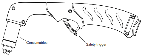
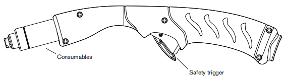
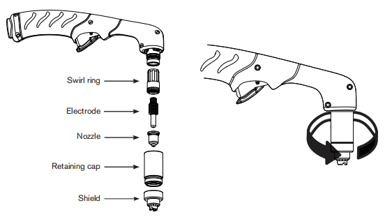
Hand Torch components
Note: Torches ship without consumables installed.
Duramax 75° hand torch
Duramax 15° hand torch
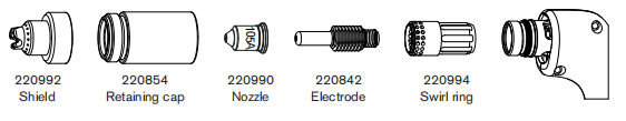
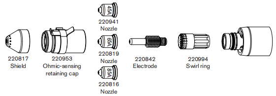
Choose the hand torch consumables
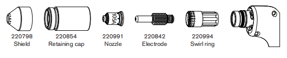
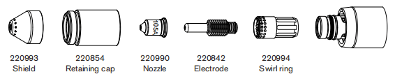
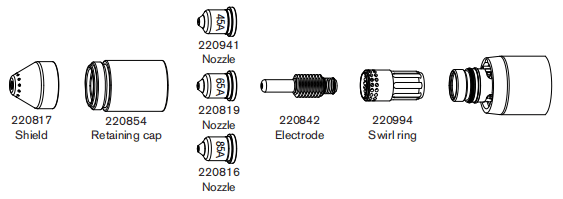
Hypertherm includes a box of consumables with your system.Bothstyles of hand torches shown on the previous page use the same consumables. Hand torches use shielded consumables. Therefore, you can drag the torch tip along the metal. Consumables for hand cutting are shown on the next page. Notice that the retaining cap and electrode are the same for cutting, gouging, and FineCut applications. Only the shield, nozze, and swirl ring are dfferent. For the best cut quality on thin matenials (approximately 4mm/10GA or less),you may prefer to use FineCut consumables, or use a45 Anozzle and reduce the amperage to that setting.
Drag-cutting 105 A consumables
Drag-cutting 45A, 65A, 85A consumables
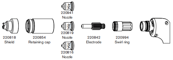
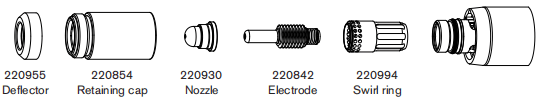
Hand torch consumables
Gouging consumables
Finecut consumables
Install the hand torch consumables
To operate the hand torch, a complete set of consumable parts must be installed. Pull off the vinyl cap before installing your consumables.
With the power switch in the OFF(O) position, install the torch consumables as shown below.
Connecting the torch lead
The Powermax105 is equipped with FastConnectm, aquick-disconnect system for connecting and disconnecting handheld and machine torch leads. When connecting or disconnecting atorch first turn OFF the system. To connect the torch, push the connector into the receptacle on the front of the power supply.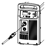
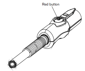
To remove the torch, press the red button on the connector and pull the connector out of the receptacle.
Section 5 Hand Cutting
Using the hand torch
Operate the safety trigger
The hand torches are equipped with a safety trigger to prevent accidental firings. When you are ready to use the torch, fip the trigger’s safety cover forward (toward the torch head) and press the red torch trigger as show below.
Hand torch cutting hints
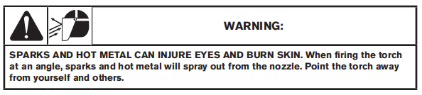
•Drag the torch tip lightly along the workpiece to maintain a steady cut. •While cutting, make sure that sparks exit from the bottom of the workpiece. The sparks should lag slightly behind the torch as you cut (15-30°angle from vertical). •If sparks spray up from the workpiece, move the torch more slowly, or set the output current higher.
•With either the Duramax 75″ hand torch or Duramax 15° hand torch, hold the torch nozzle perpendicular to the workpiece so that the nozzle is at a 90 angle to the cutting surface. Observe the cutting arc as the torch cuts.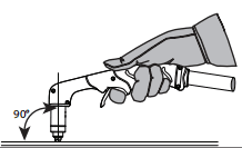
•If you fire the torch unnecessarily, you will shorten the life of the nozzle and electrode.
•Puling, or dragging. the torch along the cutis easier than pushing it. •For straight-line cuts, use a straight edge as a guide. To cut circles, use a template ora radius cutter attachment (a circle cutting guide). See the Parts section for part numbers for the Hypertherm plasma cutting guides for cutting circles and making bevel cuts.
Start a cut from the edge of the workpiece
1. With the work clamp attached to the workpiece, hold thetorch nozzle perpendicular (90) to the edge of the workpiece.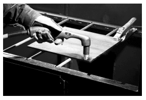
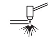
2. Press the torch’s trigger to start the arc. Pause at the edgeuntil the arc has cut completely through the workpiece.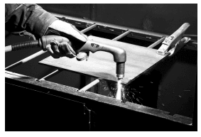
3. Drag the torch tip lightly across the workpiece to proceedwith the cut. Maintain a steady, even pace.
Gouging a workpiece

- Hold the torch so that the torch tip is within 1.5mm(1/16inch) from the workpiece before firing the torch.

2. Hold the torch at a 45″angle to the workpiece with a small gap between the torch tip and the workpiece. Press the trigger to obtain a pilot arc. Transfer the arc to the work piece.
3. Maintain an approximate 45″ angle to the workpiece as you feed into the gouge. Push the plasma arc in the direction of the gouge you want to create. Keep a small distance between the torch tip and the molten metal to avoid reducing consumable life or damaging the torch.Changing the torch’s angle changes the dimensions of the gouge.
Gouge profile
You can vary the gouge profile by varying the speed of the torch over the workpiece, varying the torch-to-work standoff distance, varying the angle of the torch to the workpiece, and varying the current output of the power supply.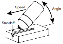
| Operating parameters | |
| Speed | 50.8-63.5cm/min(20-25ipm) |
| Standoff | 6.4-9.5mm(1/4-3/8in) |
| Angle | 35-40* |
Typical Gouge Profile for 65A
Metal removal rate on mild steel 4.8 kg/hr(10.7lbs/hr)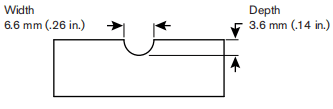
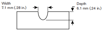
Typical Gouge Profile for 85A
Metal removal rate on mild steel
8.8 kg/hr(19.5lbs/hr)
Typical Gouge Profile for 105A
Metal removal rate on mild steel9.8 kg/hr (21.7 lbs/hr)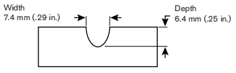
Varying the gouge profile
The following actions have the stated effects on the gouge profie: • Increasing the speed of the torch will decrease width and decrease depth.• Decreasing the speed of the torch will increase width and increase depth.• Increasing the standoff of the torch will increase width and decrease depth.• Decreasing the standoff of the torch will decrease width and increase depth.• Increasing the angle of the torch (more vertical) will decrease width and increase depth.• Decreasing the angle of the torch (less vertical) wil increase width and decrease depth.• Increasing the current of the power supply will increase width and increase depth.• Decreasing the current of the power supply will decrease width and decrease depth.
Common hand-cutting faults
The torch does not cut completely through the workpiece. The causes can be: • The cut speed is too fast.• The consumables are worn.• The metal being cutis too thick for the selected amperage.• Gouging consumables are installed instead of drag-cutting consumables.• The work clamp is not attached properly to the workpiece.• The gas pressure or gas flow rate is too low.Cut quality is poor. The causes can be: • The metal being cut is too thick for the amperage.• The wrong consumables are being used (gouging consumables are installed instead of drag-cutting consumables, for example).• You are moving the torch too quickly or too slowly.The arc sputters and consumables ife is shorter than expected. The cause can be: • Moisture in the gas supply.• Incorrect gas pressure.• Consumables incorrectly installed.
Section 6 Machine Torch Setup
Introduction
Duramax series machine torches are available for Powermax105 systems. The FastConnect quick-disconnect system makes it easy to remove the torch for transport or to switch from one torch tothe other if your applications require the use of different torches. The torches are cooled by ambient air and do not require special cooling procedures. This section explains how to set up your machine torch and choose the appropriate consumables for the job.
Consumable life
How often you need to change the consumables on your torch will depend on a number of factors:
• The thickness of the metal being cut.• The average length of the cut.• The air quality (presence of oil, moisture, or other contaminants).• Whether you are piercing the metal or starting cuts from the edge.• Proper torch-to-work distance when gouging or cutting with unshielded consumables.• Proper pierce height.• Whether you are cutting in “continuous pilot arc” mode or normal mode. Cutting with a continuous pilot arc causes more consumable wear.
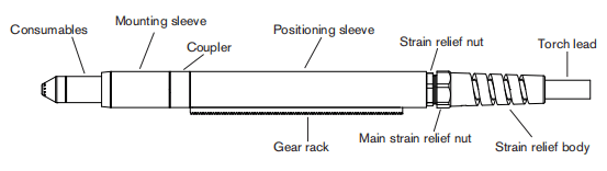
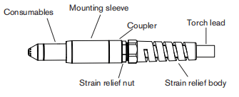
Machine torch components
Duramax 180° full-length machine torch
Duramax 180° mini machine torch
Before using either style of machine torch, you must: • Mount the torch on your cutting table or other equipment.• Choose and install the consumables.• Align the torch square to the plate.• Attach the torch lead to the power supply.• Set up the power supply for remote starting with either the remote-start pendant or a machine interface cable.
Converting a full-length machine torch to a mini machine torch
You can convert a full-length machine torch to amini machine torch by removing the positioning sleeve. Note:If you are converting a full-length machine torch to amini machine torch and mounting the torch at the same time, skip this section and follow the instructions on page 6-7 Mountthe torch. Refer to the figures on page 6-4 Machine torch components and follow these instructions. Note:While disconnecting and reconnecting the torch parts, maintain the same orientation between the torch head and torch lead. Twisting the torch head in relation to the torch lead can cause damage.1. Disconnect the torch lead from the power supply and remove the consumables from the torch.2.Unscrew the strain relief body from the strain relief nut and slide the strain relief body back along the torch lead.3.Unscrew the strain relief nut from the positioning sleeve and slide the nutback along the torch lead.4. Unscrew the positioning sleeve from the coupler.5. Unscrew the coupler from the mounting sleeve.6. Remove the three screws from the consumables end of the mounting sleeve and slide the mounting sleeve off the front of the torch body.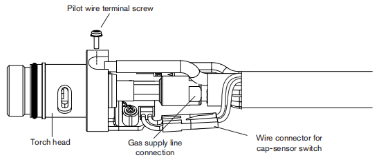
7. Disconnect the wire connector for the cap-sensor switch.8. Use a #2 Philips screwdriver to remove the screw that secures the torch’s pilot wire to the torch body.9.Use 1/4-inch and 3/8-inch wrenches,oradjustable wrenches,to loosen the nut that secures the gas supply line to the torch lead. Set the torch body aside.10. Slide the coupler and positioning sleeve off the front of the torch lead.11. Slide the coupler over the torch lead.12. Reconnect the gas line to the torch lead.13. Reattach the torch’s pilot wire to the torch body using the screw.14. Reconnect the cap-sensor switch’s wire connector.15. Slide the mounting sleeve over the front of the torch body. Align the slot on the frontof the mounting sleeve (next to one of the three screw holes) with the cap-sensor plunger on the torch body.16. Attach the mounting sleeve to the torch body using the three screws.17. Screw the coupler into the mounting sleeve.18. Screw the strain relief nut into the coupler.19. Screw the strain relief body into the strain relief nut.
Mount the torch
Depending on the type of cutting table you have, you may or may not need to disassemble the torch to route it through the track and mount it. If your cutting table’s track is large enough for you to thread the torch through it without removing the torch body from the lead, do so and then attach the torch to the lifter per the manufacturer’s instructions. Note:The Duramax machine torches can be mounted on a wide variety of X-Y tables, trackburers, pipe bevelers, and other equipment. Install the torch per the manufacturer’s instructions and follow the instructions below for disassembly if necessary. If you need to disassemble and reassemble the torch, refer to the figures on page 6-4 Machine torch components and follow these instructions. Note:While disconnecting and reconnecting the torch parts, maintain the same orientation between the torch head and torch lead. Twisting the torch head in relation to the torch lead can cause damage.1. Disconnect the torch lead from the power supply and remove the consumables from the torch.2. Unscrew the strain relief body fom the strain relef nut and slide the strain relief body back along the torch lead.3. Unscrew the strain relief nut from the positioning sleeve (full-length machine torch) and slide the nut back along the torch lead.4. Unscrew the positioning sleeve from the coupler.5. Unscrew the coupler from the mounting sleeve.6. Remove the three screws from the consumables end of the mounting sleeve and side the mounting sleeve off the front of the torch body.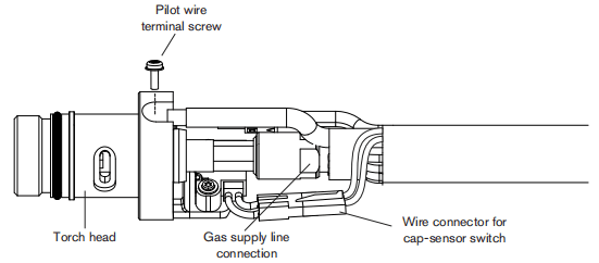
7.Disconnect the wire connector for the cap-sensor switch.8.Use a#2Phillips screwdriver to remowe the screw that secures the torch’s pilot wire to the torch body.9. Use 1/4-inch and 3/8-inch wrenches, or adjustable wrenches, to loosen the nut that secures the gas supply line to the torch lead. Set the torch body aside.10. Slide the coupler, positioning sleeve full-length machine torch), strain relief nut,and strain relef body off the front of the torch lead.11. If you do not need the gear rack on a full-length machine torch, slide the gear rack from the positioning sleeve toward the consumables end of the sleeve.12. Route the torch lead through the cutting table’s track13. Slide the strain relief body and strain relief nut over the torch lead.14. If you are mounting aful-length machine torch, slide the positioning sleeve over the torch head if you are mounting a mini machine torch, set aside the positioning sleeve.15. Slide the coupler over the torch lead.16. Reconnect the gas line to the torch lead.17. Reattach the torch’s pilot wire tothe torch body using the screw.18. Reconnect the cap-sensor switch’s wire connector.19. Slide the mounting sleeve over the front of the torch body. Align the slotonthe front of the mounting sleeve (next to one of the three screw holes) with the cap-sensor plunger on the torch body.20. Attach the mounting sleeve to the torch body using the three screws21. Screw the coupler into the mounting sleeve.22. If you are mounting a full-length machine torch, screw the positioning sleeve into the couple. If you are mounting a mini machine torch, the strain relief nut attaches directly to the coupler in the next step.23. Reconnect the strain relief nut and strain relief body.24. Attach the torch to the lifter per the manufacturer’s instructions.
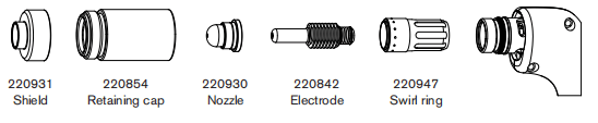
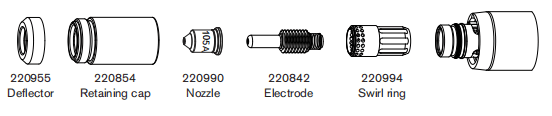
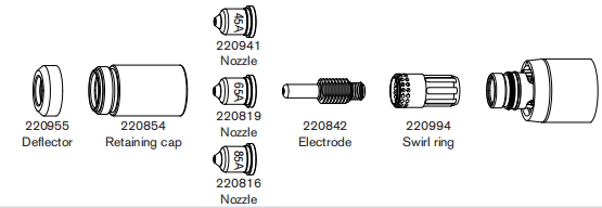
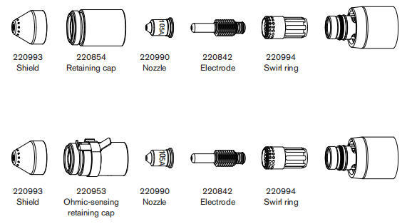
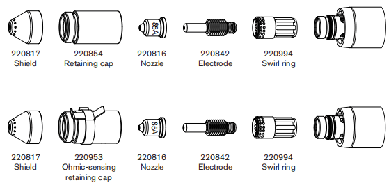
Choose the machine torch consumables
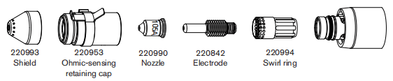
Powermax systems with the Duramax 180° full-length machine torch or Duramax 180 mini machine torch are shipped with a box of consumables. In addition, an ohmic-sensing retaining cap is avalable for use with shielded consumables. With shielded consumables, the torch tip may touch the metal when cutting. With unshielded consumables,you must keep the torch a small distance,about 2-3mm(.08-.12inch),away from the metal. Unshielded consumables generally have a shorter life than shielded consumables. Depending upon which system you order, you may receive a starter consumable kit with a standard retaining cap or ohmic retaining cap. Both styles of machine torches use the same consumables.
Machine torch consumables
Mechanized shielded 105 A consumables
Mechanized shielded 45A65A,85 A consumables
Mechanized shielded with ohmic 105 A consumables
Mechanized shielded with ohmic 45 A, 65A, 85A consumables
Mechanized unshielded 105 A consumables
Mechanized unshielded 45 A, 65A, 85A consumables
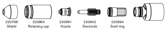
Gouging consumables
Finecut shielded consumables
Finecut unshielded consumables
Install the machine torch consumables
To operate the machine torch, a complete set of consumable parts mustbe installed: shield,retaining cap, nozzle, eledtrode, and swirl ring.With the power switch in the OFF (O) position,install the machine torch consumables in a manner similar to the hand torch consumables. Refer to the Hand torch setup secion.
Aligning the torch
Mount the machine torch perpendicular to the workpiece in order to get a vertical cut. Use a square to align the torch at 0° and 90°.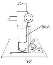
Connecting the torch lead
The Powermax105 is equipped with FastConnectmu,a quick-disconnect system for connecting and disconnecting handheld and machine torch leads. When connecting or disconnecting a torch, first turn OFF the system. To connect the torch, push the connector into the receptacle on the front of the power supply.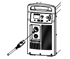
To remove the torch, press the red button on the connector and pull the connector out of the receptacle.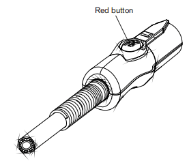
Using the cut charts
The following sections provide cut charts for each set of mechanized consumables. A consumable diagram with part numbers precedes each set of charts. For each consumable type, there are Metric and English charts for mild steel, stainless steel, and aluminum. Each chart contains the following information:• Amperage setting – Except for FineCut charts,the amperage setting at the top left side of the page applies to all the settings given on that page. In FineCut charts, the amperage setting for each thickness, either 45 or40 (45,40,or 3O for low speed),is included in the chart.• Material Thickness – Thickness of the workpiece (metalplate being cut).• Torch-to-Work Distance – For shielded consumables, the distance between the shield and the workpiece during cutting. For unshielded consumables, the distance between the nozzle and the workpiece during cutting.• Initial Pierce Height – Distance between the shield (shielded) or the nozzle (unshielded) and the workpiece when the torch is triggered., prior to descending to the cut height.• Pierce Delay Time – Length of time the triggered torch remains stationary at the pierce height before the torch starts the cutting motion.• Best Quality Settings (cut speed and voltage) – Settings that provide the starting point for finding the best cut quality (best angle, least dross, best cut-surface fnish). Adjust the speed for your application and table to obtain the desired result.• Production Settings (cut speed and voltage)-709%to 809% of the maximum speed ratings. These speeds result in the greatest number of cut parts, but not necessarly the best possible cut quality.Note:The arc voltage increases as the consumables wear and the voltage setting should be increased to maintain the correct Torch-to-Work Distance.Each cut chart lists hot and cold air flow rates. • Hot air flow rate – Plasmais on, the system is operating at running current, and the system is ina steady state at the default system pressure (automatic mode).• Cold air flow rate – Plasma is off and the system is in a steady state with air fowing through the torch at the default system pressure. Note:Hypertherm collected the data under laboratory test conditions using new consumables.
Estimated kerf-width compensation
The widths in the tables below are for reference. The data are obtained with the “Best Quaity” settings. Differences between installations and material composition may cause actual results to vary from those shown in the tables.
Estimated kerf-width compensation – Metric (mm)
| Process | Thickness (mm) | ||||||||||
| 0.5 | 1 | 2 | 3 | 6 | 8 | 10 | 12 | 16 | 20 | 25 | |
| Mild Steel | |||||||||||
| 105A Shielded | 2.1 | 2.2 | 2.2 | 2.2 | 2.5 | 2.7 | 3.3 | ||||
| 85 A Shielded | 1.7 | 1.8 | 1.9 | 2 | 2.2 | 2.4 | 2.6 | ||||
| 65 A Shielded | 1.6 | 1.6 | 1.8 | 1.9 | 2 | 2.2 | 2.3 | ||||
| 45 A Shielded | 1.1 | 1.1 | 1.4 | 1.5 | 1.7 | ||||||
| FineCut | 0.9 | 0.7 | 0.5 | 0.6 | |||||||
| Low Speed FineCut | 0.6 | 0.7 | 0.7 | 0.6 | |||||||
| 105 A Unshielded | 2.1 | 2.3 | 2.5 | 2.4 | 2.7 | 2.9 | 3.2 | ||||
| 85 A Unshielded | 1.7 | 1.8 | 1.9 | 2.0 | 2.1 | 2.1 | 2.3 | ||||
| 65 A Unshielded | 1.6 | 1.6 | 1.7 | 1.8 | 1.9 | 2.0 | |||||
| 45 A Unshielded | 0.5 | 0.9 | 1.3 | 1.3 | |||||||
| Stainless Steel | |||||||||||
| 105A Shielded | 1.9 | 2.1 | 2.3 | 2.3 | 2.3 | 2.6 | 2.9 | ||||
| 85 A Shielded | 1.6 | 1.8 | 1.9 | 2.1 | 2.3 | 2.4 | 2.5 | ||||
| 65 A Shielded | 1.4 | 1.5 | 1.8 | 1.9 | 2.0 | 2.2 | 2.4 | ||||
| 45 A Shielded | 0.9 | 1.1 | 1.5 | 1.6 | 1.8 | ||||||
| FineCut | 0.2 | 0.5 | 0.4 | 0.5 | |||||||
| Low Speed FineCut | 0.6 | 0.5 | 0.6 | 0.5 | |||||||
| 105 A Unshielded | 2.0 | 2.2 | 2.4 | 2.5 | 2.7 | 2.7 | 3.1 | ||||
| 85 A Unshielded | 1.7 | 1.7 | 1.8 | 1.9 | 2.1 | 2.2 | 2.4 | ||||
| 65 A Unshielded | 1.6 | 1.6 | 1.8 | 1.8 | 1.9 | 2.0 | |||||
| 45 A Unshielded | 0.5 | 1.0 | 1.3 | 1.5 | 1.5 | ||||||
| Aluminum | |||||||||||
| 105A Shielded | 2.3 | 2.3 | 2.4 | 2.6 | 2.7 | 3 | 3.5 | ||||
| 85 A Shielded | 2 | 1.9 | 2 | 2.1 | 2.2 | 2.4 | 2.6 | ||||
| 65 A Shielded | 1.9 | 1.9 | 1.9 | 2 | 2.1 | 2.3 | 2.5 | ||||
| 45 A Shielded | 1.5 | 1.5 | 1.6 | 1.5 | |||||||
| 105 A Unshielded | 2.2 | 2.4 | 2.5 | 2.6 | 2.7 | 3 | 3.3 | ||||
| 85 A Unshielded | 1.9 | 1.9 | 1.9 | 2 | 2 | 2.1 | 2.2 | ||||
| 65 A Unshielded | 1.8 | 1.8 | 1.8 | 1.8 | 1.9 | 2 | |||||
| 45 A Unshielded | 1.6 | 1.5 | 1.4 | 1.5 | |||||||
Estimated kerf-width compensation – English (inches)
| Process | Thickness (inches) | ||||||||||
| 22GA | 18GA | 14GA | 10GA | 3/16 | 1/4 | 3/8 | 1/2 | 5/8 | 3/4 | 1 | |
| Mild Steel | |||||||||||
| 105A Shielded | 0.083 | 0.088 | 0.089 | 0.100 | 0.101 | 0.133 | |||||
| 85 A Shielded | 0.068 | 0.071 | 0.073 | 0.078 | 0.090 | 0.095 | 0.100 | ||||
| 65 A Shielded | 0.062 | 0.065 | 0.068 | 0.070 | 0.076 | 0.088 | 0.090 | 0.091 | |||
| 45 A Shielded | 0.035 | 0.054 | 0.055 | 0.061 | 0.065 | 0.066 | |||||
| FineCut | 0.028 | 0.026 | 0.016 | 0.023 | |||||||
| Low Speed FineCut | 0.026 | 0.030 | 0.027 | 0.023 | |||||||
| 105 A Unshielded | 0.083 | 0.097 | 0.098 | 0.107 | 0.111 | 0.125 | |||||
| 85 A Unshielded | 0.070 | 0.073 | 0.075 | 0.080 | 0.085 | 0.090 | |||||
| 65 A Unshielded | 0.062 | 0.064 | 0.066 | 0.068 | 0.075 | 0.081 | |||||
| 45 A Unshielded | 0.020 | 0.050 | 0.051 | 0.054 | 0.057 | 0.059 | |||||
| Stainless Steel | |||||||||||
| 105A Shielded | 0.076 | 0.089 | 0.091 | 0.092 | 0.099 | 0.113 | |||||
| 85 A Shielded | 0.065 | 0.068 | 0.070 | 0.080 | 0.094 | 0.095 | 0.096 | ||||
| 65 A Shielded | 0.056 | 0.062 | 0.068 | 0.073 | 0.076 | 0.090 | 0.093 | ||||
| 45 A Shielded | 0.032 | 0.055 | 0.058 | 0.067 | 0.069 | 0.069 | |||||
| FineCut | 0.025 | 0.019 | 0.014 | 0.027 | |||||||
| Low Speed FineCut | 0.025 | 0.023 | 0.021 | 0.027 | |||||||
| 105 A Unshielded | 0.080 | 0.095 | 0.101 | 0.106 | 0.104 | 0.122 | |||||
| 85 A Unshielded | 0.066 | 0.068 | 0.070 | 0.072 | 0.080 | 0.090 | 0.099 | ||||
| 65 A Unshielded | 0.061 | 0.064 | 0.067 | 0.070 | 0.072 | 0.080 | |||||
| 45 A Unshielded | 0.020 | 0.054 | 0.052 | 0.060 | 0.058 | 0.058 | |||||
| Aluminum | |||||||||||
| 105A Shielded | 0.091 | 0.092 | 0.102 | 0.107 | 0.111 | 0.138 | |||||
| 85 A Shielded | 0.080 | 0.078 | 0.075 | 0.080 | 0.090 | 0.095 | 0.100 | ||||
| 65 A Shielded | 0.073 | 0.074 | 0.075 | 0.076 | 0.083 | 0.091 | 0.100 | ||||
| 45 A Shielded | 0.059 | 0.061 | 0.065 | 0.060 | |||||||
| 105 A Unshielded | 0.089 | 0.098 | 0.102 | 0.106 | 0.117 | 0.132 | |||||
| 85 A Unshielded | 0.075 | 0.075 | 0.075 | 0.080 | 0.082 | 0.088 | |||||
| 65 A Unshielded | 0.070 | 0.070 | 0.070 | 0.070 | 0.072 | 0.079 | |||||
| 45 A Unshielded | 0.062 | 0.058 | 0.057 | 0.061 | |||||||
105A shielded consumables
105 A Shielded cutting (Mild Steel)
| Air fiow rate -slpm/scth | |
| Hot | 217/460 |
| Cold | 250/530 |
Metric
| Material Thickness | Torch-to-Work Distance | Inital Pierce Height | Pierce Delay Time | Best Quality Settings | Production Settings | |||
| Cut Speed | Voltage | Cut Speed | Voltage | |||||
| mm | mm | mm | % | seconds | (mm/min) | Volts | (mm/min) | Volts |
| 6 | 3.2 | 6.4 | 200 | 0.5 | 4140 | 144 | 5090 | 145 |
| 8 | 0.75 | 3140 | 145 | 3870 | 145 | |||
| 10 | 2260 | 145 | 2790 | 145 | ||||
| 12 | 1690 | 145 | 2060 | 148 | ||||
| 16 | 1.0 | 1060 | 149 | 1310 | 149 | |||
| 20 | 780 | 152 | 940 | 152 | ||||
| 25 | Edge Start | 550 | 159 | 580 | 158 | |||
| 30 | 370 | 162 | 410 | 161 | ||||
| 32 | 350 | 166 | 370 | 161 | ||||
| 35 | 290 | 168 | 320 | 165 | ||||
| 40 | 190 | 173 | 210 | 170 | ||||
English
| Material Thickness | Torch-to-Work Distance | Inital Pierce Height | Pierce Delay Time | Best Quality Settings | Production Settings | |||
| Cut Speed | Voltage | Cut Speed | Voltage | |||||
| inches | inches | inches | % | seconds | ipm | Volts | ipm | Volts |
| 1/4 | 0.125 | 0.25 | 200 | 0.5 | 156 | 144 | 192 | 145 |
| 3/8 | 0.75 | 94 | 145 | 116 | 145 | |||
| 1/2 | 62 | 146 | 76 | 148 | ||||
| 5/8 | 1.0 | 42 | 149 | 52 | 149 | |||
| 3/4 | 33 | 151 | 40 | 150 | ||||
| 7/8 | 1.25 | 26 | 154 | 30 | 157 | |||
| 1 | Edge Start | 21 | 160 | 22 | 158 | |||
| 1-1/8 | 15 | 162 | 17 | 160 | ||||
| 1-1/4 | 14 | 166 | 15 | 161 | ||||
| 1-1/2 | 9 | 171 | 10 | 168 | ||||
105 A Shielded cutting (Stainless Steel)
| Air fiow rate -slpm/scth | |
| Hot | 217/460 |
| Cold | 250/530 |
Metric
| Material Thickness | Torch-to-Work Distance | Inital Pierce Height | Pierce Delay Time | Best Quality Settings | Production Settings | |||
| Cut Speed | Voltage | Cut Speed | Voltage | |||||
| mm | mm | mm | % | seconds | (mm/min) | Volts | (mm/min) | Volts |
| 6 | 3.2 | 6.4 | 200 | 0.5 | 4870 | 139 | 6000 | 141 |
| 8 | 3460 | 141 | 4210 | 142 | ||||
| 10 | 2240 | 144 | 2670 | 142 | ||||
| 12 | 0.6 | 1490 | 148 | 1860 | 144 | |||
| 16 | 0.75 | 950 | 149 | 1080 | 149 | |||
| 20 | 8.0 | 250 | 1.25 | 660 | 154 | 810 | 152 | |
| 25 | Edge Start | 440 | 158 | 530 | 156 | |||
| 30 | 340 | 164 | 360 | 160 | ||||
| 32 | 300 | 166 | 320 | 163 | ||||
English
| Material Thickness | Torch-to-Work Distance | Inital Pierce Height | Pierce Delay Time | Best Quality Settings | Production Settings | |||
| Cut Speed | Voltage | Cut Speed | Voltage | |||||
| inches | inches | inches | % | seconds | ipm | Volts | ipm | Volts |
| 1/4 | 0.125 | 0.25 | 200 | 0.5 | 185 | 139 | 224 | 141 |
| 3/8 | 94 | 143 | 112 | 142 | ||||
| 1/2 | 55 | 148 | 68 | 145 | ||||
| 5/8 | 0.75 | 38 | 149 | 43 | 149 | |||
| 3/4 | 0.31 | 250 | 1.25 | 28 | 153 | 34 | 151 | |
| 7/8 | Edge Start | 22 | 156 | 27 | 153 | |||
| 1 | 17 | 158 | 20 | 156 | ||||
| 1-1/8 | 14 | 162 | 16 | 159 | ||||
| 1-1/4 | 12 | 166 | 13 | 163 | ||||
105 A Shielded cutting (Aluminum)
| Air fiow rate -slpm/scth | |
| Hot | 217/460 |
| Cold | 250/530 |
Metric
| Material Thickness | Torch-to-Work Distance | Inital Pierce Height | Pierce Delay Time | Best Quality Settings | Production Settings | |||
| Cut Speed | Voltage | Cut Speed | Voltage | |||||
| mm | mm | mm | % | seconds | (mm/min) | Volts | (mm/min) | Volts |
| 6 | 3.2 | 6.4 | 200 | 0.5 | 5980 | 145 | 7090 | 144 |
| 8 | 0.75 | 4170 | 149 | 5020 | 148 | |||
| 10 | 2640 | 152 | 3280 | 151 | ||||
| 12 | 1.0 | 1910 | 156 | 2450 | 154 | |||
| 16 | 1290 | 157 | 1660 | 155 | ||||
| 20 | 1.25 | 1020 | 163 | 1190 | 162 | |||
| 25 | Edge Start | 660 | 166 | 790 | 165 | |||
| 30 | 430 | 173 | 570 | 171 | ||||
| 32 | 340 | 175 | 490 | 173 | ||||
English
| Material Thickness | Torch-to-Work Distance | Inital Pierce Height | Pierce Delay Time | Cut Speed | Voltage | Cut Speed | Voltage | |
| inches | inches | inches | % | seconds | ipm | Volts | ipm | Volts |
| 1/4 | 0.125 | 0.25 | 200 | 0.5 | 223 | 146 | 265 | 145 |
| 3/8 | 0.75 | 110 | 151 | 136 | 150 | |||
| 1/2 | 1.0 | 71 | 156 | 91 | 154 | |||
| 5/8 | 51 | 157 | 66 | 155 | ||||
| 3/4 | 1.25 | 43 | 162 | 50 | 161 | |||
| 7/8 | Edge Start | 34 | 164 | 40 | 163 | |||
| 1 | 25 | 166 | 30 | 165 | ||||
| 1-1/8 | 20 | 171 | 25 | 169 | ||||
| 1-1/4 | 15 | 175 | 20 | 173 | ||||
85A shielded consumables
85 A Shielded cutting (Mild Steel)
| Air fiow rate -slpm/scth | |
| Hot | 194/412 |
| Cold | 236/500 |
Metric
| Material Thickness | Torch-to-Work Distance | Inital Pierce Height | Pierce Delay Time | Best Quality Settings | Production Settings | |||
| Cut Speed | Voltage | Cut Speed | Voltage | |||||
| mm | mm | mm | % | seconds | (mm/min) | Volts | (mm/min) | Volts |
| 3 | 1.5 | 3.8 | 250 | 0.1 | 6800 | 122 | 9200 | 120 |
| 4 | 0.2 | 5650 | 122 | 7300 | 122 | |||
| 6 | 0.5 | 3600 | 123 | 4400 | 125 | |||
| 8 | 2500 | 125 | 3100 | 127 | ||||
| 10 | 1680 | 127 | 2070 | 128 | ||||
| 12 | 4.5 | 300 | 0.7 | 1280 | 130 | 1600 | 130 | |
| 16 | 1.0 | 870 | 134 | 930 | 133 | |||
| 20 | 6 | 400 | 1.5 | 570 | 137 | 680 | 136 | |
| 25 | Edge Start | 350 | 142 | 450 | 141 | |||
| 30 | 200 | 146 | 300 | 144 | ||||
English
| Material Thickness | Torch-to-Work Distance | Inital Pierce Height | Pierce Delay Time | Cut Speed | Voltage | Cut Speed | Voltage | |
| inches | inches | inches | % | seconds | ipm | Volts | ipm | Volts |
| 10 GA | 0.06 | 0.15 | 250 | 0.0 | 250 | 122 | 336 | 121 |
| 3/16 | 0.2 | 185 | 123 | 220 | 123 | |||
| 1/4 | 0.5 | 130 | 123 | 160 | 126 | |||
| 3/8 | 70 | 126 | 86 | 127 | ||||
| 1/2 | 0.18 | 300 | 45 | 131 | 56 | 131 | ||
| 5/8 | 1.0 | 35 | 134 | 37 | 133 | |||
| 3/4 | 0.24 | 400 | 1.5 | 24 | 136 | 29 | 135 | |
| 7/8 | Edge Start | 19 | 139 | 22 | 138 | |||
| 1 | 13 | 142 | 17 | 141 | ||||
| 1-1/8 | 9 | 145 | 13 | 143 | ||||
| 1-1/4 | 7 | 148 | 10 | 146 | ||||
85 A Shielded cutting (Stainless Steel)
| Air fiow rate -slpm/scth | |
| Hot | 194/412 |
| Cold | 236/500 |
Metric
| Material Thickness | Torch-to-Work Distance | Inital Pierce Height | Pierce Delay Time | Best Quality Settings | Production Settings | |||
| Cut Speed | Voltage | Cut Speed | Voltage | |||||
| mm | mm | mm | % | seconds | (mm/min) | Volts | (mm/min) | Volts |
| 3 | 1.5 | 3.8 | 250 | 0.1 | 7500 | 122 | 9200 | 120 |
| 4 | 0.2 | 6100 | 122 | 7500 | 120 | |||
| 6 | 0.5 | 3700 | 122 | 4600 | 122 | |||
| 8 | 2450 | 124 | 3050 | 124 | ||||
| 10 | 4.5 | 300 | 1550 | 127 | 1900 | 126 | ||
| 12 | 0.7 | 1100 | 131 | 1400 | 130 | |||
| 16 | 1.0 | 700 | 135 | 760 | 134 | |||
| 20 | Edge Start | 480 | 138 | 570 | 137 | |||
| 25 | 300 | 143 | 370 | 141 | ||||
English
| Material Thickness | Torch-to-Work Distance | Inital Pierce Height | Pierce Delay Time | Cut Speed | Voltage | Cut Speed | Voltage | |
| inches | inches | inches | % | seconds | ipm | Volts | ipm | Volts |
| 10 GA | 0.06 | 0.15 | 250 | 0.2 | 275 | 122 | 336 | 120 |
| 3/16 | 200 | 122 | 240 | 121 | ||||
| 1/4 | 0.5 | 130 | 122 | 164 | 122 | |||
| 3/8 | 65 | 126 | 80 | 125 | ||||
| 1/2 | 0.18 | 300 | 36 | 132 | 48 | 131 | ||
| 5/8 | 1.0 | 28 | 135 | 30 | 134 | |||
| 3/4 | Edge Start | 20 | 137 | 24 | 136 | |||
| 7/8 | 16 | 140 | 19 | 139 | ||||
| 1 | 11 | 143 | 14 | 141 | ||||
85 A Shielded cutting (Aluminum)
| Air fiow rate -slpm/scth | |
| Hot | 194/412 |
| Cold | 236/500 |
Metric
| Material Thickness | Torch-to-Work Distance | Inital Pierce Height | Pierce Delay Time | Best Quality Settings | Production Settings | |||
| Cut Speed | Voltage | Cut Speed | Voltage | |||||
| mm | mm | mm | % | seconds | (mm/min) | Volts | (mm/min) | Volts |
| 3 | 1.5 | 3.8 | 250 | 0.1 | 8000 | 122 | 9400 | 121 |
| 4 | 0.2 | 6500 | 123 | 8000 | 123 | |||
| 6 | 0.5 | 3800 | 126 | 4900 | 126 | |||
| 8 | 2650 | 130 | 3470 | 129 | ||||
| 10 | 4.5 | 300 | 1920 | 132 | 2500 | 131 | ||
| 12 | 0.7 | 1450 | 134 | 1930 | 133 | |||
| 16 | 1.0 | 950 | 139 | 1200 | 137 | |||
| 20 | Edge Start | 600 | 143 | 880 | 141 | |||
| 25 | 380 | 146 | 540 | 144 | ||||
English
| Material Thickness | Torch-to-Work Distance | Inital Pierce Height | Pierce Delay Time | Cut Speed | Voltage | Cut Speed | Voltage | |
| inches | inches | inches | % | seconds | ipm | Volts | ipm | Volts |
| 1/8 | 0.06 | 0.15 | 250 | 0.2 | 300 | 122 | 360 | 121 |
| 1/4 | 0.5 | 130 | 127 | 172 | 127 | |||
| 3/8 | 80 | 132 | 104 | 131 | ||||
| 1/2 | 0.18 | 300 | 50 | 135 | 68 | 133 | ||
| 5/8 | 1.0 | 38 | 139 | 48 | 137 | |||
| 3/4 | Edge Start | 25 | 142 | 37 | 140 | |||
| 7/8 | 20 | 144 | 29 | 142 | ||||
| 1 | 14 | 146 | 20 | 144 | ||||
65A shielded consumables
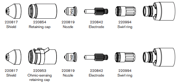
65 A Shielded cutting (Mild Steel)
| Air fiow rate -slpm/scth | |
| Hot | 175/370 |
| Cold | 209/443 |
Metric
| Material Thickness | Torch-to-Work Distance | Inital Pierce Height | Pierce Delay Time | Best Quality Settings | Production Settings | |||
| Cut Speed | Voltage | Cut Speed | Voltage | |||||
| mm | mm | mm | % | seconds | (mm/min) | Volts | (mm/min) | Volts |
| 2 | 1.5 | 3.8 | 250 | 0.1 | 6050 | 124 | 7000 | 121 |
| 3 | 0.2 | 5200 | 125 | 6100 | 123 | |||
| 4 | 0.5 | 4250 | 125 | 5100 | 124 | |||
| 6 | 2550 | 127 | 3240 | 127 | ||||
| 8 | 1700 | 129 | 2230 | 128 | ||||
| 10 | 4.5 | 300 | 0.7 | 1100 | 131 | 1500 | 129 | |
| 12 | 1.2 | 850 | 134 | 1140 | 131 | |||
| 16 | 6.0 | 400 | 2.0 | 560 | 138 | 650 | 136 | |
| 20 | Edge Start | 350 | 142 | 450 | 142 | |||
| 25 | 210 | 145 | 270 | 145 | ||||
English
| Material Thickness | Torch-to-Work Distance | Inital Pierce Height | Pierce Delay Time | Cut Speed | Voltage | Cut Speed | Voltage | |
| inches | inches | inches | % | seconds | ipm | Volts | ipm | Volts |
| 16 GA | 0.06 | 0.15 | 250 | 0.1 | 260 | 123 | 294 | 121 |
| 10 GA | 190 | 125 | 224 | 123 | ||||
| 3/16 | 0.2 | 140 | 126 | 168 | 125 | |||
| 1/4 | 0.5 | 90 | 127 | 116 | 127 | |||
| 3/8 | 0.7 | 45 | 130 | 62 | 129 | |||
| 1/2 | 0.18 | 300 | 1.2 | 30 | 135 | 40 | 132 | |
| 5/8 | 0.24 | 400 | 2.0 | 23 | 138 | 26 | 136 | |
| 3/4 | Edge Start | 15 | 141 | 19 | 141 | |||
| 7/8 | 12 | 143 | 14 | 143 | ||||
| 1 | 8 | 145 | 10 | 145 | ||||
65 A Shielded cutting (Stainless Steel)
| Air fiow rate -slpm/scth | |
| Hot | 175/370 |
| Cold | 209/443 |
Metric
| Material Thickness | Torch-to-Work Distance | Inital Pierce Height | Pierce Delay Time | Best Quality Settings | Production Settings | |||
| Cut Speed | Voltage | Cut Speed | Voltage | |||||
| mm | mm | mm | % | seconds | (mm/min) | Volts | (mm/min) | Volts |
| 2 | 1.5 | 3.8 | 250 | 0.1 | 8100 | 125 | 10000 | 121 |
| 3 | 0.2 | 6700 | 125 | 8260 | 123 | |||
| 4 | 0.5 | 5200 | 125 | 6150 | 124 | |||
| 6 | 2450 | 126 | 2850 | 126 | ||||
| 8 | 0.7 | 1500 | 129 | 1860 | 129 | |||
| 10 | 4.5 | 300 | 960 | 132 | 1250 | 132 | ||
| 12 | 1.2 | 750 | 135 | 920 | 134 | |||
| 16 | Edge Start | 500 | 139 | 500 | 139 | |||
| 20 | 300 | 143 | 370 | 143 | ||||
English
| Material Thickness | Torch-to-Work Distance | Inital Pierce Height | Pierce Delay Time | Cut Speed | Voltage | Cut Speed | Voltage | |
| inches | inches | inches | % | seconds | ipm | Volts | ipm | Volts |
| 16 GA | 0.06 | 0.15 | 250 | 0.1 | 345 | 124 | 426 | 121 |
| 10 GA | 240 | 125 | 296 | 123 | ||||
| 3/16 | 0.2 | 155 | 126 | 168 | 125 | |||
| 1/4 | 0.5 | 80 | 126 | 96 | 126 | |||
| 3/8 | 0.7 | 40 | 131 | 52 | 131 | |||
| 1/2 | 0.18 | 300 | 1.2 | 26 | 136 | 32 | 135 | |
| 5/8 | Edge Start | 20 | 139 | 20 | 139 | |||
| 3/4 | 14 | 142 | 15 | 142 | ||||
65 A Shielded cutting (Aluminum)
| Air fiow rate -slpm/scth | |
| Hot | 175/370 |
| Cold | 209/443 |
Metric
| Material Thickness | Torch-to-Work Distance | Inital Pierce Height | Pierce Delay Time | Best Quality Settings | Production Settings | |||
| Cut Speed | Voltage | Cut Speed | Voltage | |||||
| mm | mm | mm | % | seconds | (mm/min) | Volts | (mm/min) | Volts |
| 2 | 1.5 | 3.8 | 250 | 0.1 | 8800 | 121 | 10000 | 121 |
| 3 | 0.2 | 7400 | 124 | 8260 | 123 | |||
| 4 | 0.5 | 6000 | 126 | 6150 | 124 | |||
| 6 | 3200 | 130 | 2850 | 126 | ||||
| 8 | 0.7 | 1950 | 133 | 1860 | 129 | |||
| 10 | 4.5 | 300 | 1200 | 136 | 1250 | 132 | ||
| 12 | 1.2 | 1000 | 138 | 920 | 134 | |||
| 16 | Edge Start | 650 | 143 | 500 | 139 | |||
| 20 | 380 | 147 | 370 | 143 | ||||
English
| Material Thickness | Torch-to-Work Distance | Inital Pierce Height | Pierce Delay Time | Cut Speed | Voltage | Cut Speed | Voltage | |
| inches | inches | inches | % | seconds | ipm | Volts | ipm | Volts |
| 1/16 | 0.06 | 0.15 | 250 | 0.1 | 365 | 121 | 428 | 121 |
| 1/8 | 280 | 124 | 336 | 124 | ||||
| 1/4 | 0.5 | 105 | 131 | 152 | 128 | |||
| 3/8 | 0.7 | 50 | 135 | 68 | 131 | |||
| 1/2 | 0.18 | 300 | 1.2 | 35 | 139 | 48 | 138 | |
| 5/8 | Edge Start | 26 | 143 | 32 | 141 | |||
| 3/4 | 16 | 146 | 24 | 144 | ||||
45A shielded consumables

45 A Shielded cutting (Mild Steel)
| Air fiow rate -slpm/scth | |
| Hot | 177/376 |
| Cold | 201/427 |
Metric
| Material Thickness | Torch-to-Work Distance | Inital Pierce Height | Pierce Delay Time | Best Quality Settings | Production Settings | |||
| Cut Speed | Voltage | Cut Speed | Voltage | |||||
| mm | mm | mm | % | seconds | (mm/min) | Volts | (mm/min) | Volts |
| 0.5 | 1.5 | 3.8 | 250 | 0.0 | 9000 | 128 | 12500 | 126 |
| 1 | 9000 | 128 | 10800 | 128 | ||||
| 1.5 | 0.1 | 9000 | 130 | 10200 | 129 | |||
| 2 | 0.3 | 6600 | 130 | 7800 | 129 | |||
| 3 | 0.4 | 3850 | 133 | 4900 | 131 | |||
| 4 | 2200 | 134 | 3560 | 131 | ||||
| 6 | 0.5 | 1350 | 137 | 2050 | 132 | |||
English
| Material Thickness | Torch-to-Work Distance | Inital Pierce Height | Pierce Delay Time | Cut Speed | Voltage | Cut Speed | Voltage | |
| inches | inches | inches | % | seconds | ipm | Volts | ipm | Volts |
| 26GA | 0.02 | 0.08 | 400 | 0.0 | 350 | 128 | 500 | 128 |
| 22GA | 350 | 128 | 450 | 128 | ||||
| 18GA | 0.1 | 350 | 129 | 400 | 128 | |||
| 16GA | 350 | 130 | 400 | 129 | ||||
| 14GA | 0.06 | 0.15 | 250 | 0.2 | 270 | 130 | 320 | 129 |
| 12GA | 0.4 | 190 | 133 | 216 | 131 | |||
| 10GA | 100 | 134 | 164 | 131 | ||||
| 3/16 | 0.5 | 70 | 135 | 108 | 132 | |||
| 1/4 | 0.6 | 48 | 137 | 73 | 132 | |||
45 A Shielded cutting (Stainless Steel)
| Air fiow rate -slpm/scth | |
| Hot | 177/376 |
| Cold | 201/427 |
Metric
| Material Thickness | Torch-to-Work Distance | Inital Pierce Height | Pierce Delay Time | Best Quality Settings | Production Settings | |||
| Cut Speed | Voltage | Cut Speed | Voltage | |||||
| mm | mm | mm | % | seconds | (mm/min) | Volts | (mm/min) | Volts |
| 0.5 | 1.5 | 3.8 | 250 | 0.0 | 9000 | 130 | 12500 | 126 |
| 1 | 9000 | 130 | 10800 | 128 | ||||
| 1.5 | 0.1 | 9000 | 130 | 10200 | 129 | |||
| 2 | 0.3 | 6000 | 132 | 8660 | 129 | |||
| 3 | 0.4 | 3100 | 132 | 4400 | 131 | |||
| 4 | 2000 | 134 | 2600 | 131 | ||||
| 6 | 0.5 | 900 | 140 | 1020 | 132 | |||
English
| Material Thickness | Torch-to-Work Distance | Inital Pierce Height | Pierce Delay Time | Cut Speed | Voltage | Cut Speed | Voltage | |
| inches | inches | inches | % | seconds | ipm | Volts | ipm | Volts |
| 26GA | 0.02 | 0.08 | 400 | 0.0 | 350 | 130 | 500 | 129 |
| 22GA | 350 | 130 | 450 | 129 | ||||
| 18GA | 0.1 | 350 | 130 | 400 | 130 | |||
| 16GA | 350 | 130 | 400 | 130 | ||||
| 14GA | 0.06 | 0.15 | 250 | 0.2 | 250 | 132 | 360 | 131 |
| 12GA | 0.4 | 140 | 132 | 206 | 131 | |||
| 10GA | 100 | 133 | 134 | 134 | ||||
| 3/16 | 0.5 | 52 | 135 | 58 | 135 | |||
| 1/4 | 0.6 | 30 | 141 | 35 | 140 | |||
45 A Shielded cutting (Aluminum)
| Air fiow rate -slpm/scth | |
| Hot | 177/376 |
| Cold | 201/427 |
Metric
| Material Thickness | Torch-to-Work Distance | Inital Pierce Height | Pierce Delay Time | Best Quality Settings | Production Settings | |||
| Cut Speed | Voltage | Cut Speed | Voltage | |||||
| mm | mm | mm | % | seconds | (mm/min) | Volts | (mm/min) | Volts |
| 1 | 1.5 | 3.8 | 250 | 0.0 | 8250 | 136 | 11000 | 136 |
| 2 | 0.1 | 6600 | 136 | 9200 | 135 | |||
| 3 | 0.2 | 3100 | 139 | 6250 | 134 | |||
| 4 | 0.4 | 2200 | 141 | 4850 | 135 | |||
| 6 | 0.5 | 1500 | 142 | 2800 | 137 | |||
English
| Material Thickness | Torch-to-Work Distance | Inital Pierce Height | Pierce Delay Time | Cut Speed | Voltage | Cut Speed | Voltage | |
| inches | inches | inches | % | seconds | ipm | Volts | ipm | Volts |
| 1/32 | 0.06 | 0.15 | 250 | 0.0 | 325 | 136 | 450 | 136 |
| 1/16 | 0.1 | 325 | 136 | 400 | 136 | |||
| 3/32 | 0.2 | 200 | 136 | 328 | 134 | |||
| 1/8 | 0.4 | 100 | 140 | 224 | 134 | |||
| 1/4 | 0.5 | 54 | 142 | 96 | 137 | |||
Finecut consumables
Note: The cut charts in this section apply to both shielded and unshielded consumables.
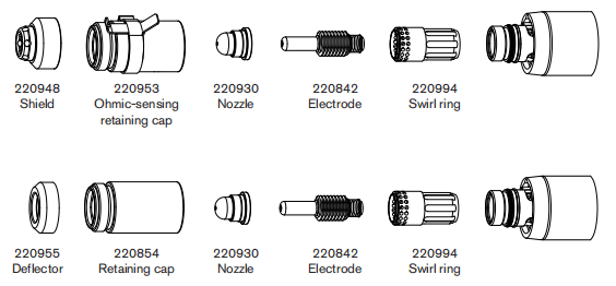
Finecut (Mild Steel)
| Air fiow rate -slpm/scth | |
| Hot | 181/384 |
| Cold | 191/404 |
Metric
| Material Thickness | Current | Torch-to-Work Distance | Inital Pierce Height | Pierce Delay Time | Recommended | ||
| Cut Speed | Voltage | ||||||
| mm | A | mm | mm | % | seconds | (mm/min) | Volts |
| 0.5 | 40 | 1.5 | 2.25 | 150 | 0.0 | 8250 | 78 |
| 0.6 | 8250 | 78 | |||||
| 0.8 | 0.1 | 8250 | 78 | ||||
| 1 | 45 | 0.2 | 8250 | 78 | |||
| 1.5 | 0.4 | 6400 | 78 | ||||
| 2 | 4800 | 78 | |||||
| 3 | 0.5 | 2750 | 78 | ||||
| 4 | 0.6 | 1900 | 78 | ||||
English
| Material Thickness | Current | Torch-to-Work Distance | Inital Pierce Height | Pierce Delay Time | Recommended | ||
| Cut Speed | Voltage | ||||||
| inches | A | inches | inches | % | seconds | ipm | Volts |
| 26GA | 40 | 0.06 | 0.09 | 150 | 0.0 | 325 | 78 |
| 24GA | 325 | 78 | |||||
| 22GA | 0.1 | 325 | 78 | ||||
| 20GA | 325 | 78 | |||||
| 18GA | 45 | 0.2 | 325 | 78 | |||
| 16GA | 0.4 | 250 | 78 | ||||
| 14GA | 200 | 78 | |||||
| 12GA | 0.5 | 120 | 78 | ||||
| 10GA | 95 | 78 | |||||
Finecut (Stainless Steel)
| Air fiow rate -slpm/scth | |
| Hot | 181/384 |
| Cold | 191/404 |
Metric
| Material Thickness | Current | Torch-to-Work Distance | Inital Pierce Height | Pierce Delay Time | Recommended | ||
| Cut Speed | Voltage | ||||||
| mm | A | mm | mm | % | seconds | (mm/min) | Volts |
| 0.5 | 40 | 0.5 | 2.0 | 400 | 0.0 | 8250 | 68 |
| 0.6 | 8250 | 68 | |||||
| 0.8 | 0.1 | 8250 | 68 | ||||
| 1 | 45 | 0.15 | 8250 | 68 | |||
| 1.5 | 0.4 | 6150 | 70 | ||||
| 2 | 4800 | 71 | |||||
| 3 | 0.5 | 2550 | 80 | ||||
| 4 | 0.6 | 1050 | 80 | ||||
English
| Material Thickness | Current | Torch-to-Work Distance | Inital Pierce Height | Pierce Delay Time | Recommended | ||
| Cut Speed | Voltage | ||||||
| inches | A | inches | inches | % | seconds | ipm | Volts |
| 26GA | 40 | 0.02 | 0.08 | 400 | 0.0 | 325 | 68 |
| 24GA | 325 | 68 | |||||
| 22GA | 0.1 | 325 | 68 | ||||
| 20GA | 325 | 68 | |||||
| 18GA | 45 | 0.2 | 325 | 68 | |||
| 16GA | 0.4 | 240 | 70 | ||||
| 14GA | 200 | 70 | |||||
| 12GA | 0.5 | 120 | 80 | ||||
| 10GA | 0.6 | 75 | 80 | ||||
Low Speed Finecut (Mild Steel)
| Air fiow rate -slpm/scth | |
| Hot | 181/384 |
| Cold | 191/404 |
Metric
| Material Thickness | Current | Torch-to-Work Distance | Inital Pierce Height | Pierce Delay Time | Recommended | ||
| Cut Speed | Voltage | ||||||
| mm | A | mm | mm | % | seconds | (mm/min) | Volts |
| 0.5 | 30 | 1.5 | 2.25 | 150 | 0.0 | 3800 | 69 |
| 0.6 | 3800 | 68 | |||||
| 0.8 | 0.1 | 3800 | 70 | ||||
| 1 | 40 | 0.2 | 3800 | 72 | |||
| 1.5 | 0.4 | 3800 | 75 | ||||
| 2 | 45 | 3700 | 76 | ||||
| 3 | 0.5 | 2750 | 78 | ||||
| 4 | 1900 | 78 | |||||
English
| Material Thickness | Current | Torch-to-Work Distance | Inital Pierce Height | Pierce Delay Time | Recommended | ||
| Cut Speed | Voltage | ||||||
| inches | A | inches | inches | % | seconds | ipm | Volts |
| 26GA | 30 | 0.06 | 0.09 | 150 | 0.0 | 150 | 78 |
| 24GA | 150 | 68 | |||||
| 22GA | 0.1 | 150 | 70 | ||||
| 20GA | 150 | 71 | |||||
| 18GA | 40 | 0.2 | 150 | 73 | |||
| 16GA | 0.4 | 150 | 75 | ||||
| 14GA | 45 | 150 | 76 | ||||
| 12GA | 0.5 | 120 | 78 | ||||
| 10GA | 95 | 78 | |||||
Low Speed Finecut (Stainless Steel)
| Air fiow rate -slpm/scth | |
| Hot | 181/384 |
| Cold | 191/404 |
Metric
| Material Thickness | Current | Torch-to-Work Distance | Inital Pierce Height | Pierce Delay Time | Recommended | ||
| Cut Speed | Voltage | ||||||
| mm | A | mm | mm | % | seconds | (mm/min) | Volts |
| 0.5 | 30 | 0.5 | 2.0 | 400 | 0.0 | 3800 | 69 |
| 0.6 | 3800 | 69 | |||||
| 0.8 | 0.1 | 3800 | 69 | ||||
| 1 | 40 | 0.15 | 3800 | 69 | |||
| 1.5 | 0.4 | 2900 | 69 | ||||
| 2 | 45 | 2750 | 69 | ||||
| 3 | 0.5 | 2550 | 80 | ||||
| 4 | 0.6 | 1050 | 80 | ||||
English
| Material Thickness | Current | Torch-to-Work Distance | Inital Pierce Height | Pierce Delay Time | Recommended | ||
| Cut Speed | Voltage | ||||||
| inches | A | inches | inches | % | seconds | ipm | Volts |
| 26GA | 30 | 0.02 | 0.08 | 400 | 0.0 | 150 | 69 |
| 24GA | 150 | 69 | |||||
| 22GA | 0.1 | 150 | 69 | ||||
| 20GA | 150 | 69 | |||||
| 18GA | 40 | 0.2 | 145 | 69 | |||
| 16GA | 0.4 | 115 | 69 | ||||
| 14GA | 45 | 110 | 69 | ||||
| 12GA | 0.5 | 120 | 80 | ||||
| 10GA | 0.6 | 75 | 80 | ||||
105A unshielded consumables
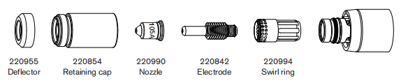
105A unshielded cutting(Mild Steel)
| Air fiow rate -slpm/scth | |
| Hot | 217/460 |
| Cold | 250/530 |
Metric
| Material Thickness | Torch-to-Work Distance | Inital Pierce Height | Pierce Delay Time | Best Quality | Production Settings | |||
| Cut Speed | Voltage | Cut Speed | Voltage | |||||
| mm | mm | mm | % | seconds | (mm/min) | Volts | (mm/min) | Volts |
| 6 | 4.6 | 9.2 | 200.0 | 0.5 | 4040 | 148 | 4980 | 145 |
| 8 | 3160 | 149 | 3770 | 145 | ||||
| 10 | 2350 | 150 | 2700 | 145 | ||||
| 12 | 1700 | 153 | 2080 | 147 | ||||
| 16 | 0.6 | 980 | 155 | 1200 | 152 | |||
| 20 | 1.0 | 742 | 155 | 940 | 154 | |||
| 25 | Edge Start | 500 | 159 | 580 | 159 | |||
| 30 | 300 | 161 | 370 | 160 | ||||
| 32 | 260 | 169 | 270 | 167 | ||||
| 35 | 320 | 164 | 350 | 163 | ||||
| 40 | 160 | 176 | 190 | 172 | ||||
English
| Material Thickness | Torch-to-Work Distance | Inital Pierce Height | Pierce Delay Time | Recommended | Production Settings | |||
| Cut Speed | Voltage | Cut Speed | Voltage | |||||
| inches | inches | inches | % | seconds | ipm | Volts | ipm | Volts |
| 1/4 | 0.18 | 0.36 | 200 | 0.5 | 153 | 148 | 188 | 145 |
| 3/8 | 91 | 150 | 112 | 145 | ||||
| 1/2 | 62 | 153 | 76 | 148 | ||||
| 5/8 | 0.6 | 39 | 155 | 48 | 152 | |||
| 3/4 | 1.0 | 31 | 155 | 40 | 153 | |||
| 7/8 | 1.25 | 25 | 156 | 30 | 158 | |||
| 1 | Edge Start | 19 | 160 | 22 | 159 | |||
| 1-1/8 | 14 | 161 | 17 | 160 | ||||
| 1-1/4 | 13 | 164 | 14 | 163 | ||||
105A unshielded cutting(Stainless Steel)
| Air fiow rate -slpm/scth | |
| Hot | 217/460 |
| Cold | 250/530 |
Metric
| Material Thickness | Torch-to-Work Distance | Inital Pierce Height | Pierce Delay Time | Best Quality | Production Settings | |||
| Cut Speed | Voltage | Cut Speed | Voltage | |||||
| mm | mm | mm | % | seconds | (mm/min) | Volts | (mm/min) | Volts |
| 6 | 4.6 | 9.2 | 200.0 | 0.5 | 4970 | 145 | 6120 | 142 |
| 8 | 3420 | 147 | 4210 | 144 | ||||
| 10 | 2090 | 149 | 2570 | 146 | ||||
| 12 | 1410 | 151 | 1740 | 149 | ||||
| 16 | 0.75 | 880 | 153 | 1080 | 151 | |||
| 20 | 1.0 | 660 | 156 | 800 | 155 | |||
| 25 | Edge Start | 420 | 159 | 500 | 159 | |||
| 30 | 330 | 162 | 370 | 161 | ||||
| 32 | 300 | 163 | 320 | 162 | ||||
English
| Material Thickness | Torch-to-Work Distance | Inital Pierce Height | Pierce Delay Time | Recommended | Production Settings | |||
| Cut Speed | Voltage | Cut Speed | Voltage | |||||
| inches | inches | inches | % | seconds | ipm | Volts | ipm | Volts |
| 1/4 | 0.18 | 0.36 | 200 | 0.5 | 185 | 145 | 228 | 142 |
| 3/8 | 88 | 149 | 108 | 145 | ||||
| 1/2 | 52 | 151 | 64 | 149 | ||||
| 5/8 | 0.8 | 35 | 153 | 43 | 151 | |||
| 3/4 | 1.0 | 28 | 155 | 34 | 154 | |||
| 7/8 | Edge Start | 22 | 157 | 26 | 157 | |||
| 1 | 16 | 159 | 19 | 159 | ||||
| 1-1/8 | 14 | 161 | 16 | 161 | ||||
105A unshielded cutting(Aluminum)
| Air fiow rate -slpm/scth | |
| Hot | 217/460 |
| Cold | 250/530 |
Metric
| Material Thickness | Torch-to-Work Distance | Inital Pierce Height | Pierce Delay Time | Best Quality | Production Settings | |||
| Cut Speed | Voltage | Cut Speed | Voltage | |||||
| mm | mm | mm | % | seconds | (mm/min) | Volts | (mm/min) | Volts |
| 6 | 4.6 | 9.2 | 200.0 | 0.5 | 5840 | 148 | 7170 | 149 |
| 8 | 0.75 | 4110 | 152 | 5060 | 151 | |||
| 10 | 2670 | 154 | 3580 | 153 | ||||
| 12 | 1.0 | 2090 | 155 | 2450 | 154 | |||
| 16 | 1330 | 160 | 1660 | 158 | ||||
| 20 | Edge Start | 980 | 163 | 1190 | 162 | |||
| 25 | 660 | 167 | 770 | 167 | ||||
| 30 | 500 | 170 | 590 | 169 | ||||
| 32 | 450 | 171 | 520 | 170 | ||||
English
| Material Thickness | Torch-to-Work Distance | Inital Pierce Height | Pierce Delay Time | Recommended | Production Settings | |||
| Cut Speed | Voltage | Cut Speed | Voltage | |||||
| inches | inches | inches | % | seconds | ipm | Volts | ipm | Volts |
| 1/4 | 0.18 | 0.36 | 200 | 0.5 | 218 | 149 | 268 | 149 |
| 3/8 | 0.75 | 110 | 154 | 136 | 153 | |||
| 1/2 | 1.0 | 77 | 156 | 91 | 155 | |||
| 5/8 | 51 | 160 | 66 | 158 | ||||
| 3/4 | 1.25 | 41 | 162 | 50 | 161 | |||
| 7/8 | Edge Start | 33 | 165 | 40 | 164 | |||
| 1 | 25 | 167 | 29 | 167 | ||||
| 1-1/8 | 20 | 169 | 25 | 169 | ||||
85A Unshielded Consumables
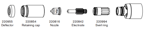
85A Unshielded Cutting (Mild Steel)
| Air fiow rate -slpm/scth | |
| Hot | 194/412 |
| Cold | 236/500 |
Metric
| Material Thickness | Torch-to-Work Distance | Inital Pierce Height | Pierce Delay Time | Best Quality | Production Settings | |||
| Cut Speed | Voltage | Cut Speed | Voltage | |||||
| mm | mm | mm | % | seconds | (mm/min) | Volts | (mm/min) | Volts |
| 2 | 2.0 | 5.0 | 250 | 0.0 | 7150 | 117 | 10400 | 116 |
| 3 | 0.1 | 6240 | 118 | 9000 | 117 | |||
| 4 | 0.2 | 5250 | 118 | 7200 | 117 | |||
| 6 | 0.5 | 3450 | 120 | 4400 | 119 | |||
| 8 | 2400 | 121 | 3100 | 121 | ||||
| 10 | 1560 | 123 | 2070 | 122 | ||||
| 12 | 6.0 | 300 | 0.7 | 1200 | 126 | 1600 | 124 | |
| 16 | Edge Start | 820 | 132 | 930 | 128 | |||
| 20 | 540 | 137 | 640 | 132 | ||||
| 25 | 320 | 143 | 400 | 137 | ||||
English
| Material Thickness | Torch-to-Work Distance | Inital Pierce Height | Pierce Delay Time | Recommended | Production Settings | |||
| Cut Speed | Voltage | Cut Speed | Voltage | |||||
| inches | inches | inches | % | seconds | ipm | Volts | ipm | Volts |
| 14GA | 0.08 | 0.20 | 250 | 0.1 | 280 | 117 | 416 | 116 |
| 10GA | 0.2 | 230 | 118 | 328 | 117 | |||
| 3/16 | 175 | 119 | 220 | 118 | ||||
| 1/4 | 0.5 | 125 | 120 | 160 | 119 | |||
| 3/8 | 65 | 122 | 86 | 122 | ||||
| 1/2 | 0.24 | 300 | 0.6 | 42 | 127 | 56 | 125 | |
| 5/8 | Edge Start | 33 | 131 | 37 | 128 | |||
| 3/4 | 23 | 136 | 27 | 131 | ||||
| 7/8 | 18 | 140 | 21 | 134 | ||||
| 1 | 12 | 144 | 15 | 138 | ||||
85A Unshielded Cutting (Stainless Steel)
| Air fiow rate -slpm/scth | |
| Hot | 194/412 |
| Cold | 236/500 |
Metric
| Material Thickness | Torch-to-Work Distance | Inital Pierce Height | Pierce Delay Time | Best Quality | Production Settings | |||
| Cut Speed | Voltage | Cut Speed | Voltage | |||||
| mm | mm | mm | % | seconds | (mm/min) | Volts | (mm/min) | Volts |
| 2 | 2.0 | 5.0 | 250 | 0.1 | 8550 | 117 | 11300 | 116 |
| 3 | 7000 | 118 | 9660 | 117 | ||||
| 4 | 0.2 | 5600 | 118 | 7800 | 118 | |||
| 6 | 0.5 | 3400 | 120 | 4570 | 121 | |||
| 8 | 2250 | 121 | 2970 | 122 | ||||
| 10 | 6.0 | 300 | 0.5 | 1430 | 123 | 1840 | 124 | |
| 12 | 0.7 | 1000 | 129 | 1340 | 128 | |||
| 16 | Edge Start | 650 | 134 | 730 | 133 | |||
| 20 | 360 | 138 | 570 | 137 | ||||
English
| Material Thickness | Torch-to-Work Distance | Inital Pierce Height | Pierce Delay Time | Recommended | Production Settings | |||
| Cut Speed | Voltage | Cut Speed | Voltage | |||||
| inches | inches | inches | % | seconds | ipm | Volts | ipm | Volts |
| 14GA | 0.08 | 0.20 | 250 | 0.1 | 340 | 117 | 452 | 116 |
| 10GA | 0.2 | 250 | 118 | 352 | 118 | |||
| 3/16 | 180 | 119 | 249 | 119 | ||||
| 1/4 | 0.5 | 120 | 120 | 160 | 121 | |||
| 3/8 | 60 | 122 | 77 | 123 | ||||
| 1/2 | 0.24 | 300 | 0.6 | 35 | 131 | 46 | 129 | |
| 5/8 | Edge Start | 26 | 134 | 29 | 133 | |||
| 3/4 | 17 | 137 | 24 | 136 | ||||
85A Unshielded Cutting (Aluminum)
| Air fiow rate -slpm/scth | |
| Hot | 194/412 |
| Cold | 236/500 |
Metric
| Material Thickness | Torch-to-Work Distance | Inital Pierce Height | Pierce Delay Time | Best Quality | Production Settings | |||
| Cut Speed | Voltage | Cut Speed | Voltage | |||||
| mm | mm | mm | % | seconds | (mm/min) | Volts | (mm/min) | Volts |
| 2 | 2.0 | 5.0 | 250 | 0.1 | 8700 | 118 | 11200 | 118 |
| 3 | 7350 | 120 | 9600 | 119 | ||||
| 4 | 0.2 | 6000 | 122 | 8100 | 120 | |||
| 6 | 0.5 | 3300 | 125 | 4930 | 122 | |||
| 8 | 2350 | 127 | 3250 | 124 | ||||
| 10 | 6.0 | 300 | 0.5 | 1800 | 128 | 2140 | 127 | |
| 12 | 0.7 | 1300 | 138 | 1720 | 130 | |||
| 16 | Edge Start | 840 | 139 | 1130 | 134 | |||
| 20 | 470 | 144 | 700 | 138 | ||||
English
| Material Thickness | Torch-to-Work Distance | Inital Pierce Height | Pierce Delay Time | Recommended | Production Settings | |||
| Cut Speed | Voltage | Cut Speed | Voltage | |||||
| inches | inches | inches | % | seconds | ipm | Volts | ipm | Volts |
| 1/8 | 0.08 | 0.20 | 250 | 0.2 | 280 | 120 | 368 | 119 |
| 3/16 | 200 | 123 | 271 | 120 | ||||
| 1/4 | 0.5 | 110 | 126 | 172 | 122 | |||
| 3/8 | 75 | 127 | 88 | 126 | ||||
| 1/2 | 0.24 | 300 | 0.6 | 45 | 135 | 62 | 131 | |
| 5/8 | Edge Start | 34 | 139 | 45 | 134 | |||
| 3/4 | 22 | 143 | 32 | 137 | ||||
65A Unshielded Consumables
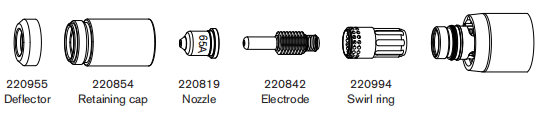
65A Unshielded Cutting (Mild Steel)
| Air fiow rate -slpm/scth | |
| Hot | 175/370 |
| Cold | 209/443 |
Metric
| Material Thickness | Torch-to-Work Distance | Inital Pierce Height | Pierce Delay Time | Best Quality | Production Settings | |||
| Cut Speed | Voltage | Cut Speed | Voltage | |||||
| mm | mm | mm | % | seconds | (mm/min) | Volts | (mm/min) | Volts |
| 2 | 2.0 | 5.0 | 250 | 0.1 | 6050 | 117 | 7340 | 117 |
| 3 | 0.2 | 5200 | 118 | 6330 | 118 | |||
| 4 | 0.5 | 4250 | 118 | 5250 | 118 | |||
| 6 | 2550 | 120 | 3560 | 120 | ||||
| 8 | 1620 | 123 | 2330 | 121 | ||||
| 10 | 6.0 | 300 | 0.7 | 970 | 127 | 1500 | 122 | |
| 12 | Edge Start | 760 | 129 | 1140 | 124 | |||
| 16 | 500 | 134 | 650 | 129 | ||||
| 20 | 280 | 138 | 400 | 133 | ||||
English
| Material Thickness | Torch-to-Work Distance | Inital Pierce Height | Pierce Delay Time | Recommended | Production Settings | |||
| Cut Speed | Voltage | Cut Speed | Voltage | |||||
| inches | inches | inches | % | seconds | ipm | Volts | ipm | Volts |
| 16GA | 0.08 | 0.20 | 250 | 0.1 | 255 | 116 | 308 | 117 |
| 10GA | 190 | 118 | 232 | 118 | ||||
| 3/16 | 0.2 | 135 | 119 | 172 | 119 | |||
| 1/4 | 0.5 | 90 | 120 | 116 | 120 | |||
| 3/8 | 0.24 | 300 | 0.7 | 40 | 126 | 62 | 122 | |
| 1/2 | Edge Start | 27 | 130 | 40 | 125 | |||
| 5/8 | 20 | 134 | 26 | 129 | ||||
| 3/4 | 13 | 137 | 18 | 132 | ||||
85A Unshielded Cutting (Stainless Steel)
| Air fiow rate -slpm/scth | |
| Hot | 175/370 |
| Cold | 209/443 |
Metric
| Material Thickness | Torch-to-Work Distance | Inital Pierce Height | Pierce Delay Time | Best Quality | Production Settings | |||
| Cut Speed | Voltage | Cut Speed | Voltage | |||||
| mm | mm | mm | % | seconds | (mm/min) | Volts | (mm/min) | Volts |
| 2 | 2.0 | 5.0 | 250 | 0.1 | 7950 | 117 | 10300 | 117 |
| 3 | 0.2 | 6600 | 118 | 8500 | 118 | |||
| 4 | 0.5 | 5050 | 119 | 6500 | 118 | |||
| 6 | 2300 | 121 | 3070 | 120 | ||||
| 8 | 0.7 | 1620 | 123 | 1900 | 121 | |||
| 10 | 6.0 | 300 | 0.7 | 970 | 126 | 1250 | 122 | |
| 12 | Edge Start | 710 | 130 | 925 | 127 | |||
| 16 | 430 | 135 | 500 | 133 | ||||
English
| Material Thickness | Torch-to-Work Distance | Inital Pierce Height | Pierce Delay Time | Recommended | Production Settings | |||
| Cut Speed | Voltage | Cut Speed | Voltage | |||||
| inches | inches | inches | % | seconds | ipm | Volts | ipm | Volts |
| 16GA | 0.08 | 0.20 | 250 | 0.1 | 340 | 116 | 437 | 115 |
| 10GA | 235 | 118 | 304 | 118 | ||||
| 3/16 | 0.2 | 150 | 119 | 172 | 121 | |||
| 1/4 | 0.5 | 75 | 120 | 116 | 120 | |||
| 3/8 | 0.24 | 300 | 0.7 | 38 | 126 | 52 | 122 | |
| 1/2 | Edge Start | 25 | 132 | 32 | 129 | |||
| 5/8 | 17 | 135 | 20 | 133 | ||||
85A Unshielded Cutting (Aluminum)
| Air fiow rate -slpm/scth | |
| Hot | 175/370 |
| Cold | 209/443 |
Metric
| Material Thickness | Torch-to-Work Distance | Inital Pierce Height | Pierce Delay Time | Best Quality | Production Settings | |||
| Cut Speed | Voltage | Cut Speed | Voltage | |||||
| mm | mm | mm | % | seconds | (mm/min) | Volts | (mm/min) | Volts |
| 2 | 2.0 | 5.0 | 250 | 0.1 | 7750 | 123 | 11300 | 122 |
| 3 | 0.2 | 6550 | 124 | 9500 | 123 | |||
| 4 | 0.5 | 5400 | 125 | 7640 | 124 | |||
| 6 | 3000 | 127 | 3900 | 126 | ||||
| 8 | 0.7 | 1800 | 130 | 2460 | 127 | |||
| 10 | 6.0 | 300 | 0.7 | 1100 | 133 | 1640 | 129 | |
| 12 | Edge Start | 900 | 135 | 1250 | 133 | |||
| 16 | 600 | 139 | 700 | 136 | ||||
English
| Material Thickness | Torch-to-Work Distance | Inital Pierce Height | Pierce Delay Time | Recommended | Production Settings | |||
| Cut Speed | Voltage | Cut Speed | Voltage | |||||
| inches | inches | inches | % | seconds | ipm | Volts | ipm | Volts |
| 1/16 | 0.08 | 0.20 | 250 | 0.1 | 325 | 116 | 437 | 122 |
| 1/8 | 250 | 118 | 304 | 123 | ||||
| 3/16 | 175 | 119 | 172 | 124 | ||||
| 1/4 | 0.5 | 100 | 120 | 116 | 126 | |||
| 3/8 | 0.24 | 300 | 0.7 | 45 | 126 | 52 | 128 | |
| 1/2 | Edge Start | 32 | 132 | 32 | 134 | |||
| 5/8 | 24 | 135 | 20 | 136 | ||||
45A Unshielded Consumables
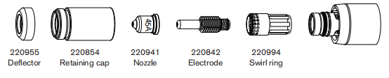
45A Unshielded Cutting (Mild Steel)
| Air fiow rate -slpm/scth | |
| Hot | 177/376 |
| Cold | 201/427 |
Metric
| Material Thickness | Torch-to-Work Distance | Inital Pierce Height | Pierce Delay Time | Best Quality | Production Settings | |||
| Cut Speed | Voltage | Cut Speed | Voltage | |||||
| mm | mm | mm | % | seconds | (mm/min) | Volts | (mm/min) | Volts |
| 0.5 | 1.5 | 3.8 | 250 | 0.0 | 9000 | 120 | 12500 | 120 |
| 1 | 9000 | 120 | 10800 | 121 | ||||
| 1.5 | 0.1 | 7700 | 120 | 10200 | 121 | |||
| 2 | 0.3 | 6150 | 119 | 7800 | 122 | |||
| 3 | 0.4 | 3950 | 121 | 4900 | 123 | |||
| 4 | 2350 | 123 | 3560 | 124 | ||||
| 6 | 0.5 | 1400 | 126 | 2050 | 124 | |||
English
| Material Thickness | Torch-to-Work Distance | Inital Pierce Height | Pierce Delay Time | Recommended | Production Settings | |||
| Cut Speed | Voltage | Cut Speed | Voltage | |||||
| inches | inches | inches | % | seconds | ipm | Volts | ipm | Volts |
| 26GA | 0.06 | 0.15 | 250 | 0.0 | 350 | 120 | 500 | 120 |
| 22GA | 350 | 120 | 450 | 120 | ||||
| 18GA | 0.1 | 350 | 119 | 400 | 121 | |||
| 16GA | 300 | 121 | 400 | 121 | ||||
| 14GA | 0.2 | 250 | 119 | 320 | 122 | |||
| 12GA | 0.4 | 200 | 120 | 216 | 123 | |||
| 10GA | 100 | 123 | 164 | 124 | ||||
| 3/16 | 0.5 | 85 | 122 | 108 | 124 | |||
| 1/4 | 0.6 | 48 | 127 | 73 | 124 | |||
45A Unshielded Cutting (Stainless Steel)
| Air fiow rate -slpm/scth | |
| Hot | 177/376 |
| Cold | 201/427 |
Metric
| Material Thickness | Torch-to-Work Distance | Inital Pierce Height | Pierce Delay Time | Best Quality | Production Settings | |||
| Cut Speed | Voltage | Cut Speed | Voltage | |||||
| mm | mm | mm | % | seconds | (mm/min) | Volts | (mm/min) | Volts |
| 0.5 | 1.5 | 3.8 | 250 | 0.0 | 9000 | 121 | 12500 | 119 |
| 1 | 9000 | 121 | 10800 | 119 | ||||
| 1.5 | 0.1 | 9000 | 121 | 10200 | 120 | |||
| 2 | 0.3 | 6000 | 122 | 7800 | 120 | |||
| 3 | 0.4 | 3250 | 122 | 4900 | 122 | |||
| 4 | 1900 | 128 | 3560 | 124 | ||||
| 6 | 0.5 | 700 | 130 | 1450 | 124 | |||
English
| Material Thickness | Torch-to-Work Distance | Inital Pierce Height | Pierce Delay Time | Recommended | Production Settings | |||
| Cut Speed | Voltage | Cut Speed | Voltage | |||||
| inches | inches | inches | % | seconds | ipm | Volts | ipm | Volts |
| 26GA | 0.02 | 0.08 | 400 | 0.0 | 350 | 120 | 500 | 119 |
| 22GA | 350 | 120 | 450 | 119 | ||||
| 18GA | 0.1 | 350 | 119 | 400 | 119 | |||
| 16GA | 300 | 121 | 400 | 120 | ||||
| 14GA | 0.06 | 0.15 | 250 | 0.2 | 250 | 119 | 320 | 120 |
| 12GA | 0.4 | 200 | 120 | 216 | 120 | |||
| 10GA | 100 | 123 | 164 | 121 | ||||
| 3/16 | 0.5 | 42 | 131 | 88 | 123 | |||
| 1/4 | 0.6 | 25 | 130 | 48 | 124 | |||
45A Unshielded Cutting (Aluminum)
| Air fiow rate -slpm/scth | |
| Hot | 177/376 |
| Cold | 201/427 |
Metric
| Material Thickness | Torch-to-Work Distance | Inital Pierce Height | Pierce Delay Time | Best Quality | Production Settings | |||
| Cut Speed | Voltage | Cut Speed | Voltage | |||||
| mm | mm | mm | % | seconds | (mm/min) | Volts | (mm/min) | Volts |
| 1 | 1.5 | 3.8 | 250 | 0.0 | 7400 | 126 | 11000 | 119 |
| 2 | 0.1 | 4400 | 127 | 9200 | 119 | |||
| 3 | 0.2 | 2800 | 129 | 10200 | 120 | |||
| 4 | 0.4 | 2100 | 132 | 7800 | 126 | |||
| 6 | 0.5 | 1050 | 135 | 2250 | 127 | |||
English
| Material Thickness | Torch-to-Work Distance | Inital Pierce Height | Pierce Delay Time | Recommended | Production Settings | |||
| Cut Speed | Voltage | Cut Speed | Voltage | |||||
| inches | inches | inches | % | seconds | ipm | Volts | ipm | Volts |
| 1/32 | 0.06 | 0.15 | 250 | 0.0 | 325 | 120 | 500 | 121 |
| 1/16 | 0.1 | 200 | 120 | 450 | 122 | |||
| 3/32 | 0.2 | 150 | 119 | 400 | 124 | |||
| 1/8 | 0.4 | 100 | 130 | 224 | 125 | |||
| 1/4 | 0.5 | 36 | 136 | 72 | 127 | |||
Section 7 Mechanized Cutting
Connecting an optional remote-start pendant
Powermax105 configurations with a Duramax machine torch caninclude an optional remote-start pendant. • Part number 128650:7.6m(25feet) • Part number 128651:15.2m(50feet) • Part number 128652:22.9m(75 feet)If your power supply has the optional machine interface receptacle on the rear of the power supply, remove the receptacle cover and plug the Hypertherm remote-start pendant into the receptacle. Note:The remote-start pendant is for use only with a machine torch. It will not operate if a handheld torch is installed.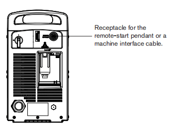
Connecting an optional machine interface cable
The Powermax power supply may be equipped with a factory-installed (or user-installed) five-position voltage divider board. The bult-in voltage divider provides a scaled down arc voltage of 20:1,21.1:1,30:1,40:1,or 50:1(maximum output of 15 V). An optional receptacle on the rear of the power supply (see the previous page) provides access to the scaled down arc voltage and signals for arc transfer and plasma start.Note:The factory presets the voltage divider to 50:1.To change the voltage divider to adifferent setting, referto page 7-6 Setting the five-position voltage divider.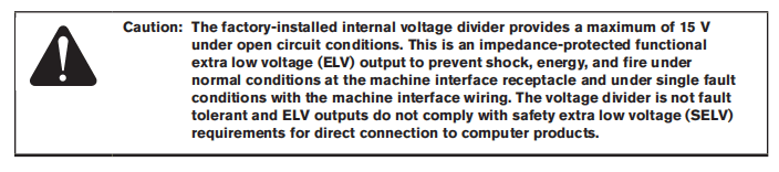
Hypertherm offers several choices of machine interface cables for the Powermax105: • To use the buit-in voltage divider that provides ascaled down arc votage in addition to signals for arc transfer and plasma start: Use part number 228350 (7.6m, 25 feet) or 228351 (15.2 m 50 feet) for wires terminated with spade connectors.Use part number 123896 (15.2m, 50 feet) for a cable terminated with a D-sub connector. (Compatible with Hypertherm products, such as Edgel T and Sensor”PHC) • To use signals for arc transfer and plasma start only,use either part number 023206(7.6m,25feet) or part number 023279(15.2m,50feeb). These cables have spade connectors as shown below. Refer to page 7-5 Machine interface pinout for receptacle pinout infomation.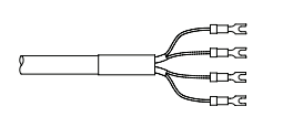
Note:The cover on the machine interface receptacle prevents dust and moisture from damaging the receptacle when not in use. This cover should be replaced if damaged or lost (part number 127204). See the Parts section for more infomation.Installation of the machine interface cable must be performed by a qualified service technician. To install a machine interface cable:1. Turn OFF the power and disconnect the power cord.2 Remove the machine interface receptacle’s cover fom the rear of the power supply.3.Connect the Hypertherm machine interface cable to the power supply.4. If you are using a cable with aD-sub connector on the other end, plug it into the appropriate pin connector on the torch height controller or CNC. Secure it with the screws on the D-sub connector.If you are using a cable with wires and spade connectors on the other end, terminate the machine interface cable inside the electrical enclosure of the torch height controller or CNC controller to prevent unauthorized access to the connections after installation. Verify that the connections are correct and that all live parts are endosed and protected before operating the equipment.Note:The integration of Hyperthem equipment and customer-supplied equipmentincluding interconnecting cords and cables, if not listed and certified as a system,is subject to inspection by local authorities at the final installation site. The connector sockets for each type of signal available through the machine interface cable are shown in the figure on the next page. The table provides details about each signal type.
Machine interface pinout
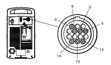
Refer to the following table when connecting the Powermax 105 to a torch height controller or CNC controller with a machine interface cable.
| Signal | Type | Notes | Connector sockets | External cable wire |
| Start (start plasma) | Input | Normaly open. 18VDC open circuit woltage at START teminals. Requires dry contact closure to activate. | 3,4 | Green, black |
| Transfer (start machine motion) | Output | Nomally open. Dry contact closure when the arc transfers. 120VAC/1 A maximum at the machine interface relay. | 12,14 | Red, black |
| Ground | Ground | 13 | ||
| Voltage divider | Output | Divided arc signal of 20:1,21.1:1, 30:1,40:1,50:1(provides a maximum of 15V). | 5(-),6(+) | Black (-), white(+) |
Setting the five-position voltage divider
To change the factory preset voltage divider from 50:1to a different setting:1. Turn OFF the power supply and disconnect the power cord.2. Remove the power supply cover.3. Locate the voltage divider DIP switches on the left side of the power supply. Note:The figure below shows the default setting (50:1)with the number 4 switch up.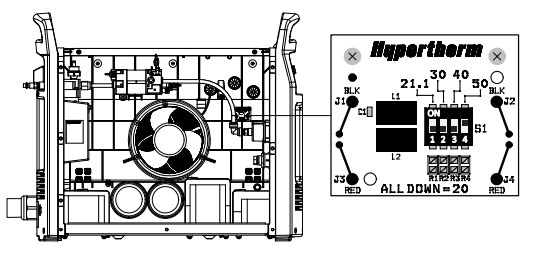
4. Set the DIP switches to one of the following settings and replace the power supply cover.
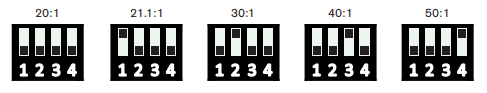
If the Hypertherm five-position voltage divider does not supply the required voltage for your application, contact your system integrator for assistance.
Accessing raw arc voltage
To access divided raw arc voltage, refer to Field Service Bulletin 807060.
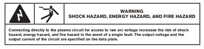
Connecting an optional RS485 serial interface cable
The RS485 serial interface connector on the back of the power supply allows you to connect an external device to your Powermax For example, you can remotely operate the Powermax withaCNC controller.The Powermax power supply must be equipped with a factory-installed (or user-installed) RS485 serial interface connector on the rear pane. The receptacle on the rear of the power supply provides access to the RS485 board inside the power supply.
Ifyour power supply is not equipped with the RS485 connector, order kit 228539,”Powermax65/85/105 RS485 board with cables”. Follow the installation instructions in the Power Supply Component Replacement section of the Service Manual.
With the RS485 connector installed:
1. Shut off the power supply.
2.Connect the RS485 cable from your external device to the receptacle on the back of the Powermax power supply.
Using the machine torch
Since the Powermax with a machine torch can be used with a wide variety of cutting tables,track bumers, pipe bevelers, and so on, you will need to refer to the manufacturer’s instructions for specifics on operating the machine torch in your configuration. However, the information in the following sections will help you optimize cut quality and maximize consumable life.
Setting up the torch and table
• Use a square to align the torch at right angles to the workpiece in two dimensions. • The torch may travel more smoothly ifyou clean, check and “tune” the cutting table’s rails and drive system
Unsteady machine motion can cause aregular, wavy pattem on the cut surface. • Ensure that the torch does not touch the workpiece during cutting. Contact with the workpiece can damage the shield and nozzle and affect the cut surface.
Understand and optimize cut quality
There are several factors to consider in cut quality: • Cut angle – The degree of angularity of the cut edge. • Dross – The molten material that solidifies on the top or bottom of the workpiece. • Straightness of the cut surface – The cut surface can be concave or convex.
The following sections explain how these factors can affect cut quality.
Cut or bevel angle
• A positive cut angle, or bevel, results when more material is removed from the top of the cut than from the bottom. • A negative cut angle results when more materialis removed from the bottom of the cut.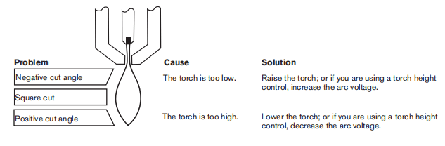
Note:The squarest cut angle will be on the right side with respect to the forward motion of the torch. The left side will always have some degree of bevel.To determine whether a cut-angle problem is being caused by the plasma system or the drive system,make a test cut and measure the angle of each side. Next, rotate the torch 90′ in its holder and repeat the process. If the angles are the same in both tests, the problem is in the drive system. If a cut-angle problem persists after “mechanical causes” have been eliminated (see page 7-8 Setting up the torch and table), check the torch-to-work distance, especially ifthe cut angles are all positive or all negative. Also consider the material being cut: if the metal is magnetized or hardened, you are more likely to experience cut angle problems.
Dross
Some amount of dross will always be present when cutting with air plasma. However, you can minimize the amount and type of dross by adjusting your system correctly for your application.Excess dross appears on the top edge of both pieces of the plate when the torch is too low (or voltage is too low when using a torch height control). Adjust the torch or adjust the voltage in small increments (5 volts or less) until the dross is reduced.Low-speed dross foms when the torch’s cutting speed is too slow and the arc angles ahead. It forms as aheavy, bubbly deposit at the bottom of the cut and can be removed easily. Increase the speed to reduce this type of dross.
High-speed dross forms when the cutting speed is too fast and the arc angles behind. it foms as athin, linear bead of solid metal attached very close to the cut. It is more firmly attached to the bottom of the cut than at low speed and is difficult to remove. To reduce high-speed dross:• Decrease the cutting speed. • Decrease the torch-to-work distance.
Piercing a workpiece using the machine torch
As with the hand torch, you can start a cut with the machine torch at the edge of the workpiece or by piercing the workpiece. Piercing may result in a shorter consumable life than with edge starts. The cut charts include a column for the recommended torch height when starting a pierce. For the Powermax105, the pierce height is generally 2.5 times the cutting height. Refer to the cut charts for specifics.The pierce delay must be long enough that the arc can pierce the material before the torch moves,but not so long that the arc “wanders” while trying to find the edge of a large hole. As consumables wear,this delay time may need to be increased. Pierce delay times given in the cut charts are based on average delay times throughout the life of the consumables.When piercing materials close to the maximum thickness for aspecific process, consider the following important factors:• Allow a lead-in distance approximately equal to the thickness of the material being pierced. For example, 20 mm (3/4 in) material requires a 20 mm lead-in. • To avoid damage to the shield from the buildup of molten material created by the pierce, do not allow the torch to descend to cut height until it has cleared the puddle of molten material. • Different material chemistries can have an adverse effect onthe pierce capablity of the system In particular, high-strength steel with a high manganese or sillicon content can reduce the maximum pierce capabilty.Hypertherm derives mild steel parameters using certified A-36 plate.
Common machine-cutting faults
The torch’s pilot arc wil initiate, but will not transfer. Causes can be: • The work cable is not making good contact with the cutting table or the cutting table is not making good contact with the workpiece. • The torch-to-work distance is too large.The workpiece is not totally penetrated, and there is excessive sparking on the top of the workpiece. Causes can be: • The metal surface is not clean of rust or paint. • The consumables are wom and need to be replaced. For optimized performance in a mechanized application, replace the nozzle and the electrode together. • The work cable is not making good contact with the cutting table or the cutting table is not making good contact with the workpiece.• The current (amperage) is settoo low. See the Machine Torch Setup section. • The cut speed is too high. See the cut charts in the Machine Torch Setup section • The metal being cut exceeds the maximum capacity for the selected amperage. See the Specifications section.Dross forms on the bottom of the cut. Causes can be: • The gas setting is incorrect • The consumables are worm and need to be replaced. For optimized performance in a mechanized application, replace the nozzle and the electrode together. • The cutting speed is not corredt. See the cut charts in the Machine Torch Setup section. • The current (amperage) is set too low. See the cut charts in the Machine Torch Setup section.The cut angle is not square. Causes can be: • The torch is not square to the work piece. • The gas setting is incorrect. • The consumables are wom and need to be replaced. For optimized performance inamechanized application, replace the nozzle and the electrode together. • The direction of the torch travel isincorrect. The high-quality cutis always on the right with respect to the forward motion of the torch. • The distance between the torch and the workpiece is not correct. • The cutting speed is not correct. See the cut charts in the Machine Torch Setup section.The consumable life is shortened. Causes can be: • The gas setting is incorrect. • The arc current, arc voltage,travel speed, and other variables are not set as recommended in the cut charts. • Firing the arc in the air (beginning or ending the cut off of the plate surface). Starting at the edge is acceptable as long as the arc makes contact with the workpiece when started. • Starting a pierce with an incorrect torch height. Refer to the cut charts for the specific initial pierce height. • The pierce time is incorrect. • The air quality is poor (oil or water in the air). • There might be afaulty pilot arc IGBT which can shorten nozzle life (refer to the troubleshooting sections in this manual, or call Technical Service)
Section 8 Troubleshooting and System Test
Controls and Indicators
The Powermax 105 controls and indicators are described in the Basic System Operations section. These figures are included for reference.
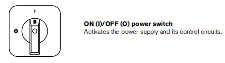
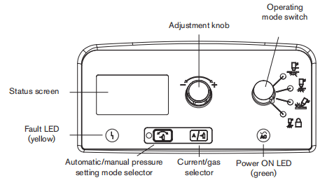
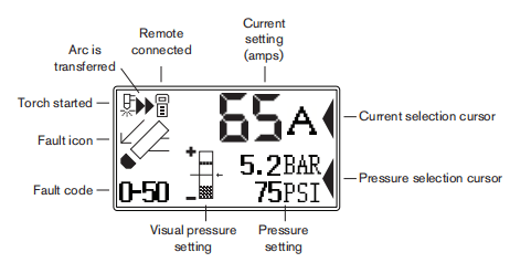
Theory of operation
General
Refer to “Sequence of operation” below and the Wining Diagrams section.
200-600 VCSA 3-phase power supply functional description
AC power enters the system through the power switch (S1) to the input diode bridge (D38) .The voltage from the bridge supplies the power factor correction (PFC) boost converter, which provides anominal 760 VDC bus voltage.The bus supplies voltage and current to the inverter and the flyback circuit (DCto DCcorverter) on the power board (PCB3). The power board provides noise suppression and spike protection. A “soft starf” is implemented via the power board resistors (RT4,RT5) and relays (K2,K3).The PFC boost converter consists of an insulated gate bipolar transistor (GBT Q11),PFCchoke, and control circuit.It provides a 760 VDC bus voltage when the input AC voltage is between 200and 540 VAC.At 600VAC, the nominal bus voltage is 840VDC.The inverter consists of a dual lGBT package (Q12),the power transformer, an output current sensor, and the control circuit. The inverter operates as a pulse-width modulated half-bridge circuit driving an isolation transformer. The output of the isolation transformer is rectified by the output bridge (D36 and D37).The output circuitry consists of 2 current sensors located on the power board, the pilot arc IGBT (Q13), and the output choke.The digital signal processor (PCB2) monitors and regulates the system’s operation and safety circuits. The amperage adjustment knob on the control board (PCB1) is used to set the output current tothe desired value:30-105 amps. The system compares the set-point to the output current by monitoring the current sensors and adjusting the output of the inverter IGBT module (Q12).
230-400 VCE,380VCCC/230-400VCE 3-phase power supply functional description
AC power enters the system through the power switch (S1) to the input diode bridge (D38) .The voltage from the bridge provides a nominal 530 to 560 vDC bus voltage. The bus supplies voltage and current to the inverter and the flyback circuit (DC to DC converter) on the power board (PCB3).
The power board provides noise suppression and spike protection. A “soft start” is implemented viathe power board resistors (RT4,RT5)and relay (K2).The PFC boost converter consists of an insulated gate bipolar transistor(IGBTQ11),PFC choke, and control circuit.It provides a nominal 760 VDC bus voltageThe inverter consists of a dual IGBT package (Q12),the power transformer, a current sensor, and the control circuit.The inverter operates as a pulse-width modulated half-bidge cirauit driving an isolation transformer. The output of the isolation transformer is rectified by the output bridge (D36 and D37).The output circuitry consists of 2 current sensors located on the power board, the pilot arclGBT (Q13), and the output choke.The digital signal processor (PCB2) monitors and regulates the system’s operation and safety circuits. The amperage adjustment knob on the control board (PCB1)is used to set the output currentto the desired value. 30-105 amps The system compares the set-point to the output current by monitoring the current sensors and adjusting the output of the inverter IGBT module. (Q12).
400 v cE,380 vcCC 3-phase power supply functional description
AC power enters the system through the power switch (S1) to the input diode bridge (D38). The voltage from the bridge provides a nominal 530to 560 VDC bus voltage. The bus supplies voltage and current to the inverter and the flyback circuit (DC to DC converter) on the power board (PCB3).
The power board provides noise suppression and spike protection. A “soft start” is implemented via the power board resistors (RT4,RT5)and relay (K2).The inverter consists of a duallGBT package (Q12),the power transformer, a current sensor, and the control circuit.The inverter operates as a pulse-width modulated half-bridge circuit driving an isolation transformer. The output of the isolation transformer is rectified by the output bridge (D36 and D37).The output circuitry consists of 2 current sensors located on the power board,the pilot arc IGBT (Q3), and the output choke.The digital signal processor (PCB2) monitors and regulates the system’s operation and safety circuits. The amperage adjustment knob on the control board (PCB1) is used to set the output current to the desired value: 30-105 amps. The system compares the set-point to the output current by monitoring the current sensors and adjusting the output of the inverter lGBT module.(Q12).
Sequence of operation
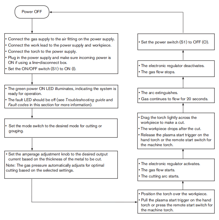
Troubleshooting preparation
The complexity of the circuits requires that service technicians have a working knowledge of inverter power supply theory. In addition to being technically qualfied, technicians must perform all testing with safety in mind. If questions or problems arise during servicing, call the Hypertherm Technical Services team listed in the front of this manual.
Test equipment
• Multimeter • IGBT(insulated gate bipolar transistor) tester (partnumber 128883)
Troubleshooting procedures and sequence
When performing the troubleshooting procedures: • Read the Safety and Compliance Manua (80669C) for detailed safety information. • Refer to the Power Supply Component Replacement section. • Refer to the Parts section. • Refer to the Wiring Diagrams section.After the problem has been located and repaired, refer to the “Sequence of operation” flow diagram in this section to test the power supply for proper operation.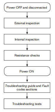
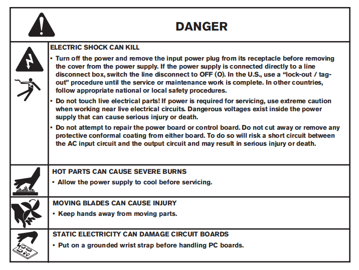
External inspection
1. Inspect the exterior of the power supply fordamage to the coverand external components, such as the power cord and plug.2. Inspect the torch and the torch lead for damage.3. Inspect the consumables for damage or wear.
Internal inspection
1. Turn OFF the power, disconnect the power cord, and disconnect the gas supply.2. Using a TORX or blade screwdriver remove the screws from the power supply cover.3. Lift the cover off the power supply.4. Remove the Mylar barrier from the power board side of the power supply. The Mylar barrier is flexible and can be bent slightly for removal. Be certain to replace the barrier when you are finished working on the power supply.5.Inspect the inside of the power supply, especially on the side with the power board. Look for broken or loose wiring connections, burn and char marks, damaged components, and so on. Repair or replace as necessary.
Initial resistance check
All resistance values must be taken with the power cord disconnected and all internal power supply wires attached.Perform the steps in Internal inspection before continuing in this section.• If resistance values are not close (t25%) to the values given in this section, isolate the problem by removing wires attached to the resistance check points or component until the problem is found. • After the problem has been located and repaired, refer to the Sequence of operation flow diagram in this section to test the power supply for proper operation.
Check the power switch
Refer to the figures and table on the following pages. 1.Wth the power disconnected and the torch removed from the power supply, set the ON/OFF switch (S1)to ON(I). 2. Check the resistance across the input leads (the leads are labeled L1,L2, andL3on the power switch).– 200-600VCSA:resistance across the input leads = 500kΩ.– 230-400VCE,380VCCC/230-400VCE, 400VCE,380VCCC:resistance across the input leads =350kΩ3. Check the resistance from the inputleads to ground to verify that it reads as open. For all power supplies, the resistance from input to ground should read as > 20MΩNote: With the power disconnected and the ON/OFF switch (S1)setto OFF (O),all circuits should read as open.The electrical values shown are ±25%
4. Check the output resistance for the values shown in the table.
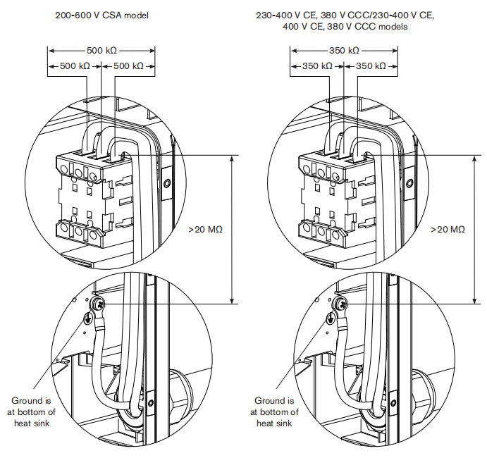
| Measure resistance from | All models |
| Work lead(J27) to nozzle(black wire) | 230kΩ |
| Work lead(J27) to electrode(red wire) | 9kΩ |
| Electrode(red wire) to nozzle(black wire) | 230kΩ |
| Output to ground | >20kΩ |
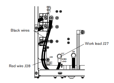
If no problems were found during the visual inspection or the initial resistance check, and the power supply still does not operate correctly, see the Troubleshooting guide.Note:Troubleshooting guide later is this section provides most probable causes and solutions. Study the system wiring diagram and understand the theory of operation before troubleshooting. Before purchasing any major replacement component, verify the problem with Hypertherm Technical Service or the nearest Hypertherm repair facility.
Hypertherm IGBT tester
Use the Hyperthem IGBT (insulated gate bipolar transistor) tester (part number 128883) as described in the following sections or assemble your own IGBT tester from the schematic diagram shown on page 8-15 Schematic for building an IGBT tester and use it to test the IGBTs.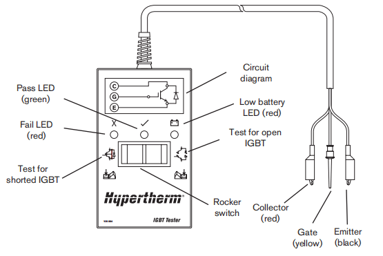
Indicator LEDs and device tests

Green “pass” LED
When iluminated, this LED indicates that thelGBT passed the test for an open IGBT when switch ispressed to the right or for a short-circuited IGBT when switch is pressed to the left.
Red “fail” LEDWhen illuminated, this LED indicates that the IGBT faled the testfor an open IGBT when switch ispressed to the right or for a short-circuited IGBT when switch is pressed to the left.
Red “low battery” LEDWhen illuminated, this LED indicates that the remaining voltage in the battery is insufficient to power the test circuitry. Replace the batery.Note: The Hypertherm IGBT tester requires a minimum of 8 Vto power its circuitry properly.
IGBT test preparation
Before testing with the Hypertherm IGBT tester, connect the colored leads to the IGBT as shown on the next page.
Note: Before an IGBT can be tested,it must be electrically isolated from all circuits. If the IGBT is installed in a power supply, remove the power board and any lead connections before testing.
The illustrations below depict three common configurations of an lGBT. Each connection on the IGBT will be labeled with an abbreviation. They may be labeled as C,E, G or 1, 2, 3 with a schematic that shows numbers and pin functions.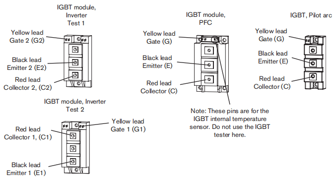
IGBT device test using the Hypertherm tester
Using the Hypertherm IGBT tester, press and hold the switch in the desired position to perform each test described in the following table.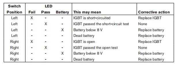
Troubleshoot the Hypertherm IGBT tester
1. Inspect the leads and the IGBT tester for damage.
2.Verifty that the battery voltage is greater than 8V.
3.Test the IGBT Tester, itself, as shown below. If the resuts do not match the table,replace the lead connections.
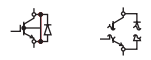
| Connect leads | Short test | Open test |
| None Red to black | Pass Fail | Fail Pass |
Schematic for building an IGBT tester
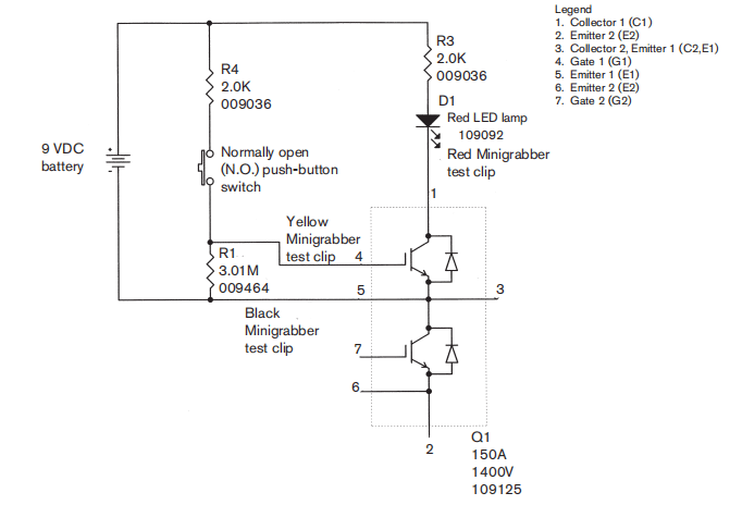
IGBT device test using a non-Hypertherm tester
The device tester shown on page 8-15 Schematic for building an IGBT tester has one LED and one push-button switch that are used in combination to perform two tests.Note: Before an IGBT can be tested,it mustbe electrically isolated from all circuits. If the lGBT is installed ina power supply, remove the power board and any lead connections before testing.1. Inspect the IGBT for cracks or black marks. If damaged,replace the IGBT.2. Verify that the 9 v battery reads greater than (>)8.0v.3.Connect the test leads as shown below.4.With the test leads connected and without pressing the push button switch, the LED should notilluminate. If the LEDis illuminated, then the IGBT is shorted. Replace the IGBT.5. With the test leads connected, press the pushbutton switch. This time, the LED should illuminate. If theLED does not illuminate, then the IGBT is open. Replace the IGBT.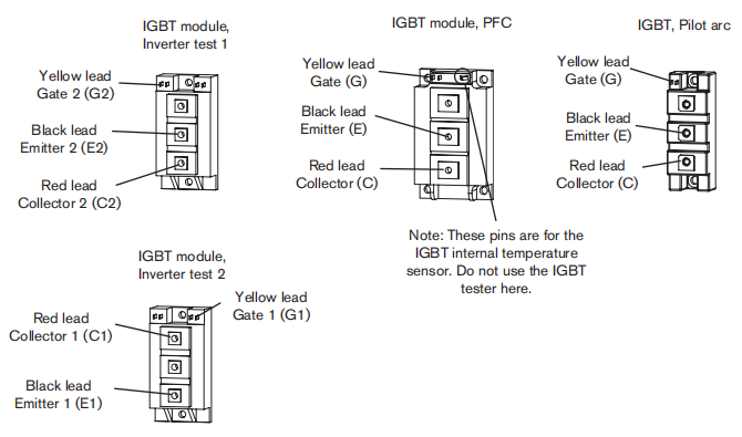
200-600V CSA power supply overview
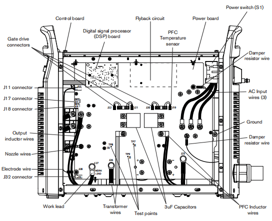
230-400V CE, 380V CCC/230-400V CE Power supply overview
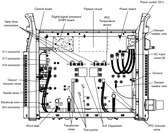
380V CCC, 400V CE Power supply overview
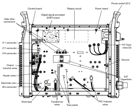
200-600V CSA power supply overview(power board removed)
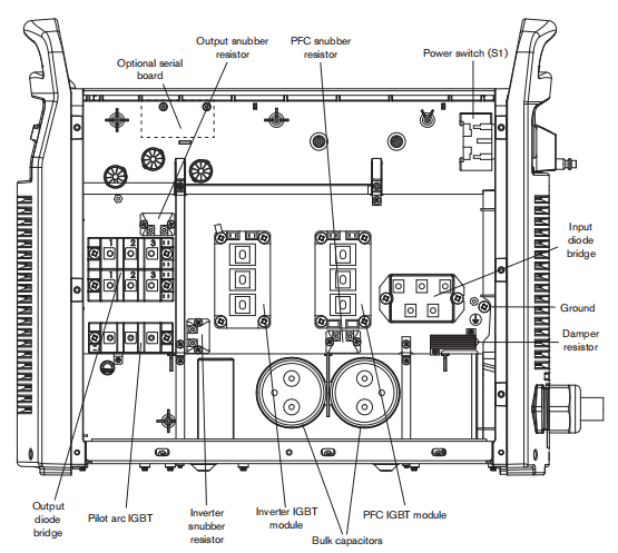
230-400V CE, 380V CCC/230-400V CE Power supply overview(power board removed)
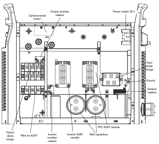
380V CCC, 400V CE Power supply overview(power board removed)
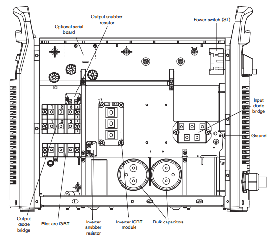
Fault codes
Fault codes displayed on the LCD screen in ‘service mode” are in the format N-nn-n. Faultcodes displayed on the LCD screen in ‘operator mode”have one fewer digit and appear in the format N-nn. The tables in this soction showall digits.The fault priority is assigned based on the fault code value: the higher the number, the higher the fault priority. Only one faut code is set at one time. fmore than one fault occus at the same time, only the fault with the highest priority is set.
Displaying the service screen
For troubleshooting faults, display the service screen by simutaneously pressing the automatic/manual and current/gas mode selectors for approximately two (2) seconds. The service screen displays.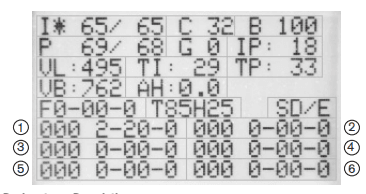
Designator
I
C
B
P
G
IP
VL
TI
TP
VB
AH
F
T
S
1-6
Description
Current set/read
LCD contrast
LCD brightness (per cent)
Pressure set/read
Gas test enable (1)disable (0)
Boost circuit current (not present on 400VCE)
Incoming AC line voltage
Inverter module temperature (C)
Boost module temperature (C), not present on 400VCE
DC bus voltage
Arc hours
Live fault code
Torch identifier (amps/H hand or M machine load length in feet)
DSP/Control board software versions
1 is the most recent fault code; 6 is the oldest fault code
Note: Fault codes beginning with zero (0-n-nn)are not recorded in the fault log.
To move the field solector () between fields, press the current gas mode selector. The asterisk indicates the selected field You can alter theL, C,B,P,and G felds by turning the adjustment knob.To toggle between (I) Curent set/read and (P) Pressure set/read, press the automatic/manual mode selector. The LED is illuminated when the Pressure set/read field is selected.To exit the service screen, simultaneously press the automatic/manual and current gas mode selectors. The operator screen displays.
Important fault icons
One of the following fault icons may appear on the LCD display in operator mode:

WarningThe system continues to operate.
FaultThe system stops cutting and is able to recover when the fault is cleared.
ErrorThe system needs service.
Performing a cold restart
Sometimes a “cold restart” cears the fault When a cold restart is recommended in one of the Solutions below, do the following:1.Power OFF the machine.2.Wait 20 seconds or until the red LED near the top of the DSP board blinks once.3.Power ON the machine.
Fault codes and solutions
Each table below describes a faut category and suggests solutions for each faut code. Several of the fault solutions show a test number. Refer to page B-42 System tests to perform the indicated numbered test.Note: if a fault occurs while using a generator, turning the power switch quickly to OFF and then to ON again (sometimes called a “quickreset) may not clear the fault. Instead, turn OFF the power supply and wait 30 to 45 seconds before turning ON again.
0-00-0
This fault code indicates normal operations.
| Fault code | Description | Power LED | Fault LED | Fault icon | Solutions |
| 0-00-0 | None | On | Off | – | No errors |
0-nn-n
These fault codes identity operational fauts. On the operator screen, thelast digitis omitted. Display the service screen for more information on faults 11,19,30,40,60,and 99.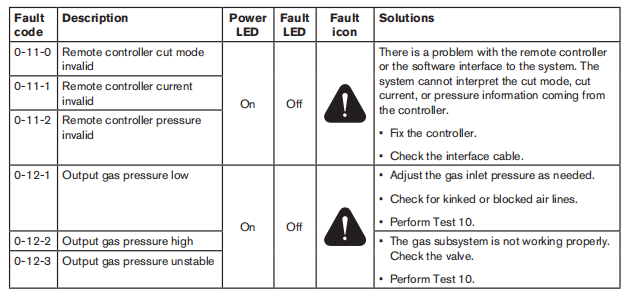
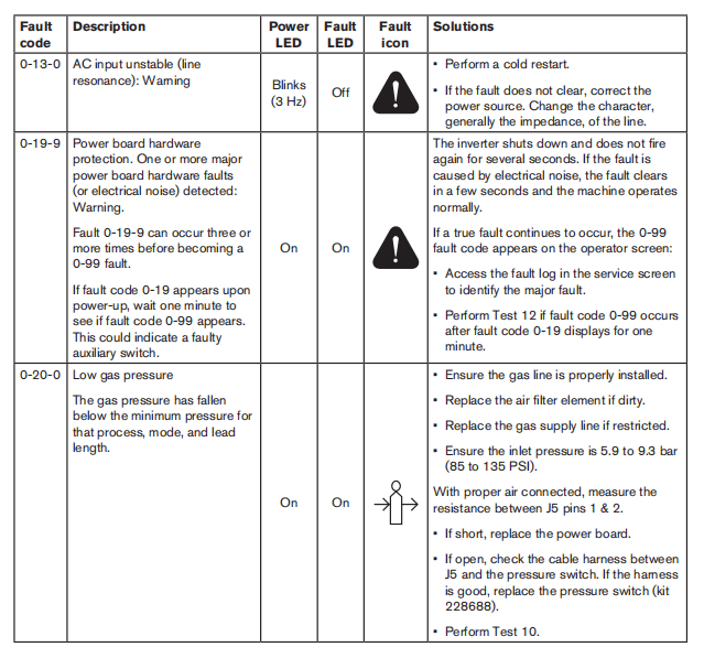
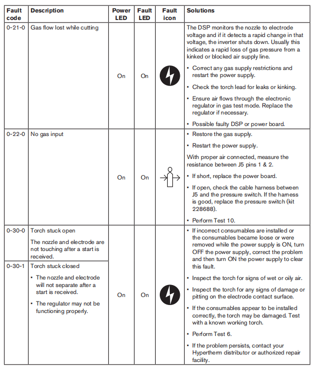
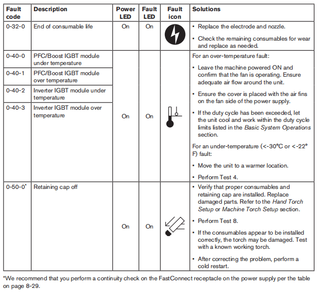
Torch-related faults- Check for continuity between the following points:
| Torch FastConnect receptacle | J17 on the power board |
| 5 | 1 |
| 7 | 2 |
| 6 | 3 |
| 8 | 4 |
| 9 | 5 |
| 10 | 6 |
| 11 | 7 |
| 12 | 8 |
Note: If there is no continuity between any two test points, replace the torch FastConnect receptacle.
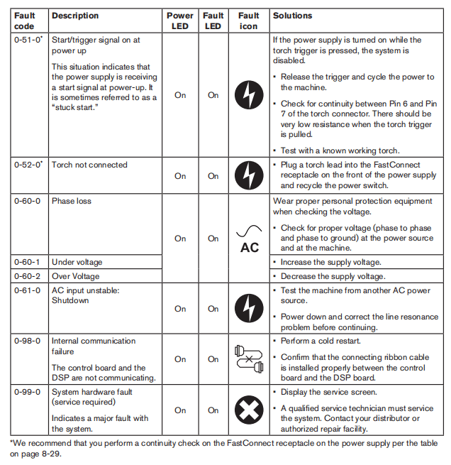
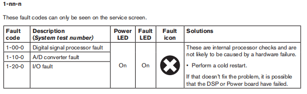
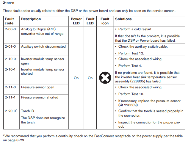
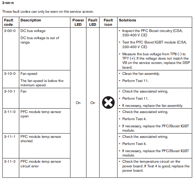
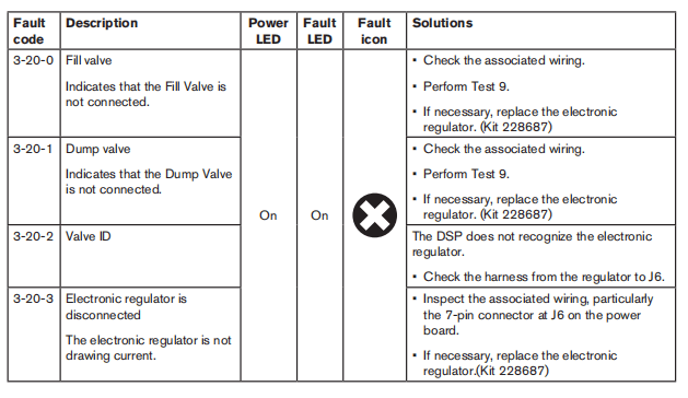
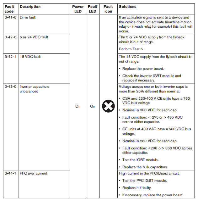
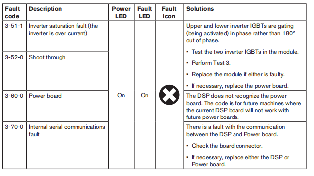
Troubleshooting guide
Note: Fault icons and corresponding fault codes appear in the user display for many errors. lf a fault code appears, refer to page 8-23. Fault codes before using this troubleshooting guide.The following table provides an overview of the most common problems that can arise when using the Powermax and explains how to solve them Soe page 8-42 System tests for detailed test procedures.
| Problem | Meaning | Causes | Solution |
| The ON/OFF power switch is set to ON (I), but the power ON LED is not iluminated. | There is insufficient voltage to the control circuits or a short-circuited power component. | No voltage improper voltage appled to the unit, a faulty power switch (S1), or a faulty input diode. | Check to see that the system is plugged into an appropriately-sized circuit and that the circut breaker has not been tripped. Verify that the power is ON at the main power panel or atthe line-disconnect switch box. Verify that the line voltage is not too low (more than 159% below the rated voltage). Perform Test T to check the incoming voltage and the power switch. Perform Test 12on CSA units. |
| Faulty power board, fan, or solenoid valve. | Perform Test 5 to check the flyback circuit. | ||
| Faulty power board or IGBT. | Perform Tests 1,2,and 3 and replace any faulty components. | ||
| Faulty control board. | Replace the control board. | ||
| Faulty DSP board. | Replace the DSP board |
| Problem | Meaning | Causes | Solution |
| Machine doos not cut well(does not appear to be cutting at full cutting power) and the arc does not time out after 5 seconds. | Inadequate ground. | Poor work lead connection | Verify that the worklead is attached to the workpiece and the workpiece is free of rust, paint, or other coatings. |
| Damaged work lead. | Check the resistance across the work lead. If the resistance is greater than 3Ω, repair or replace the work lead. | ||
| Fauly pilot arc IGBT. | Turn the power OFF, remove the consumables, and check the resistance between the plunger and the work piece. If the resistance is less than 5 kQ, check the resistance across the pilot arc IGBT (two screws on O8). f the nesistance is less than 5kQ, repace the pilot arc IGBT. | ||
| Faulty DSP board. | Replace the DSP board | ||
| Low output from the power supply. | Current is set to low. | Increase the current as needed. |
System tests
| Test# | Description | Associated fault codes |
| 1 | Voltage input | 0-60-ALL |
| 2 | DCpower buss | 3-43-0 |
| 3 | Output diode bridge | General |
| 4 | Temperature out of range | 0-40-ALL2-10-ALL,3-11-ALL |
| 5 | Flyback (DCto DC)circuit | 3-00-0,3-42-ALL3-43-ALL |
| 6 | Torch stuck open/closed | 0-30-ALL |
| 7 | Start signal | General,0-51-0 |
| 8 | Torch cap-sensor switch | 0-50-0 |
| 9 | Electronic regulator | 0-21-0,3-20-ALL |
| 10 | Pressure sensor | 0-12-0,0-20-0.2-11-ALL |
| 11 | Fan | 3-10-ALL |
| 12 | Power switch auxiliary | Unreported interlock at START |
Before performing any tests do the Internal inspection and the Resistance check in Tst 2 below. These tests should only be performed by a qualified service technician. Wear the proper personal protective equipment and use approved tools and measurement equipment.Before purchasing a major replacement component, verify the problem with Hypertherm Technical Service (1-800-643- 9878) or the nearest Hypertherm repair facility.Several connectors require you to remove a white cap to access the test points. The figure below shows examples of connectors located at the top of the power board. You can pry off most covers with your thumbnail. However, you may need to use a small blade screwdriver to carefully pry off some of the covers. Bo carefu not to bend or break the connectors.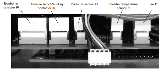
Test 1-Voltage input
Symptom Voltage fault (0-60-0,-1or-2)• Check the line voltage at the top ofthe power switch (S1) with the switch in the OFF position.• Check the input votage to the input diode bridgo with the switch in the ONposition.• The AC voltage between any 2 input wires should equal the ine voltage.• If there is proper voltage to the power switch and low votage to the input diode bridge, replace the power switch.• Check the output voltage of the input diode bridge. – Output VDC = Line Votagex1.414VDC.
Note:All values are± 15%.
| Three phase | |
| L1 | Black (CSA) Brown(CE) |
| L2 | White (CSA) Black (CE) |
| L3 | Red (CSA) Gray(CE) |
| PE | Green (CSA) Ground (GRD) |
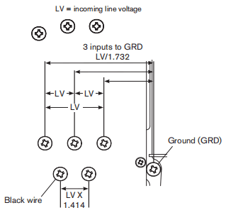
If there is a fault and the diode bridge output value is correct: Display the service screen and confirm that the value “VL”is ± 15% of AC line voltage.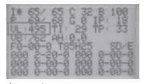
If there is a fault and the “VL” value is correct: – Verify the DSP board by replacing it with a known good board. – If DSP board is not the problem, replace the power board and the PFC IGBT module (CSA and 230-400V CE units only).
Test 2-DC Power Buss
Resistance check
Note: All resistance values must be taken with the power cord disconnected and all internal power supply wires attached. • Remove the mounting screws from the bulk capacitors and pull the caps away from the power board.• Measure resistances described in the following tables.
| 200-600VCSA | |
| Test points | Value |
| TP 7 and 9 | 25 kΩ |
| TP8 and 9 | 25 kΩ |
| 230-400VCE, 380VCCC/230-400VCE | |
| Test points | Value |
| TP 7 and 9 | 25 kΩ |
| TP8 and 9 | 25 kΩ |
| 380VCCC,400VCE | |
| Test points | Value |
| TP 7 and 9 | 25 kΩ |
| TP8 and 9 | 25 kΩ |
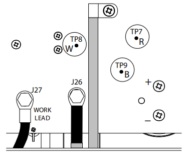
Replace the bulk capacitor mounting screws before power-up.
Voltage check
All voltages must be measured with the input power connected and the machine on.
Note: Wear proper personal protective equipment (PPE) before testing powered equipment, All values are ± 15%.
Check the inverter IGBT module voltages as described below.The voltage measured across the bulk capacitors (half the buss voltage or the smaller values above) should be the same before and during torch operation.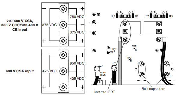
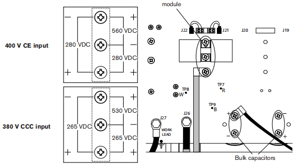
Test 3- Output diodes
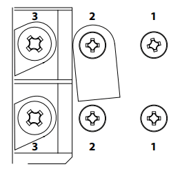
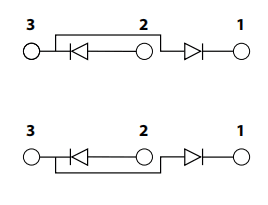
• Tum OFF the powor switch and disconnectthe powor cord.• Check the four diodes in the bidge with an ohmmeter in diode test mode.• For each diode, the value should be “open” (very high resistance) with the meter leads in one direction and 0.1V to1.0Vwith the meter leads reversed. – A diode is shorted if the value is less than 0.1V. Replace both bridges. – A diode is open if the valuo is greater than 1.ovin both dinections. Replace both bridges. Note:In each case, common (black)should be on3.
Test 4-Inverter and PFC temperature sensor
Symptom: Fault code 0-40 appears in the operator screen. Remove power and allow the system to reach room temperature (at last 60 minutes after use).If the system has a temperature interock either fault code 0-40 or faut code 0-99 appears on tho operator screen.Display the service screon and check the “F” field for the live (most recent) fault code. Fault code 0-40 appears on the operator screen, but you need to identify the specific 0-40 fault code variation:0-40-0 PFC module under temperature.0-40-1 PFC module over temperature.0-40-2 Inverter module under temperature.0-40-3 Inverter module over temperature.
If fault code 0-99 appears on the operator screen, display the service screen and check the “F’ fold for:
2-10-0 Inverter module temperature sensor open.2-10-1 Inverter module temperature sensor shorted3-11-0 PFC module temperature sensor open.3-11-1 PFC modlue temperature sensor shorted.
For operational fault codes 0-40-0and0-40-1or power board faults 3-11-0and3-11-1(CSA,230-400VcE,
380 V CCC/230-400 CEmodels only)
1. Remove PFC temperature sensor connector U19) from power board.2. Check the resistance between pins1and 2 onthe plug. Resistance should be about5ko3. If the resistance is incorrect, replace the PFC IGBT module and gate drive cables.4. If the value is correct measure resistance between pins 1 and 2 on J19 on the power board with the temperature sensor disconnected. The resistance should be about 47kΩ.5. If the value is correct, replace DSP board.6.If the value is incorrect, replaco power board.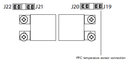
For operational fault codes o-40-2and0-40-3 or power board faults 2-10-0and2-10-1
1.Remove the inverter temperature sensor connector from the top-roar of the power board02).2.Measure the resistance between pins 1 and 3 on the plug3.If the resistance is not within ±15% of 10 kQ replace the temperature sensor.4.If the value is correct, remove the DSP board and measure the resistance between pins 1 and 3 on the power board with the temperature sensor disconnected. The resistance should be approximately 57.6kQ5. If the value is correct, replace the DSP board.6. If the value is incorrect,replace the power board.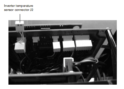
Test5- Flyback circuit (DC minor voltages)
Symptom: Minor voltages are not present. Note: Wear proper personal protective equipment (PPE) before testing powered equipment.The flyback citcuit is the source of the minor DC voltages in the power supply. It provides +3.3VDC,+5VDC,+24 VDC, and +48VDC Check the voltages as described in the table. fa value is not within 土15% perform the appropriate test later in this section.
| Volts DC | Test points (use chassis for negative) |
| 0-60-ALL | All units |
| +48 | J1一Pin1 |
| +24 | J5-Pin1 |
| +5.0 | J3-Pin3 |
| +3.3 | J15-Pin4 |
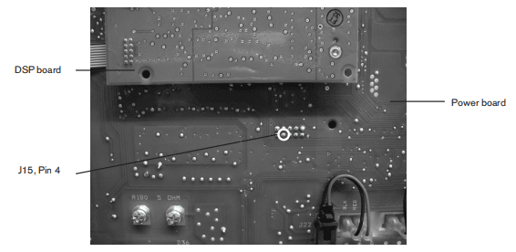
lf the +48VDC value is incorrect:• Romove the fan connector (U1) and repeat the test.• If the value is now corect, replace the fan.• If the value is still incorrect, replace the power board.If the +24VDC value is incorrect:• Remove the pressure switch connector U5)and repeat the test.• If the value is now correct replace the pressure switch.• If the value is stil incorrect, replace the pressure switch connector, remove the solenoid valve connector (6) and repeat the test. If the value is now correct, replace the solenoid valve. If the value is still incorrect replace the power board.If the +5VDC value is incorrect:• Remove the pressure sensor connector O3) and repeat the test.• If the value is now correct, replace the pressure sensor.• If the value is still incorect remove the DSP board and repeat tho test.• If the value is now correct, replace the DSP board• If the value is still incorect, replace the power board.If the +33 VDC value is incorrect:• Remove the DSP board.• If the value is still incorect replace the power board.
Test 6-Torch stuck open (TSo)/torch stuck closed (TSC)
Symptom: No fault occurs at power-up but an 0-30 fault displays on the operator screen when attempting to fire the torch. Confim that all of the proper consumables are installed in the torch.In an idle (no start signal) working system with the torch and consumables installed there should be continuity between the dual black wires connected to the center post of the pilot arc lGBT and the red wire connecting to J28. With gas flowing through the torch (gas test mode 1)ther should be very high resistance between those two points.Note: To set the system to gas test mode, display the serice screen(refer to page 8-23 Displaying the service screen) move the cursor to ‘G” (gas), and use the adjustment knob to toggle to”I” gas test mode). If air does not flow,the regulator might be faulty. Examine the fault log to see if any3-20-n faults are logged.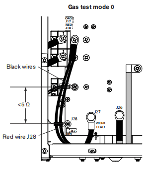
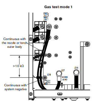
Before continuing, turn OFF the power.If the resistance value is always less than 100 Q, remove the torch and recheck the resistance. If the value is still less than 100Ω.If the resistance is aways greater than 100Ω:• Replace all consumables and recheck.• If the resistance is correct (<100Ω) the old consumables are bad.• If the resistance is still greater than 100Ω, measure the resistance in the torch between the pilot arc wires (Pin 1or 2) and negative an power (the center connection).• If the resistance is still too high, replace the torch and lead.Note:The retaining cap should be snug but not over-tightened.All values are ±15%Check the function of the pilot arc IGBT:• Turn the machine off and disconnect power.• Install a jumper wire (at least 8 AWG) from the work lead (J27)to the plot arciGBT (dual black wires).• Reconnect power and tum on the machine.• Attempt to fire the torch.• If the torch fires, replace the pilot arc IGBT.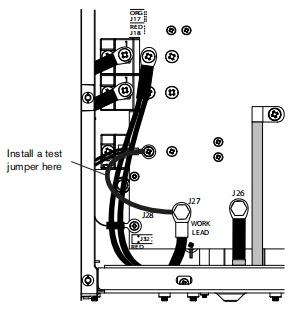
Test 7- Start signal
Symptom: There is no anc when the torch trigger is closed If the start icon is displayed and there is afault code O-51 at power up: • Remove the torch from the systom. • Check the resistance between Pin 6 and Pin 7In the lead plug, with the torch trigger open (not pulled). • If there is very low resistance, inspect the lead set and trigger switch for shorts and replace or repair as necessary.If the icon is not displyed at power up and does not appear when the torch trigger is closed: • Remove the torch from the system. • Close the trigger switch and check the nesistance between Pin 6 and Pin 7. • If there is very high resistance, inspect the lead and trigger switch for opens and replace or repair as necessary.If the icon is not displyed at power up and does not appear when the torch trigger is closed: • Remove the torch from the system. • Close the trigger switch and check the resistance between Pin 6 and Pin 7. • If there is very high resistance, inspect the lead and trigger switch for opens and replace or repair as necessary.If there is no problem found with the torch wiring or trigger switch and there is still no arc or start icon: • Turn the machine off and disconnect power • Remove the nozzle and electrode from the torch and re-install the retaining cap. • Reconnect power and turn the machine on. • Temporarily connect J17 Pin 2to Pin 3.(CATION: Gas will flow to the torch)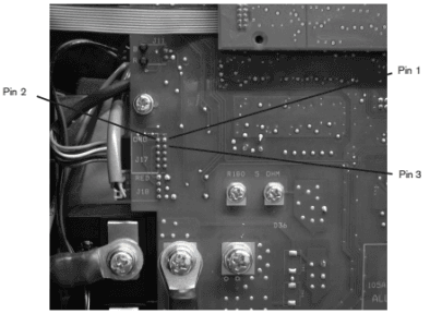
If gas does not flow and there is no start icon on the display, perform the continuity check on page8-29: • Verify the DSP board is working by replacing it with a known good DSP board. • If the DSP board is not the problem, replace the power board.
Test 8-Torch cap switch
Symptom: Fault code 0-50 and the cap-sensor switch icon appear on the operator screen. 1. Confim that the retaining cap is in place. 2.Remove the torch from the power supply and check the resistance between Pin S and Pin 7 in the torch lead plug.a. If the resistance is very high, check for opens in the torch leads and cap sensor switch. b. If the resistance is approximately 0Ω:– Reconnect the torch. – Measure for continuity between Pin 1and Pin 2 at J17 on the power board. – If there is no continuity, inspect and perform a resistance test on the torch disconnect.c. If there is no problem with the leads or switch, test the circuit boards.– Turn off the machine and disconnect power. – Put a jumper wire between J20 pins 1 and 2 – Reconnect power and turn on the machine. – If the cap-sensor switch icon is not displayed, verify the DSP board by replacing it with a known working board. If the DSP is not the problem replace the power board.
Test 9 – Electronic regulator
Symptom: Airflows continuously through the torch. 1. Turn off the machine and disconnect power. 2.Disconnect the electronic regulator control cable (6) from the power board.• If air continues to flow, replace the electronic regulator. • If the air stops flowing, verify the DSP board by replacing it with a known good one. If the DSP board is not theproblem, replace the power board.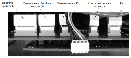
Test 10-Pressure sensor
Symptom: The pressure sensor reading doesn’t agree with known pressures. Note: Wear proper personal protective equipment (PPE) before testing powered equipment.1.Remove the white cover on the plug at J3 on the power board. 2.Turn the machine ON. 3. Measure power to the sensor between Pin 2 and Pn3.If not 5.0(士5%) perform the Flyback Circuit test above. 4. From the service screen enable the gas testNote the flowing gas pressuro in the P’field to the nightof tho sash. 5. Measure VDC between Pin2(-)and Pin1(+)The value should be 0.0463 times the pressure, for example(68PS1″.0463VDC/PSl=3.148VDC). If the voltage measurement is within ±10% of the correct value and you have a pressure warning or fault:a Test with aknown working DSP board. b. If the measured voltage is correct, replace the DSP board. c. If the measured voltage is not correct, replace the pressure sensor.
Test 11-Fan
Symptom: The fan does not operate properly. Note: Wear proper PPE protection before testing powered equipment.1. Remove the inverter temperature sensor plug from J2 on the power board. 2.Place ajumper between Pn Tand Pn 3 of connector J2 on the power board. 3.Remove the white cover from the fan control cable atJ1. 4.Turn the machine ON. (The fan should be running) 5. With the fan control cable connected to J1, measure the DC volage between Pin 1 and Pin4 in the pug.
Test 12-AUXswitch
Symptom: Upon power-up, fault code 0-19 displays. After 1 minute,fault code 0-99 displays. In service mode, the live fault code is 2-01-1.1.Turn the machine off and disconnoct the power2.Disconnect the auxiary switch cable from J5 on the power board3. Measure the nesistance on the cable plug between Pn4and Pin5.4. If the power switch is closed (ON) there shoud be very low resistance.5. If the power switch is open (OFF) there should be very high resistance.6. If the resistance measurement doesn’t agree, check the cable, plug, and switch for opens or shorts.
Section 9 Power Supply Component Replacement
Disconnect the power and gas supply
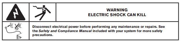
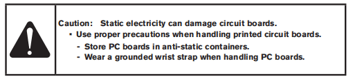
1. Turn the plasma power supply switch to OFF(O).2. Turn the line disconnect switch to OFF(O).3. Disconnect the gas supply hose from the plasma power supply.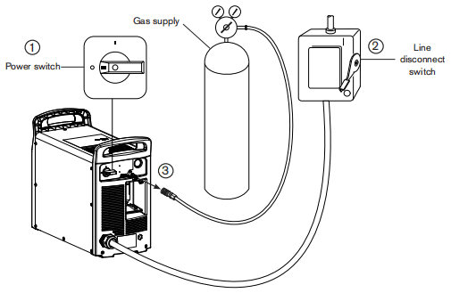
Replace the air filter element
1. Remove the consumables kit that ships beside the fiter bowl on the rear panel.2. Grasp the fiter bowl with your right hand.3. Push down the thumb latch and rotate the fiter bowl approximately 45 degrees to the right.4. Pull the fiter bowl straight down to remove. You can see the white filter element and retaining nut.5. Unscrew (countercockwise) the plastic retaining nut that secures the filter element.6. Roplace the drty clement with a new element Reinstall (clockwise)the plastic retaining nut to finger-tight only.7. Clean the filter bowl.8. Inspect the o-ring at the top of the fiter bowl if necessary, replace theo-ring with the one provided in the kit.Apply a thin film of silicone lubricant to the o-ring before installing.9. Insert the fiter bowl with the thumb latch positioned approximately 45 degrees to the right of center. This is the same orientation in which the filter bowl was pulled down and removed.10. Vertically align the filter bowl. (with metal guard and firmly push the fiter bowd uptothe top of the receptacle to seat the bow. It is helpful to it the bow with your left index finger under the nut on the bottom of the bow.11.Once the bowl is seated properly, rotate the bow 45 degrees to the left until you hear the thumb latch click into place.
Replace the work lead connector
1. Using a razor bade or sharp knife, slice the rubber boot from one end to the other, being careful not to cut into the work lead cable. 2. Remove the rubber boot from the work lead connector.
3. Loosen the work lead connector set screw and pull the work lead cable out of the connector. 4. Slide the new rubber boot over the work lead cable.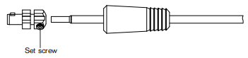
5. Insert the end of the work lead cable into the new work lead connector.6. Tighten the setscrew to 1152kg cm(100in-bs)7. Align the tabs in the rubber boot:with the mating slots in the work lead connector.8. Slide the rubber boot over the work lead connector until it is fully seated.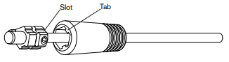
Install the optional fiter kit
1. Remove the gas inlet fitting from the bracket.
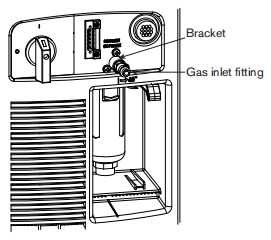
2.Apply thread sealantto the adapterfitting and tighten it into the bracket.Note: Never use Teflon tape on gas fittings. Useliquid pipe sealant.3. Thread the new fter onto the adapterftting. using thread sealant, with the arow pointing toward the power supply.4. Tighten the gas inlet fting into the filter using thread sealant.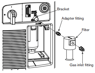
5. Remove the upper two T20TORXscrewSfrom each side of the power supply.6. Place the fiter cover over the fiter on the rearof the power supply, aligning the screw holeswith the holes in the power supply cover.7. Install the four T20 TORX screws providedin the kit, through the fiter cover and powersupply cover. Tighten the screws to 23 kg cm(20in.-bs).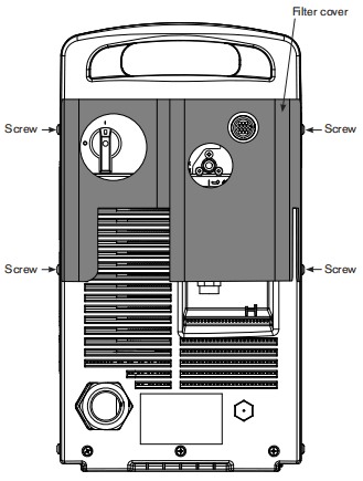
Remove the power supply cover
1.Remowe the16T20TORX screws from the sides and top of the power supply cover. 2. Lift the cover of the power supply.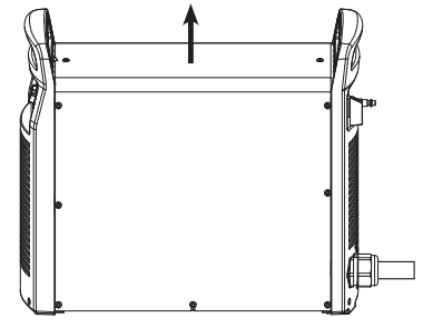
Remove the Mylar barrier
1. Remove the Myar barrier from the power board side of the power supply. The Mylar barier is flexible and can be bent slighly for removal.
Remove the end panel bracket
1.Remove the two mounting screws from the end panel bracket. The screws are located under each end of the end panel bracket. 2. Lift the end panel bracket straight up from the power supply.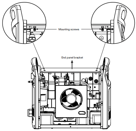
Install the machine interface cable with voltage divider board
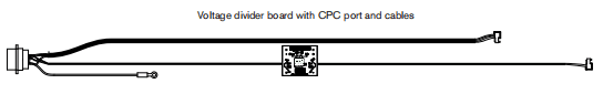
1. Secure the voltage divider board to the right of the power supply fan by tightening two of the supplied screws to 11.5 kg cm (10 in-lbs)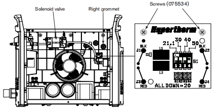
2. Remove the round plastic plug that covers the CPC opening in the rear panel.
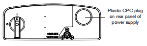
3. Route the CPC port and attached cables above the solenoid valve and over to the CPC port opening on the rear panel of the power supply.4. Insert the CPC port into the CPC port opening from inside the power supply. Be sure to position the port with the green/yellow ground wire at the bottom of the port.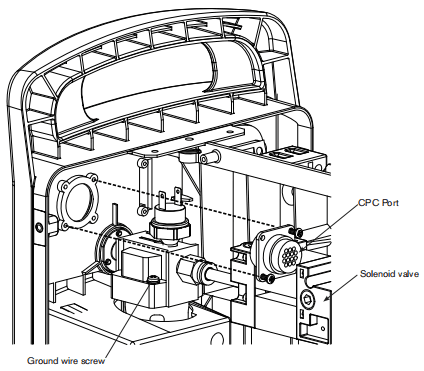
5.Secure the CPC port by tightening two of the supplied screws to 115 kg cm(10n-bs). Two screws are sufficient when inserted in opposite comers of the CPC port.6. Secure the green/yellow ground wire from the CPC port to the gas after housing, using the same screw that secures the large ground wire fom the center panel. Tighten the ground wire screw to 123 kg om(15in-ibs).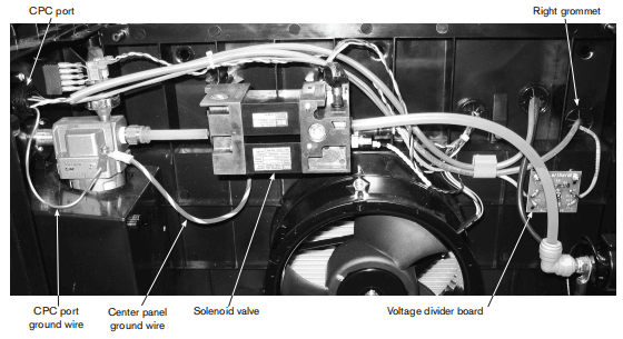
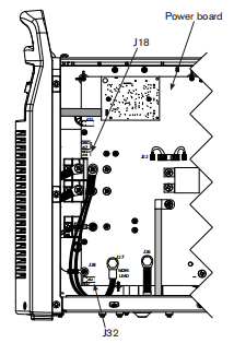
ZRoute the large cable from the CPC pont through the night grommet and down the left side of the power board to theJ18 connector.8. Push the cable connector onto the power board connector. Be sure to align the red wire in the cable connector with “RED” that is printed on the power board.9. Route the small cable (from the right side of the woltage divider toad) through the right grommet and down the lat side of the power board to the J32 connector.10. Push the cable connector onto the power board connector. Be sure to align the red wie in the ablo comectorwith ‘RED’that is printed on the power board.
Set the voltage divider board
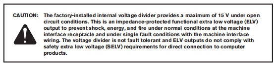
The factory presets the voltage divider to 50:1. To change the voltage divider to a difterent setting:
1. Locate the voltage divider DIPswtches on the leftside of the power supply. The figure below shows the default setting (50:1) with the number 4 switch up.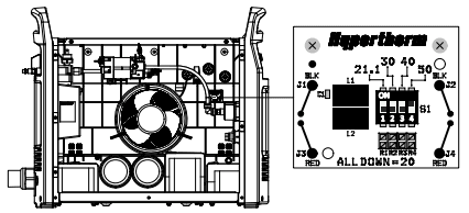
2.Set the DIP switches to one of the following settings.
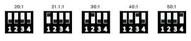
Connect the machine interface cable
1.Remove the machine interace receptacle’s cover from the rear of the powersupply. Note:The cover on the machine interface receptacle prevent dust and moisture from damaging the receptacle when not in use. This cover (part number 127204) should be replaced if damaged or lost.2 Connect the machine interface cable CPC to the power supply.
3. Terminate the machine interace cable spade terminals inside the electrical enclosure of listed and certified torch height controllers or CNC controller to prevent unauthorized access to the connections after instalation. Verify that the connections are correct and that all live parts are enclosed and protected before operating the equipment.
Note:The integration of Hypertherm equipment and customer-supplied equipment including interconnecting cords and cables, if not listed and certified as a system, is subject to inspection by local authorities at the final installation site.
See the Mechanized Cutting” section for more infomation on each type of signal available through the machine interface cable.
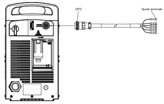
Install the RS485 serial interface cable
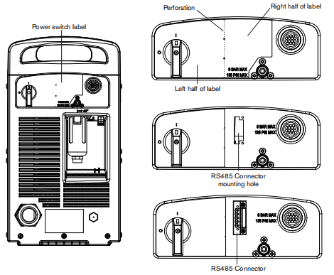
1. Pry up the ight edge of the power switch label using a knife or blade screwdriver.2. Peel the right half of the label back to the perforation.3. Apply pressure to the left half of the label while tearing the right half away. Discard the right half of the label.4.Route the long cable, small connector first, through the RS485 mounting hole in the rear end panel.5. Fasten the RS4B5 connector in the mounting hole of the rear panel, with the red wire on top, by tightening the two supplied #4 pan head screws to 11.5kg cm(10in-bs).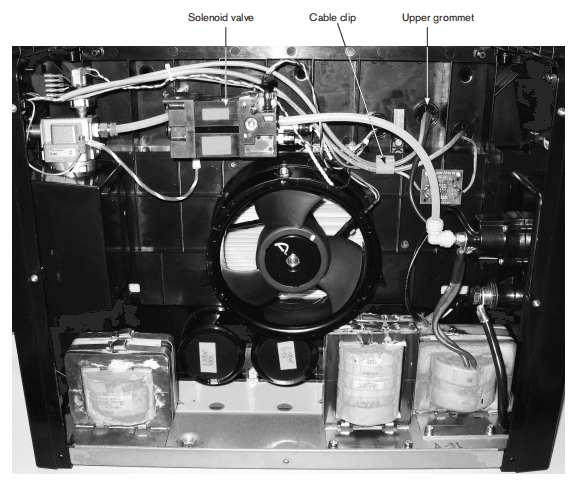
6. Route the long RS485 cable, along with the two existing gray cables, above the solenoid valve and through the cable clip. 7. Push the small connector,from the long RS485 cable, through the upper grommet in the center panel.8.Attach the ground wire (green with yellow stripe) ring connector to the threaded post located between the upper and left grommet.Tighten the supplied nut to the threaded post to 128 kg cm (15 in-lbs). 9.Firmly push the ground wire connector through the upper grommet.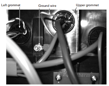
10. Secure the RS485 board to the plastic mounting posts, located on the center panel directly behind the DSP board, by tightening the two supplied #6 pan head screws to 11.5 kg cm (10in-bs) Refer to the figure on the next page. 11. Attach the ground wire connector to the bottom left connector on the RS485 board.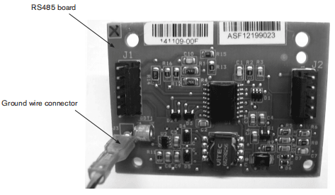
12. Push the connector, from the long RS485 cable, onto the J1 connector ofthe RS4B5 board. 13. Install the short RS485 cable by pushing the connector, with the smaller white dust cover, onto the J7 connector of the DSP board. Push the other connector ontothe J2 connector of the RS485 board.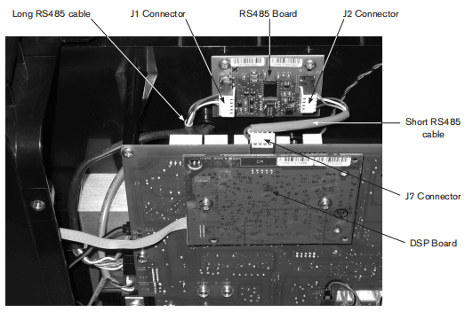
Disconnect the gas tube
1.Push in the plastic ring on the push-to-connecting 2. Gently pull the top of the rear end panel away from the power supply until the gas tube pulls out of the push-to-connect fiting.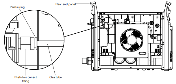
Connect the gas tube
1.Align the end of tha gas tube with the push-to-connect fiting 2. Gently push the top of the rear end panel toward the power supply until the gas tube is fully seated in the push-to-connect fiting.
Remove the power cord
1.Remove the three mounting screws from the bottom of the rear end panel.
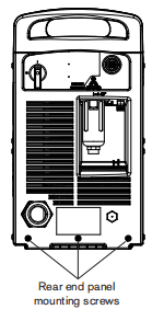
2.Remove the screw securing the ground wire to the heat sink.
Note: CE mode is have a ferite core installed over the ground wire. CSA and CCC models do not have a ferite core on the ground wire.
The power board is removed to show the ground wire connection on the heat sink.
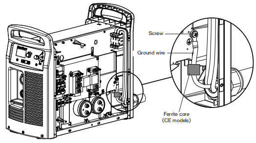
3.Slide the rear end pane approximately 4.0cm (15 inches) away from the power supply. 4. Verify that power to the system has been turned OFF and loosen the set screws that secure the three power wires (L1,L2,L3)to the top of the power switch.5. Pull the wires straight up to remove them from tho power switch. 6. On the outside of the power supply, unscrew the power cord’s strain relief retention nutso that the wires move freely. Slide the nut back along the power cord.7. Pull the wires through the strain relief to remove the power cord. Note: CE power cords must be pulled forward through the strain relief, from inside the rear end panel, because of the forrite core installed on the three power wires.
Remove the strain relief connector
- Loosen and remove the strain relief nut on the inside of power supply.
- Remove the remaining parts of the strain relief connector from the power supply.
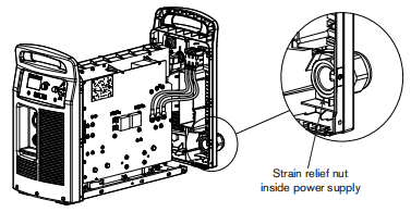
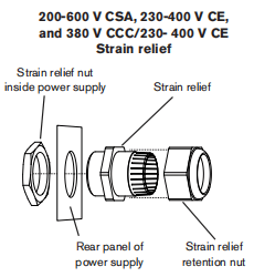
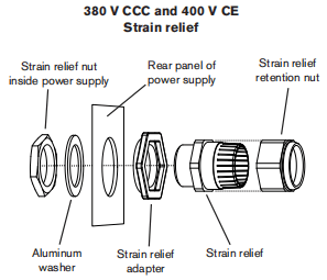
Replace the power switch
1.Remove the three mounting screws from the bottom of the near end panel.2. Slide the rear end panel approximately 4.0 cm (15 inches) away from the power supply.3. Verify that power to the system has been turned OFF and loosen the set screws that secure the three power wires (L1-L2-L3) to the top of the power switch.4. Pull the wires straight up to remove them from the power switch.5. Loosen the set screws that secure the two wines (red, black) to the auxiliary switch located on top of the power switch behind theL1-2-L3 wires.6. Pull the wires straight up to remove them from the auxliary switch.7. Loosen the set screws that secure the three power wires (T1-T2-T3) to the bottom of the power switch.8.Pull the wires straight down to remove them from the power switch.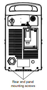
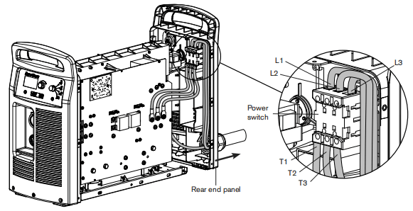
9. Remove the handle screw that secures the power switch handle to the post.10. Pull the power switch handle straight off the post and set aside the handle and screw.11. Pry up the edge of the power switch label using a knife or blade screwdriver.If the optional RS485 connector is not installed, the label extends to the right side of the inlet gas fiting.12. Peel off the entire label to expose the four mounting screws that secure the power switch to the rear end panel.13. Disengage the power switch from the rear end panel by removing the four mounting screws.14. Secure the new power switch to the rear end panel by tightening the four supplied mounting screws to 173kg cm (15in.-lbs).15.If the RS485 connector is installed,bend and tear the now label at the pertoration.16. Peel the backing off the label and afx to the rear end panel, being careful to align tho hole in the label with the corresponding hole in the rear end panel.17. Push the new power switch handle straight onto the post and tighten the handle screw to 115 kg cm(10in-bs)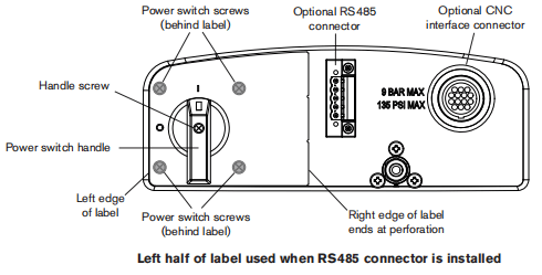
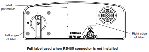
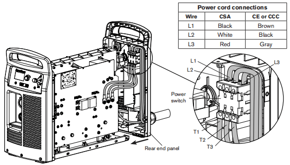
18. Inset the red and black wires in the top of the auilary switch and tighten the set screws to 11.5kg cm(10inHbs). The red wire connects to the “13” teminal and the black wine connects to the “14”terminal19. Insert the three power wires in the bottom of the power switch, in the same order as they were removed, and tighten the T1-T2-T3 set screws to 23kg cm(20in.-bs).20. Insert the three power wires in the top of the power switch, inthe same order as they were removed, and tighten theL1-2-L3 set screws to 23kg cm(20in.-Hbs).21. Slide the rear end panel against the power supply chassis.22. Tighten the three mounting screwsin the bottom of the rear end panel to 23 kg cm (20 in-bs).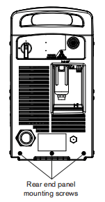
Replace the control board
1. Remove the current adjustment knob and operating mode switch knob from the front panel by pulling them straight off their respective posts.2.Carefully pull the top of the front end panel away from the power supply. The front panel is still attached to the bottom of the power supply and can only move a short distance.3. Remove the three screws that secure the control board to the front panel. Two screws are installed at the top of the control board one attach end. The third screw (not shown) is installed in the middle of the control boad along the bottom edge.4. Carefully slide the control board from behind the front end panel toward the power board side of the power supply.5.Disconnect the ribbon cable from the control board and set aside the control board.6.Plug the ribbon cable into the J6 connector on the new control board.7. Carefully pull the top of the front end panel away from the power supply and slide the control board into place.8. Secure the control board to the front end panel by tightening the three supplied mounting screws to 8.1kg cm (7in.-ibs).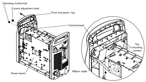
Remove the DSP board
1.Disconnect the DSP connector(1)from the top of the DSP board (3).
Note:This step is only required on systems that have an RS485 communication board installed. Systems without an RS485 communication board installed wil not have a connector plugged into the top of the DSP board.
2Remove the two screws (2) from the DSP board.
Two rows of connector pins (4) ane located on the back of the DSP board (3) as shown in.the figures below.The dashed rectangle identifies the location of the pins on the back of the board.3. Carefully pul the DSP board (3) straightout from the power board (5). Do not bend the pins.4.Disconnect the ribbon cable from the ribbon cable connector (6) onthe back of the DSP board Set the DSP board aside.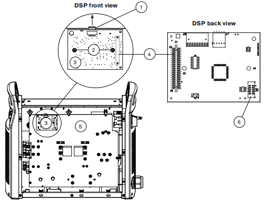
Remove the power board
Complete the instructions below while referring to the applicable figure:
• 200-600VCSApower board on page 9-42 • 230-400VCE,380VCCC/230-400VCE power board on page 9-43 • 380vccC/400V CE power board on page 9-441. Unplug the five wire connectors located at the J1,J2,13,15,and J6 headers on the back side of the power board.2. Disconnect the gate drive wire connectors from the power board.3. Disconnect the PFC temperature sensor connector (all modes except 380v ccc and 400 VCE) from the power board.4. Remove the two 3uF capacitors from the power board.5. Remove all the screws and bolts securing wires to the power board.6. Remove all the remaining screws from the power board except the four board mounting screws and the two transformer mounting screws.7. Remove the four board mounting screws. Do not remove the two transformer mounting screws8. Pull the right-hand edge of the power board forward while pushing the gate drive wires and PFC temperature sensor wires through the openings in the board.Note: Silksceen printing above the openings in the board denotes the color and order of the gate drive wires.The printing is “BLK” (black),”RED” (red),”BLK”(back). “RED” (red) from left to right.9. Unplug the J11and J17 wire connectors from the leftside of the power boand.10. If a CNC interface receptacle is installed on the rear of the power supply, unplug theJ1B andJ32 wire connectors from the left sido of the power board.11.Remove the power board from the power supply and set aside.
200-600V CSA Power Board
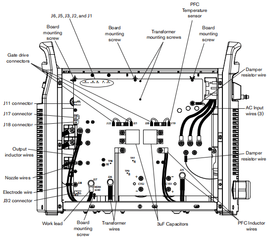
230-400V CE, 380V CCC/230-400V CE Power Board
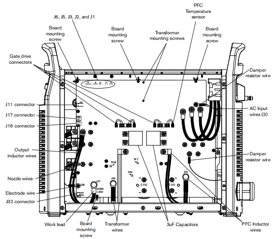
380V CCC-400V CE Power Board
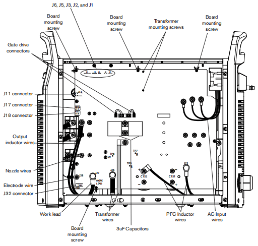
Replace the input diode bridge
Complete the instructions below while refering to the applicable figure:
• 200-600V CSAheat sink compononts on page 9-50 • 230-400vcE,380vcCC/230-400V CE heat sink components on page 9-51 • 380VCCC/400VCE heat sink components on page 9-521. Remove the two mounting screws from the input diode bridge.2. Remove the input diode bridge from the heat sink3. Clean the area where the input diode bridge was mounted,using isopropyl alcohol to remove the old themal grease from the heat sink.4. Apply a thin coat(3 mils, approximately the thidkness of asheet of paper) of themal grease evenly to the input diode bridge mounting surface.5. Orient the input diode bridge correctly and mount it to the heat sink by gently tightening the two supplied screws.6. Altemately step torque the two mounting scrows to tho proper torque value as shown in the applicable figure.
Replace the output diode bridge
Complete the instructions below while refering to the applicable figure:
• 200-600VCSAheat sink components onpage 9-50 • 230-400 vcE,380vcCC/230-400VCE heat sink components on page 9-51 • 380vcCC/400 V CE heat sink compononts on page 9-521.Remove the four mounting screws from the output diode bidge.2. Remove the output diode bnidge from the heat sink.3. Clean the area where the output diode bridge was mounted, using isopropyl alcohol to remove the old thermal grease tom the heat sink.4. Apply a thin coat (3mils, approximately the thickness of a sheet of paper) of thermal grease evenly to the output diode bridge mounding surface.5. Orient the output diode bridge correctly and mount it to the heat sink by gently tightening the four supplied screws.6. Altemately step torque the four inpunting screws to the proper torque value as shown in the applicable figure.
Replace the pilot arc IGBT
Complete the instructions below while referring to the applicable figure:
• 200-600VCSA heat sink components on page 9-50 • 230-400VCE380VCCC/230-400VCE heat sink components on page 9-51 • 380vCCC/400V CE heat sink components on page.9-521.Remove the two mouning screws from the plot an IGBT.2. Remove the pilat arc lGBT from the heat sink.3. Clean the area where the pilot arc IGBT was mounted using isopropyl alcohol to remove the add thermal grease from the heat sink.4. Apply a thin coat (3mils approximately the thickness of a sheet of paper) of themal grease evenly tothe pilot arc IGBT mounting surface.5. Orient the plot arc IGBT correctly and mount it to the heat sink by genty tightening the two supplied screws.6. Aternately step torque the two mounting screws to the proper torque value as shown in the applicable figure.7. Connect the supplied cable to the pilot arc IGBT terminals. The black wire connects to the top teminal (labelled E2″or “7) and the red wire connects to the bottom terminal (labelled ‘G2’or”6”).
Replace the inverter IGBT module
Complete the instructions below while refering to the applicable figure:
• 200-600VCSAheatsink components on page 9-50 • 230-400vcE,380VCCC/230-400V CE heat sink components on page 9-51 • 380vCCC/400VCE heat sink components on page 9-521.Remove the four mounting sorows from the inverter IGBT module.2. Remove the thermal sensor and set it aside.3. Remove the inverter IGBT module from the heat sink.4. Clean the area where the inverteriGBT modue was mounted,using isopropyl alcohol to remove the old thermal grease from the heat sink.5. Apply a thin coat(3 mls, approximately the thickness of a sheet of paper)of themal grease evenly to the inverter IGBT module mounting surface.6. Orient the inverter IGBT modue correctly and mount it to the heat sink by gently tightening the four supplied screws, using the ionger screw to capturethe ring teminal of thethemal sensor between the screw head and the upper left mounting hole of the inverter IGBT module.7. Altemately step torque the four mounting screws to the proper torque value as shown in the applicable figure.8. Connect the supplied cables to the inverter IGBT module terminals. Attach the black wire from one cable to the”6″ terminal and the red wire to the “7 terminal. Attach the black wire from the remaining cable to the ‘5’terminal and the red wire to the “4”terminal.
Replace the PFC IGBT module
Complete the instnuctions below whle referring tothe applicable figure:
• 200-600VCSAheat sink components on page9-50 • 230-400vcE,380vcCC/230-400V CEheat sink components onpage 9-511. Remove the four mounting screws from the PFC IGBT module.2. Remove the PFCIGBT module from the heat sink.3. Clean the area where the PFC IGBT module was mounted,using isopropyl alcohol to remove the old thermal grease from the heat sink.4. Applya thin coat (3 mib, approimatey the thickness of asheet of paper) of themal groaso ovonly to the PFC IGBT module mounting surface.5. Orient the PFCIGBT modue corecly and mount itto the heat sink by gonty tightening the four supplied screws.6 Atemately step torque the four mpunting sorews to the proper torque value as shownin the applicable figure.7. Connect the suppled cables to the PFC IGBT module terminals. Attach the black wire from one cable to the’G2 terminal and the red wire to the E2 terminal. Attach the black wire from the remaining cable to the”E1″teminal and the red wire to the’G1″teminal.
Replace the snubber resistor
Complete the instructions below whle referring to the applicable figure:
• 200-600VCSAheat sink components on page 9-50 • 230-400vcE380vCCC/230-400V CE heat sink components on page 9-51 • 380vcCC/400V CEheat sink components on page 9-521. Remove the two mounting screws from the appropriate snubber resistor.2. Remove the snubber resistor from the heat sink.3.Clean the area where the snubber resistor was mounted, using isopropyl alcohol to remove the old thermal grease from the heat sink.4. Apply a thin coat (3 mils, approximately the thickness of a sheet of paper)of thermal grease evenly to the snubber resistor mounting surface.5. Orient the snubber resistor correctly and mount it to the heat sink by gently tightening the two supplied screws.6. Alternately step torque the two mounting screws to the proper torque value as shown in the applicable figure.7. Tighten the two supplied standoffs, in the threaded holes of the snubber resistor,to 11.5kg cm(10in-lbs).
Replace the damper resistor
Complete the instructions below while refeming to the applicable fgure:
• 200-600VCSAheat sink components on page 9-50 • 230-400VCE380vCCC/230-400VCE heat sink components on page9-511.Remove the two mounting scnews from the damper resistor2. Remove the damper resistor from the heat sink.3. Clean the area where the damper resistor was mounted, using isopropyl alcohol to remove the old thermall grease from the heat sink4. Apply a thin coat (3 mds, approimately the thickness of a sheetofpaper) ofthemal grease evenly to the damper resistor mounting surface5. Orient the damper resistor correctly and mountitto the heat sink by gently tightening thetwo suppied screws.6. Aternately step torque the two mounting sorews to the proper tonque value as shownin the applicable figure.
Replace the thermal sensor
Complete the instructions below while referring to the applicable figure:
• 200-600VCSAheat sink components onpage9-50 • 230-400 vcE,380vCCC/230-400VCEhead snk components onpage9-51 • 380vcCC/400VCEheat sink components on page 9-52