
High Power Fiber Laser Series 1KW to 3kW
High Power Fiber Laser
Series YLS-K
Output power 1 to 3kW
Translation of the Original Operating Manual
Installation, Operation and Maintenance
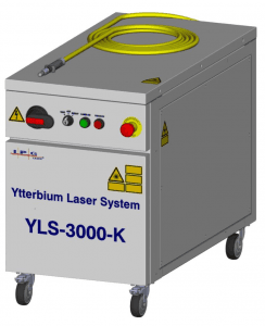
Table of contents
1 General information …………………………………………………………………. 7
1.1 Manufacturer…………………………………………………………………………… 7
1.2 EU Declaration of Conformity ……………………………………………… 7
1.3 Target groups for this operating manual………………………….. 8
1.4 Warranty ………………………………………………………………………………….. 8
1.5 Formal information about the operating manual……………. 9
1.6 Presentation of safety instructions………………………………….. 10
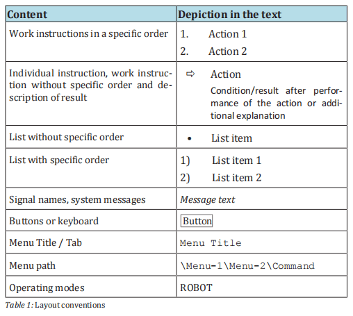
1.7 Layout conventions …………………………………………………………….. 13
1.8 Directory of abbreviations…………………………………………………. 14
1.9 Licensing agreements…………………………………………………………. 15
2 Safety…………………………………………………………………………………………. 18
2.1 Safety instructions ………………………………………………………………. 18
2.2 Intended use …………………………………………………………………………. 18
2.3 Non-intended use ………………………………………………………………… 19
2.4 Obligations of the system owner ……………………………………… 19
2.5 Responsibility of the operating personnel …………………….. 20
2.6 Personnel qualifications…………………………………………………….. 20
2.7 Safety-conscious working………………………………………………….. 21
2.8 Personal protective gear ……………………………………………………. 21
2.9 Specific dangers……………………………………………………………………. 22
2.9.1 Electrical energy……………………………………………………………… 22
2.9.2 Laser radiation ………………………………………………………………… 22
2.9.3 Gas and particle emission……………………………………………… 23
2.9.4 Sound level……………………………………………………………………….. 23
2.10 Safety equipment…………………………………………………………………. 24
2.10.1 E-Stop button …………………………………………………………………… 25
2.10.2 External safety interface ……………………………………………….. 25
2.10.3 Fiber break monitoring …………………………………………………. 26
2.11 Warning labels……………………………………………………………………… 26
2.12 Independent alteration or replacement parts procurement ……………………………………………………………………………………….. 27
3 Device description…………………………………………………………………… 28
3.1 Functional principle ……………………………………………………………. 28
3.2 Overview ……………………………………………………………………………….. 30
3.2.1 Operating elements ………………………………………………………… 31
3.2.2 Interfaces and connections ……………………………………………. 32
3.2.3 Fiber connector………………………………………………………………… 32
3.2.4 Main components…………………………………………………………….. 34
3.2.5 Electrical mounting plate……………………………………………….. 35
4 Delivery and transport ……………………………………………………………. 36
4.1 Scope of delivery…………………………………………………………………… 36
4.2 Delivery and transport………………………………………………………… 36
4.2.1 Unloading…………………………………………………………………………… 37
4.2.2 Unpacking the product……………………………………………………. 38
4.2.3 Transport to the installation site………………………………….. 38
4.3 Returning the product…………………………………………………………. 42
5 Assembly and installation ………………………………………………………. 43
5.1 Space requirements and room conditions………………………. 44
5.2 Supply connections………………………………………………………………. 44
5.2.1 Supply voltage ………………………………………………………………….. 44
5.2.2 Cooling water supply………………………………………………………. 45
5.3 Set up the product………………………………………………………………… 45
5.4 Running lines and fibers……………………………………………………… 45
5.5 Connecting the product ………………………………………………………. 46
5.5.1 Connecting the supply voltage ……………………………………… 47
5.5.2 Connecting the external interfaces………………………………. 50
5.5.3 Connecting the fiber connector to the process optics ……………………………………………………………………………………………… 51
5.5.4 Connecting the water supply ………………………………………… 52
5.6 Installing the software…………………………………………………………. 55
6 Acceptance and commissioning……………………………………………… 56
6.1 Visual inspection…………………………………………………………………… 56
6.2 Work to be performed before commissioning……………….. 56
6.3 Transfer to operation…………………………………………………………… 57
6.4 Recommissioning …………………………………………………………………. 57
7 Operation…………………………………………………………………………………… 58
7.1 Operating modes…………………………………………………………………… 58
7.2 Switching on/off …………………………………………………………………… 59
7.3 Switching on the laser power supply……………………………….. 61
7.4 TEST mode …………………………………………………………………………….. 62
7.4.1 Working without the laser program……………………………. 63
7.4.2 Working with the laser program………………………………….. 64
7.4.3 External control ……………………………………………………………….. 64
7.4.4 Analog control ………………………………………………………………….. 66
7.5 ROBOT mode ………………………………………………………………………… 67
8 LaserNet software……………………………………………………………………. 70
8.1 System requirements………………………………………………………….. 70
8.2 Installing the software………………………………………………………… 70
8.3 Establishing a connection to the laser…………………………….. 74
8.4 Starting LaserNet…………………………………………………………………. 76
8.5 LaserNet user interface………………………………………………………. 77
8.6 LaserNet menu description……………………………………………….. 78
8.6.1 File menu ………………………………………………………………………….. 80
8.6.2 Configuration menu ……………………………………………………….. 81
8.6.3 View menu………………………………………………………………………… 90
8.6.4 Extras menu……………………………………………………………………… 91
8.6.5 Help menu ………………………………………………………………………… 93
8.7 LaserNet status indicators…………………………………………………. 93
8.8 LaserNet tabs………………………………………………………………………… 93
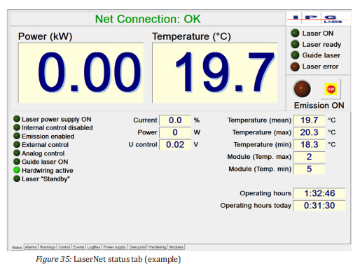
8.8.1 Status tab ………………………………………………………………………….. 93
8.8.2 Alarms tab ………………………………………………………………………… 95
8.8.3 Warnings tab……………………………………………………………………. 96
8.8.4 Control tab………………………………………………………………………… 97
8.8.5 Events tab …………………………………………………………………………. 99
8.8.6 Logfiles tab…………………………………………………………………….. 100
8.8.7 Power supply tab………………………………………………………….. 101
8.8.8 Chiller tab ………………………………………………………………………. 102
8.8.9 Dew point tab………………………………………………………………… 104
8.8.10 Hardwiring tab ……………………………………………………………… 105
8.8.11 Modules tab……………………………………………………………………. 105
8.9 LaserNet program editor ………………………………………………… 106
8.9.1 LaserNet program editor editing window………………. 107
8.9.2 Command list for laser programs……………………………… 108
8.9.3 Laser program editor command descriptions……….. 110
9 Maintenance ………………………………………………………………………….. 112
9.1 Maintenance work ……………………………………………………………. 113
9.1.1 Clean fiber connectors ………………………………………………… 113
9.1.2 Measuring the laser output power …………………………… 121
9.1.3 Measuring the beam quality………………………………………. 122
9.1.4 Checking the water outlet…………………………………………… 123
9.2 Replacement and repair work ……………………………………….. 125
9.2.1 Replacing a laser module……………………………………………. 126
9.2.2 Replacing the feeding fiber ………………………………………… 126
9.3 Maintenance of the water system (IPG chiller)………….. 127
10 Messages and troubleshooting……………………………………………. 128
10.1 Information about message displays……………………………… 128
10.2 Status messages, warnings and alarms………………………….. 128
10.3 Troubleshooting………………………………………………………………….. 128
10.4 Manufacturer’s service………………………………………………………. 129
10.4.1 Behavior in the event of malfunctions ……………………… 129
10.4.2 Downloading the log files via LaserNet ……………………. 131
10.4.3 Downloading the events file via LaserNet……………….. 135
10.4.4 Downloading the configuration overview via LaserNet …………………………………………………………………………………………… 136
10.4.5 Updating the firmware and product configuration.. 138
10.4.6 Resetting critical errors……………………………………………….. 139
11 Decommissioning and disposal …………………………………………… 141
11.1 Temporary decommissioning………………………………………….. 141
11.2 Permanent decommissioning…………………………………………… 142
11.3 Disposal…………………………………………………………………………………. 143
12 Appendix…………………………………………………………………………………. 144
12.1 Status messages, warnings and alarms………………………….. 144
12.1.1 Messages of the Status tab…………………………………………… 145
12.1.2 Messages of the Alarms tab…………………………………………. 148
12.1.3 Messages of the Warnings tab ……………………………………. 157
12.1.4 Messages of the Control tab………………………………………… 161
12.2 Technical data……………………………………………………………………… 162
12.2.1 Scale drawings……………………………………………………………….. 162
12.2.2 Rating plate of the laser……………………………………………….. 164
12.2.3 Dew point temperatures……………………………………………… 164
12.3 EU Declaration of Conformity ………………………………………….. 166
1 General information
This operating manual enables safe and efficient operation of the prod- uct “high power fiber laser” (hereafter referred to as the product).
This operating manual is an integral part of the product and contains allimportant information about the assembly, startup, operation andmaintenance of the product.
The operating and maintenance personnel must have carefully read andunderstood this operating manual before beginning any work.
The safety instructions in this operating manual must be followed. Fail-ure to follow the safety instructions can lead to personal injuries, damage to the device or environmental damage.
This operating manual must be kept in the product’s immediate vicinity and accessible to the operating personnel at all times.
1.1 Manufacturer
Registered office
in Germany
IPG Laser GmbH
Carl-Benz-Straße 28
57299 Burbach
1.2 EU Declaration of Conformity
The Declaration of Conformity of the product can be found in the appendix to this operating manual.
1.3 Target groups for this operating manual
The translation of the original operating manual for the product was created by IPG Laser GmbH for the operating and maintenance personnel of the system owner.
The operating personnel must have corresponding vocational training and be trained in the operation of the product (see Personnel qualifications [20]).
The maintenance personnel are responsible for the assembly/installation, maintenance and repair.
The personnel must have been trained inmaintenance of the product by IPG Laser GmbH or another competent IPG branch office.
Successful participation in the training is confirmed with a certificate (see Personnel qualifications [20]).
1.4 Warranty
IPG Laser GmbH offers a warranty for all of its products with regard to material and manufacturing defects for the period specified in the applicable purchase contract or in the specifications. The warranty period begins on the date of delivery agreed upon in the purchase contract.
In addition, IPG Laser GmbH guarantees that this product satisfies all applicable specifications in normal operation.
During the warranty period, IPG Laser GmbH may choose to repair orreplace a product that is found to be defective in the opinion of IPG Laser GmbH with regard to material and manufacturing defects.
Warranty period
The warranty period for all products repaired or replaced during the
warranty period is limited to the remaining period of the original warranty period and is only offered for the individual defective product.
IPG Laser GmbH reserves the right to issue a credit for all defective
products that have proven to be faulty during normal operation.
Contact qualified IPG personnel for all maintenance work. All inquiries in connection with repairs or replacements within the
framework of this warranty must be made immediately after the
defect was discovered; such inquiries must be made directly to
IPG Laser GmbH or its local representative.
Driver software
Current and future software is subject to the non-exclusive licensing
conditions of IPG Laser GmbH. Using the software automatically constitutes acceptance of the licensing conditions.
Service and repairs
When sending back components / products, observe the following instructions:
• Never send the product back to IPG Laser GmbH without enclosing a valid RMA number (Return Material Authorization). The
RMA number can be obtained from the Service department of IPG
Laser GmbH.
• The costs for repair of the product will be invoiced to the customer if the product or repair is not covered under the warranty.
• Articles that are sent back to IPG Laser GmbH upon request must
be shipped in a suitable container / packaging.
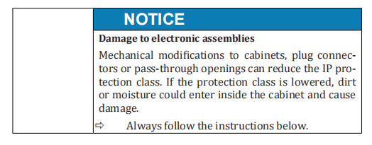
Protection class
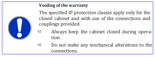
The IP protection classes specified in the specifications apply to theelectrical and electronic components of the product.
Mechanical changes can lead to a lower protection class, thereby voiding the warranty.
Reservation of
the right to make
amendments
IPG Laser GmbH reserves the right to make changes to the design or
construction of its products at any time without any obligation to imple-
ment or install these changes in units purchased at an earlier point in
time.
1.5 Formal information about the operating manual
IPG Laser GmbH grants no usage rights, either directly or indirectly, under a patent or other industrial property rights or copyright on the basis of the use of information provided in this document.
Copyright 2018 IPG Laser GmbH. All rights reserved. It is prohibited to reproduce this publication, share it with third parties store it in retrieval systems or adapt it in any way what so ever without the express written authorization of IPG Laser GmbH.
IPG Laser GmbH believes that the information provided is correct and reliable.
IPG Laser GmbH provides no warranty of any kind, except withregard to the information in this document, including the assurance of suitability for general or specific use.
Furthermore, IPG Laser GmbH accepts no responsibility for the use of information in this document, for patent violations or rights of third parties that result from the use of this information.
Trademarks
Designations that serve as trademarks retain their legal status with or
without labeling as trademarks.
Service
In the event of errors that cannot be rectified using this operating manual, please contact the competent IPG service department.
Accompanying
documents
In addition to this operating manual, the complete documentation in-
cludes the following:
• Commissioning report
• Circuit diagram
• Layout of the installation panel
• Accessories list
• Technical data
• Declaration of Conformity
Additional system documents in accordance with contractual agreements.
1.6 Presentation of safety instructions
Warnings
• protect against possible injuries and property damage.
• indicate the magnitude of the danger by means of the signal
word.
• indicate the risk of personal injury with the danger symbol.
• describe the type and source of the danger.
• state the risk and possible consequences.
• present measures for avoiding dangers and prohibit specific actions.
General warning
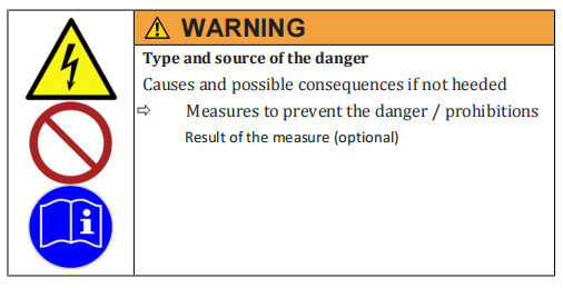
Safety symbols
Safety symbols are displayed in the left column of the warning:
- The safety label designates warnings that warn against personal injury.
- Theprohibition sign indicates an action that may not be performed.
- Themandatory sign indicates a required action that must be performed to prevent danger.
Signal word
The selected signal word indicates the magnitude of a potential dangerand the probability of its occurrence.
Source of the danger
The type and cause of the danger are specified here.
Possible consequences of failure to heed the warning
The possible consequences of failure to heed the warning are, for exam-ple, crushing injuries, burns or other severe injuries.
Additional explanations can also be given here.
Measures / prohibitions
Actions that must be taken to avoid a danger or that are prohibited in order to avoid a danger are listed under measures / prohibitions.
The result information is provided if the danger no longer exists after the warning or prohibitions are heeded or the danger potential has changed.
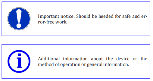
Signal words


Additional instructions
1.7 Layout conventions
Various symbols and numbering styles are used in this operating manual in order to designate work instructions, lists, status descriptions,etc.
The most important layout conventions are listed below.
1.8 Directory of abbreviations

1.9 Licensing agreements
Software licensing agreements for LaserNet
IPG Laser GmbH®
Single user license
SOFTWARE LICENSING AGREEMENT
Read the conditions of this software licensing agreement carefullybefore using the software. IPG Photonics and/or its subsidiary IPGLaser GmbH (hereafter “IPG”) grants you as the end user a usage license only under the condition that you accept all conditions of this licensing agreement.
A legal contract enforceable by law is hereby established between you and IPG Photonics. Through a written declaration of acceptance, you accept the conditions of this agreement.
License
The software licensed by this agreement (collectively “Software”) is the
property of IPG and is protected by copyright. Once you have accepted
this licensing agreement, you receive certain usage rights for the soft-
ware. This license regulates all versions, revisions or improvements to
the software that IPG may make available to you. Except as modified by
an IPG license document, a license certificate or a license key that pre-
cedes, follows or is enclosed with this license, your rights and obliga-
tions with respect to the use of this software are as follows:
You may:
• Use the software on a single computer (Windows operating system).
• Create one copy of the software for archiving purposes or copy
the software to the hard drive of your computer and keep the
original for archiving purposes.
You may not:
• Issue a sublicense for any portion of the software, lease or lend
out the software; furthermore, you may not disassemble, decom-
pile, take apart, modify or translate the software or attempt to
decrypt the source code of the software or create works derived
from the software.
• Use previous versions of the software after you have received a
replacement set of CDs or an updated version. After updating of
the software, all copies of the previous versions must be de-
stroyed.
• Use a later version of the software than is granted to you via this
licensing agreement, unless you have purchased permission to
update or otherwise acquired in a separate form the right to use
such a later version.
• Use IPG software on data carriers for which you have no permis-
sion within the scope of a license module.
• Use the software in a way that is not permitted by this license.
Use of the software and updating
IPG provides the software only in connection with a fiber laser of the
company IPG.
Specific IPG software products contain content that is updated from
time to time. You can receive updates to the content for the period for
which you have subscribed to updates to the content (including each
subscription that is included upon purchase of the software), purchased
update rights for the software or concluded a maintenance agreement
that includes updates to the content or for which you have otherwise
purchased the right to receive updates to the content. This license does
not entitle you to receive or use updates to the content in any other
form.
Warranty
IPG offers no warranty that the data carrier on which the software is
sold is free of errors. Your sole remedy in the event of a violation of this
warranty is that IPG, at its own discretion, will replace faulty data carriers that are returned to IPG within the warranty period. IPG offers no
warranty that the software will meet your requirements or that the operation of the software will be without disruptions or that the software
is free of errors.
The above warranty applies exclusively and in the place of all other
warranties, regardless of whether express or implicit, including the implicit warranty with regard to the general suitability for use, suitability
for a specific purpose and in regard to the non-violation of rights to intellectual property.
Exclusion of liability in the event
of damages
IPG accepts no complaint or claim of damage originating from the use of
the software.
IPG is, as permitted in maximum form by the applicable laws and independent of whether a remedy depicted in this document fails in its primary purpose, not liable to you in any case for special consequential, direct or similar damages, including lost profit or loss of data, even if IPG
was informed of the possibility of such damage.
In no case shall the liability of IPG or its licensors exceed the purchase value of the software.
Limited rights
All products and documentation of IPG are commercial in nature. The
software and software documentation are “commercial articles”.
Export
The export or re-export of this software is regulated in each case by the
locally applicable laws and regulations. The export or re-export of the
software to an entity on the list of prohibited trade partners and other
blacklists published by the various public authorities is strictly prohibited.
General information
This agreement and every license module associated with it represents
the entire agreement between you and IPG with regard to the software
and replaces all previous or simultaneously established oral or written
agreements, proposals and representations in regard to this issue; it takes priority over all contradictory and supplemental conditions of every offer, every order, every confirmation or similar agreement between the parties.
This agreement shall be terminated by a violation of the conditions contained herein; in this case, you must cease use of the software and destroy all copies of the software. The exclusion of liability in regard to
warranties and damages as well as the restrictions of liability remains
in effect even after termination of the agreement. This agreement can
only be modified by a license module that is enclosed with this license
and/or by a written document that has been signed by you and IPG. If
you have questions concerning this agreement or would otherwise like
to contact us, please write to IPG.
2 Safety
The product was designed, manufactured and tested for safety accord-ing to the currently applicable safety rules and laws and current engineering practices. The product is in a technically fault-free condition.
However, the product can pose dangers when it is
- operated by personnel without proper training.
- used improperly or contrary to the intended use.
- not in a fault-free condition from a safety perspective.
2.1 Safety instructions
Normal operation
Operation of the product is only permitted if all safety equipment is in
operation.
Secure access to the work zones using isolating protection equipment
with safety interlock function (laser cell) such that the area outside the
work zones satisfies the requirements of laser class 1.
The product housing must always be closed and locked during opera-
tion. Issue the housing key only to authorized personnel for mainte-
nance and repair work.
Maintenance
Maintenance work may only be performed by trained experts.
Never operate the product with faulty or non-operational electrical connections.
Comply with the inspection and maintenance intervals specified by the
manufacturers for electrical and mechanical components.
Always perform cleaning and maintenance work on the product while it
is shut down. Always follow the procedure for decommissioning of the
product described in this operating manual. Immediately following
completion of the work, all safety features and protection equipment
must be reattached or put into operation.
Only permit authorized and appropriately trained personnel who have
received safety training to access the product. Always close the product
housing after maintenance work.
In the event of faults in the energy supply, switch off the product immediately.
2.2 Intended use
The product is intended exclusively for material processing, in particular for cutting and welding applications on metals and metal alloys.
2.3 Non-intended use
The operational safety of the supplied product is only guaranteed if the intended use is complied with. The limit values listed in the technical data must be complied with.
The use of optics (e.g. fiber coupler, process fiber, process optics) that are not authorized by IPG Laser GmbH is not covered by the warranty.
2.4 Obligations of the system owner
The system owner must ensure that the safety and health of the operat-ing personnel are always protected during use of the product.
The system owner must ensure that
- the product is used only as intended (see Intended use [}18]).
- the product is used only in a flawless, properly functional condi- tion.
- all safety and warning signs are affixed to the product and read- able.
- appropriate fire protection is present at the setup location.
- the safety equipment is always freely accessible and is regularly inspected.
- the responsibilities of the assigned personnel are defined and complied with.
- only properly trained or educated personnel operate, maintain or repair the product.
- the operating personnel has completely read and understood the operating manual and knows all the safety instructions and residual dangers described in the operating manual.
- first aid is made possible for the operating personnel (e.g. through first aid training and appropriate first aid equipment).
- the personal protective gear is available to the operating and maintenance personnel and used in accordance with the applicable regulations.
- the operating personnel are not under the influence of drugs, alcohol or medications that reduce reaction speed.
- the safety- and risk-conscious work of the personnel is regularly inspected.
- any specified maintenance and inspection work is performed on time.
- electrical work is only performed by qualified electricians.
- in addition to the instructions in this operating manual, the rules and regulations for accident prevention as well as the environmental and occupational safety regulations of public authorities and industry associations applicable at the usage site are complied with.
- the operating manual is available for consultation at the installation location of the product at all times and is in a readable condition.
2.5 Responsibility of the operating personnel
Every operator of the product
- must be trained in and follow the fundamental rules with regard to safety-conscious work, accident prevention and the operation of the product.
- must know the currently applicable statutory provisions on laser safety.
2.6 Personnel qualifications
The areas of responsibility, competency and supervision of the personnel must be precisely regulated by the system owner.
The personnel assigned to assemble, maintain, operate and inspect theproduct must have the corresponding qualifications for performing this work.
Any lack of knowledge on the part of the personnel must be corrected through training and instruction.
Operating personnel
The operating personnel was trained and instructed in the operation of
the product.
If the product is operated in conjunction with an industrial robot, corresponding training is necessary for the operation of the robot (generally
by the manufacturer of the robot).
The operating personnel may only:
• Operate the product.
• Carry out cleaning work (except for cleaning of the fiber connector).
Maintenance personnel
The maintenance personnel consists of experts who have the corresponding qualifications for performing the work listed below.
The maintenance personnel must have been trained in maintenance of the product by IPG Laser GmbH or another competent IPG branch office,unless this work is performed by employees of IPG Laser GmbH.
After corresponding training by IPG, the maintenance personnel may
perform the following work:
Assembly and installation
- Set up or assemble the product
- Run lines and fibers to the product
- Connectthe product (the voltage supply must be connected by an electrician)
- Install the software
Maintenance
- Preventive maintenance work to maintain operational readiness
- Independenttroubleshooting according to the information on troubleshooting in the section on status messages, warnings and alarms
All other work may only be performed by employees of the competent IPG service department itself or by appropriately qualified personnel after consultation with this service department.
Specially qualified specialist
personnel
Specially qualified specialist personnel are people who have been
trained, assigned and instructed by the owner of the end product in
which the described product has been incorporated. These people are
familiar with the pertinent standards, provisions, accident prevention
regulations and operating conditions on the basis of their education, experience and training. They are authorized to perform the respectively
necessary activities and to recognize and avoid any dangers that may
arise in this process. Qualified personnel may
• replace electrical and mechanical components (electrician).
2.7 Safety-conscious working
Existing national regulations for accident prevention as well as any internal work, operating and safety regulations of the system owner mustbe complied with.
Any contact protection present for moving parts maynot be removed from products that are in operation. Dangers from electrical energy must be prevented.
The product may only be operated in accordance with the intended useand in a fault-free condition.
2.8 Personal protective gear
The system owner must provide the following personal protective gear.
- Laser safety glasses (900 …1200 nm)
- Safety shoes
- Safety gloves
2.9 Specific dangers
Specific dangers can arise during operation of the product:
- Dangers from electrical energy
- Dangers from laser radiation
- Dangers from gas and particle emissions
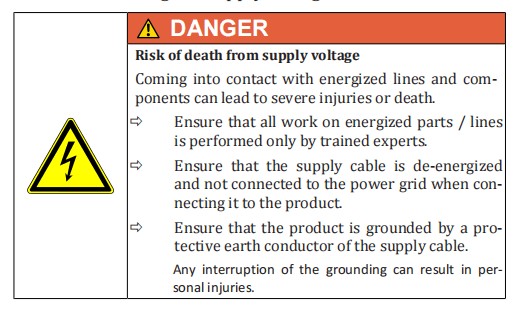
2.9.1 Electrical energy
The product must be connected to a sufficient power supply for operation.
The system owner must ensure that the power supply is in flawless condition.
The isolations and connections of all electrical supply lines must be undamaged.
The protective earth conductor (PE) may not be interrupted at anypoint.
Work on electrical components may only be performed by qualified electricians. For all work on electrical components, the five safety rulesmust be followed:
- Disconnect
- Secure against reconnection
- Verify absence of voltage
- Ground and short-circuit
- Cover or cordon off nearby parts still under voltage.
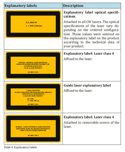
2.9.2 Laser radiation
The product emits energy-intensive radiation with a power level in the kW range and a wavelength of approximately 1068 nm.
The precise specifications of the laser power and wavelength can be found in the supplied technical data.
The danger from laser radiation arises from:
- direct laser radiation
- reflected laser radiation
- scattered laser radiation
Information on important safety measures for working with laser radiation can be found in your regional accident prevention regulations.
These regulations make reference to the harmonized standard EN60825-1, which exists internationally as the standard IEC 60825-1.
Laser classes
Lasers are classified into various classes based on their danger potential. The meaning of the laser classes according to standard Norm EN
60825-1 is described briefly below. A precise definition of the laser
classes with indication of limits of accessible radiation can be found in
this standard.
Class 1
Laser systems that are safe in normal operation even with prolonged direct observation of the laser beam and even if the exposure occurs in
connection with optical instruments (magnifying glasses or telescopes).
Class 2M
Laser systems that emit visible radiation that is safe for the naked eye
only in event of brief exposure. An eye injury can be caused by exposure
through focusing optical instruments (magnifying glasses, telescopes,
microscope, etc.).
Class 4
Laser systems for which direct viewing of the beam and skin exposure
are dangers and for which even the viewing of the diffuse reflections
can be dangerous. These lasers also frequently pose a fire risk.
Classification of
the product into
laser classes
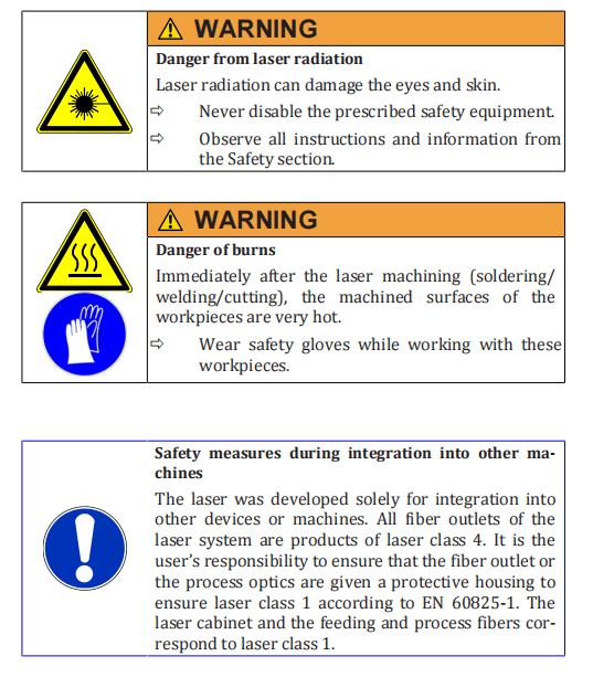
With suitable protective housing and protection covers, the product satisfies the requirements of laser class 1.
With opened protective housing and bypassed safety switches (if
present) as well as directly at the point of beam exit from the process
fiber, the product falls under laser class 4.
The guide laser of the device in the visible spectral range from 600 nm to 700 nm satisfies the requirements of laser class 2M as long as the
cross-section is not reduced by optical instruments (e.g. microscope).
2.9.3 Gas and particle emission
The intended use of the product consists of cutting and welding applica-tions on metals and metal alloys.
During the processing of some materials, toxic gases can be produced by the interactions between the laserbeam and the material during the cutting or welding process. This must be taken into account by the system owner. The product itself does not emit any hazardous substances.
2.9.4 Sound level
The A-weighted noise emissions level LpA for the product is less than 70 dB(A).
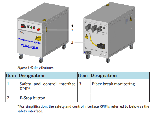
2.10 Safety equipment
The danger zone is secured by safety features. The safety features consist of:
- E-Stop button
- External E-Stop
- Fiber break monitoring
The figure below shows the positions of the safety features on the product.
The status of the individual safety features is indicated in the LaserNet software in the Status tab [} 93] and the Alarms tab [} 95].
The triggering of a safety feature has the following effect:
- The corresponding safety circuit is opened.
- The main power supply is shut down.
- The laser emission is shut down.
Switching on the
main power supply
In order to switch on the main power supply, all safety circuits must be
closed and the safety control of the product must be reset.
Close all safety circuits.
If all safety circuits are closed, the safety control of the product can be reset manually.
The following options are available to you for performing a manual re- set (Switching on the laser power supply [} 61]):
- Laser ON illuminated pushbutton
- Ethernet interface for the LaserNet software
- Safety interface
- Hardwiring interface (optional)
Another option consists of the bus system (see corresponding supplied protocols).
ð Use one of the options to reset the safety control and switch on the main power supply.
The green light of the Start illuminated pushbutton on the front side of the product lights up as soon as the safety control of the product has been reset and the main power supply has been switched on.
Monitoring the
status
The status of the product can be monitored via the safety interface.
When the laser power supply is switched on, the contacts are closed.
They can be used, among other uses, to control external warning lamps.
The signal for the status of the E-Stop button is connected to the safety
interface (status of E-Stop button, 2-channel safety output) and can be
integrated into the safety circuit of the system owner.
2.10.1 E-Stop button
An E-Stop button is located on the front side of the product. Pressing ofthe E-Stop button leads to an immediate shutoff of the laser power sup-ply and thereby the laser emission. After triggering of the E-Stop button,laser emission is no longer possible.
To switch the laser power supply back on, the E-Stop button must be re-set.
2.10.2 External safety interface
- 2-channelsafety signal external E-Stop. If this input is not active, no laser emission can be enabled.
– Safety characteristics according to EN 13849-1, PL d, category 3.
– A safe emergency stop shutdown of the laser emission and can be achieved with a secure two channel signal removal at this interface.
The system integrator can use this data for a safety subsys- tem within its overall safety chain (sensor systems – logic – actuator system).
The contact assignments are described in detail in the enclosed technical data.
2.10.3 Fiber break monitoring
The feeding fiber and the process fiber of the product are continuously monitored (electrical contact).
In the event of a fault, the laser emission is switched off.
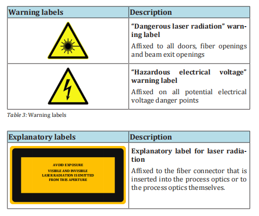
2.11 Warning labels
The explanatory and warning labels affixed to the product are shown in the following overview.
2.12 Independent alteration or replacementparts procurement
Alteration or modifications to the product are only permitted with the written approval of the manufacturer.
Original spare parts and accessories authorized by the manufacturer serve to ensure safety. Failure toheed these instructions results in exclusion of all liability.
3 Device description
The series of high power fiber laser described in this operating manualwas developed particularly for welding and cutting applications on metals and metal alloys.
Depending on the configuration, the type and number of connections and operating elements as well as the power of the laser can vary.
The precise information can be found in the supplied technical data.
3.1 Functional principle
The laser radiation is generated in these laser modules, which are integrated in the laser. Every laser module can be understood as an independent laser.
The output power of the laser modules can differ depending on the type. The number of modules is determined by the nominal outputpower of the laser.
The laser modules require direct voltage to generate the laser radiation.
The direct voltage is generated by the laser power supply, which is integrated into the laser.
The radiation generated in the laser modules is guided by the associated fibers into the combiner module, where they are combined into asingle fiber.
The fiber from the combiner module is spliced to the feeding fiber in the splice box; the laser radiation is fed here into the feedingfiber.
Via the feeding fiber, the laser radiation enters the external welding optics, which are specific to the system owner and focus the laser radiation on the material processing point.
Depending on the selected configuration, the feeding fibers may differ in core diameter and length.

3.2 Overview

3.2.1 Operating elements
The operating elements of the high power fiber laser are described below.
The number and arrangement of the operating elements can vary based on the configuration of the laser.
For more information about your product, see the supplied technical data.

3.2.2 Interfaces and connections
The number and arrangement of the interfaces and connections canvary based on the configuration of the product.
The complete overview of existing interfaces of your product, as well as the interface description and the contact assignment of the customer interfaces, can be found in the supplied specifications.

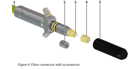
3.2.3 Fiber connector
All lasers are supplied with a feeding or process fiber with a fiber connector located at the end.
The quartz block at the end of the fiber connector is used as an optical output of the laser and is protected against knocks and shocks by a protective conduit or protective glass (depending on the ordered configuration).
The protective glass offers protection against contamination of the quartz block and can be exchanged quickly if necessary.

Depending on the ordered configuration and laser power, different fiber
connector types are delivered that are designed for optics and laser out-
puts. The fiber connector types differ in their diameters and shape of
the mounting surfaces, core diameters of connected fibers and the way
they are assembled in the optics. The existing fiber connector types are
shown in the following figure. The exact dimensions of the respective
fiber connectors can be found in the appendix.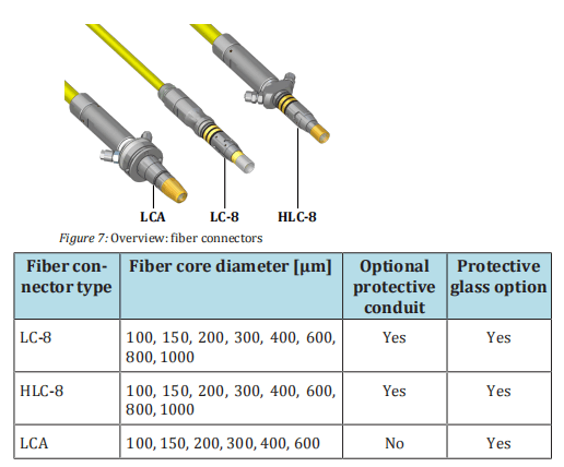
For recommendations on the process-dependent use of the protective
conduit or the protective glass, see the section Clean fiber connectors
[} 116].
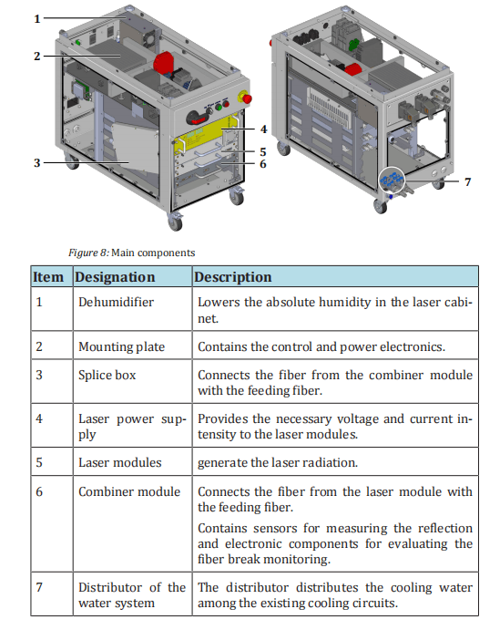
3.2.4 Main components
The main components of the high power fiber laser are described below.
The number and arrangement of the components can vary based on the configuration of the laser.
For more information about your product, see the supplied technical data.
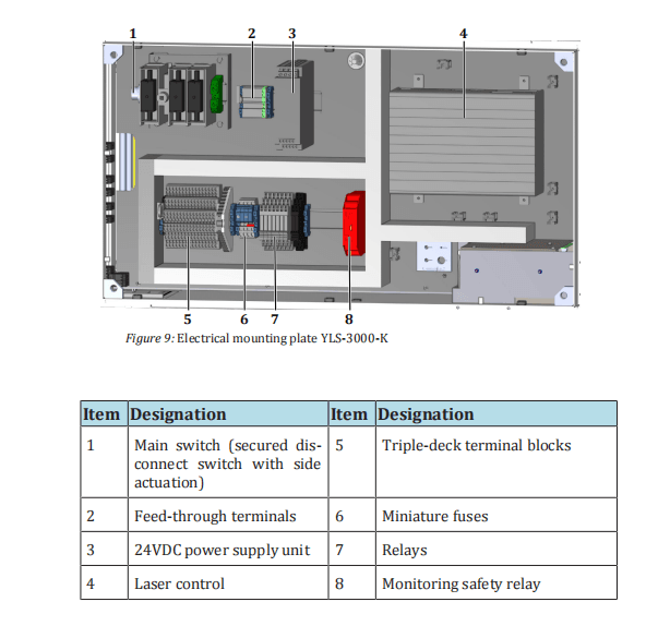
3.2.5 Electrical mounting plate
The electrical mounting plate of the high power fiber laser is shown as an example in the following figure.
The components and their arrangement on the mounting plate can vary based on the configuration of the laser.
The exact layout of the mounting plate of your laser as well as the information about the components used can be found in the supplied circuit and layout diagram of the mounting plate.
4 Delivery and transport

4.1 Scope of delivery
The delivery consists of:
- high power fiber laser
- CDwith the software LaserNet and operating manual for the product
- Accessories (see supplied accessories list)
4.2 Delivery and transport
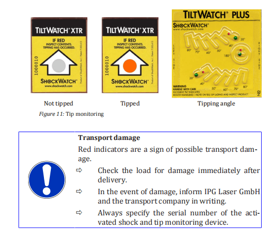
The product is delivered in packaging that offers maximum protection.
The packaging is equipped with a shock and tip monitoring that warns in event of improper handling.
If the packaging shows signs of external damage or the shock and tip monitoring was activated, immediately inform the transport company and your
representative at IPG LaserGmbH.

4.2.1 Unloading
The product is delivered in a wooden transport crate. The product and the accessories are delivered on transport pallets.
The system owner is responsible for the unloading of the components and their transport to the final installation site of the product.
4.2.2 Unpacking the product

Unpacking
ð Remove the product and the supplied accessories from the packaging.
Packaging material
ð Save the packaging material and the inserts in case transport or
storage are required in the future or until any irregularities are
resolved.
Completeness
ð Consult the delivery documents to verify that all parts are
present and complete. If parts are missing or the product is dam-
aged, immediately notify IPG Laser GmbH.
4.2.3 Transport to the installation site
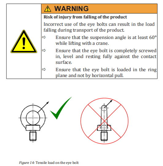
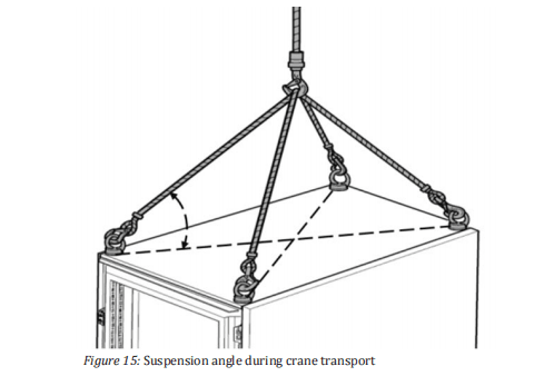
Transport with a
crane
The product is equipped with threaded plates for fastening the eye
bolts. These are located underneath the upper cover.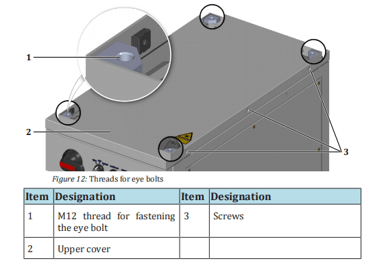
1. Remove the M5 countersunk screws on the left and right side of
the upper laser cabinet cover.
2. Carefully lift the upper cover.
The upper cover is connected to the frame of the laser cabinet by a grounding
wire. The grounding wire is fastened to the grounding connector (star point) with a
flat connector.
3. Disconnect the flat connector of the grounding wire from the
grounding connector on the frame.
4. Remove the upper cover.
- Screw the four eye bolts into the provided threaded plates (M12 thread).
You can now use a suitable lifting device to lift the product out of the transport packaging and bring it to the installation site.
Transport on
casters
Products with robust casters can be moved to their installation site over
short distances without additional aids.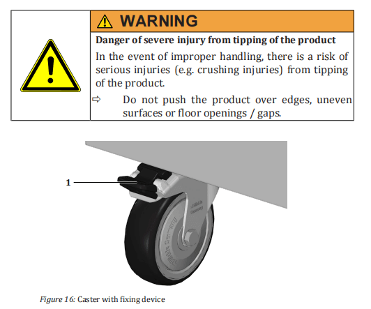
ð Unlock the fixing device on the front casters of the product to be able to move the product.
ð Move the product on its casters only over short distances and on smooth, level floors.
ð Set up the product on a level surface.
ð Secure the product against unwanted rolling by pushing the fixing device on the front casters down.
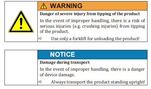
Transport with a
forklift
ð If the product has casters, ensure that the casters are locked using the fixing device to prevent the product from rolling off the
pallet.
ð Ensure that the product is sufficiently secured during transport.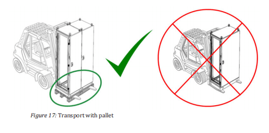
4.3 Returning the product
ð Only return the product when asked to do so by IPG Laser GmbH.
ð Never send a product back to IPG Laser GmbH without enclosing a valid R eturn M aterial A uthorization number (RMA no.).
The RMA number can be obtained from the IPG Laser GmbH service department.
ð Use suitable packaging for the return shipment of the product.
We recommend that you use the original packaging.
ð Secure the product with the available wooden crossbar (1) to prevent transport damage (see the example in the figure below).
5 Assembly and installation

Installation
Observe the following points for installation of the product:
ð Select the installation position such that access to the product
from all sides is guaranteed. A minimum distance of 1 m must be
maintained on all sides.
ð Note the weight of the product as well as the temperature and
humidity limits when selecting the installation site.
ð Make certain that the product is only installed on level, paved
surfaces to ensure the stability of the product.
ð Install the product such that no damage can result from internal
traffic or transports.
5.2 Supply connections
ð Make sure that all supply connections required for operation of the product are available and usable.
5.2.1 Supply voltage
The product requires a voltage supply of 3 x 400 VAC at 50 Hz or 3 x460 VAC at 60 Hz (see the table below).
The connection has four poles(L1, L2, L3, clockwise phase sequence and PE).
Additional information regarding electrical connection values can be found in the supplied specifications.

Electrical connection
The electrical connection takes place in the product (feeding through
screw connection on back side).
5.2.2 Cooling water supply
Tap water
The tap water serves for cooling of the laser modules. The following requirements must be met:
• The water hardness may not exceed 0.25 dH.
• The electrical conductivity should not exceed 50 µS/cm.
5.3 Set up the product
If the product is not located at its final installation site, follow the instructions given in Transport to the installation site [} 38] for setting up the product at its final location.
5.4 Running lines and fibers
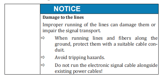

Unpacking fibers
1. Remove the cable ties or tape with which the fiber is fastened to
the product or the transport box.
2. Remove the plastic bag at the end of the fiber.
Running the fiber
3. Take the fiber connector in your hand and roll out the fiber with-
out twisting.
4. Run the fiber in a suitable cable channel.
5.5 Connecting the product
ð Attach all lines to the product such that it is possible to move the
product 1 m in any direction for assembly work.
ð Use only the provided electrical plug connectors.
ð Close all unused interfaces with the provided protective caps.
ð Consult with IPG Laser GmbH before manufacturing deviating
supply lines (in particular interface cables).
ð Do not add any additional openings to the cabinets.
ð Carefully close the cabinet of electrical or electronic components
after installation.
5.5.1 Connecting the supply voltage
Follow the steps below to connect the voltage supply:
- Removethe M5 countersunk screws on the left and right side of the upper laser cabinet cover.
- Carefully lift the upper cover.
The upper cover is connected to the frame of the laser cabinet by a grounding wire. The grounding wire is fastened to the grounding connector (star point) with a flat connector.
- Disconnect the flat connector of the grounding wire from the grounding connector on the frame.
- Remove the upper cover.

- Run the supply cable through the cable gland on the back side of the product.
- Connect the protective earth conductor PE to the green/yellow terminal.
- Check the rotary field (clockwise) of the supply voltage.
- Connect the wires of the supply cable to the terminals L1, L2, L3 of the main switch in accordance with the rotary field.
- Attach the supply cable in the interior of the housing using cable ties to the housing frame.
- Secure the supply cable against strain with the screw fitting.
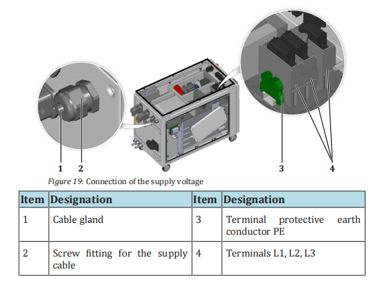
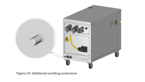
- Reconnectthe grounding line of the upper cover to the grounding connector and screw the upper cover to the laser cabinet.
| Additional earthing | 12. Create an additional earthing of the product at the connection (threaded bolt M8 x 16mm) for the leakage current. The minimum cross section of the earth cable must be 10 mm². |
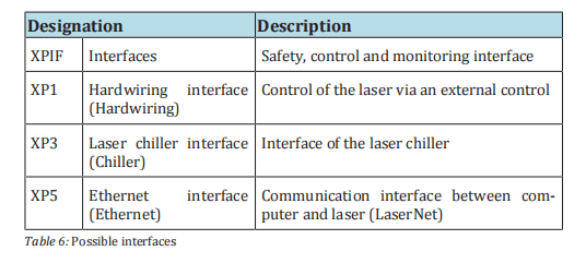
5.5.2 Connecting the external interfaces
The number and arrangement of the interfaces and connections can vary based on the configuration of the product.
The complete overview of existing interfaces of your product, as well as the interface description and the contact assignment of the customer interfaces, can be found in the supplied specifications.
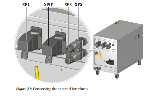
The following table lists all interfaces with which the product can be equipped.
The actual number and arrangement of the interfaces depends on the ordered product configuration.
ð Connect the interface cables according to the supplied technical data. Note the pin assignment.
ð Ensure that the interlocks of the plug connectors snap into place.
5.5.3 Connecting the fiber connector to the processoptics
Before you plug the fiber connector into the welding optics, this must be checked and if necessary cleaned of contamination.

Fiber connectors are generally equipped with a protective glass or aprotective conduit to protect the sensitive quartz block at the fiber end from contamination or damage during installation. Depending on thearea of application and the required laser power, it may be necessary tounscrew the protective glass or protective conduit.

The section Clean fiber connectors [} 113] includes instructions for cleaning the fiber connector, correct use of quartz block protection as well as the correct installation of the fiber connector in the welding optics.
Follow the instructions in this chapter to safely connect the fiberwith the welding optics.
5.5.4 Connecting the water supply
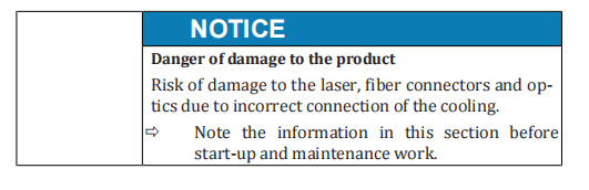

ð Note the following points when connecting the water supply:
- Workon the cooling water distribution may only be performed by IPG service personnel or specially trained experts.
- Aninsufficient supply of cooling water can lead to damage to the laser or the optics.
- Installing bridges or bypasses, etc., is not permitted since the optimal cooling of individual components cannot be guaranteed in this case.
ð When connecting, observe the following values according to the supplied technical data:
- Water flow
- Water pressure
- Water temperature
The product is a model without integrated laser chiller. The laser must be cooled by an external cooling system.
The cooling water is distributed to the laser modules inside the product. The water connections are located on the rear of the product.
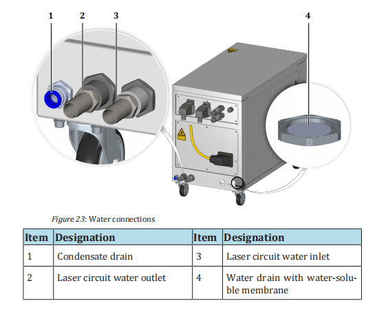
The product is equipped with a water drain with a water-soluble membrane in the cabinet bottom.
In the case of a leakage inside the laser, the membrane dissolves and the water can flow out through the waterdrain.
ð When connecting the water supply, take care that the water drain does not get wet as this could cause the membrane inside to dissolve.
The absence of the membrane impairs the seal of the cabinet so that the correct microclimate inside the cabinet can no longer be guaranteed.
Connecting the
water supply
1. Connect the hoses of the tap water supply to the laser circuit connections according to the designation. Note the direction of water
flow.
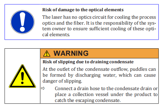
- Ensure sufficient cooling of the process optics and the fiber connector.
The fiber connector is equipped with temperature sensors that trigger an error inthe laser if the upper limit is exceeded (see supplied technical data).
5.6 Installing the software
The software LaserNet is included with the product. LaserNet serves foroperation and monitoring of the laser and its auxiliary components.
Fast Ethernet 100 Mbit/s is used as the interface between the computer and the laser.
The section LaserNet software [} 70] offers information on system requirements as well as software installation.
6 Acceptance and commissioning
The commissioning of the product takes place in cooperation with the service personnel of IPG Laser GmbH.

6.1 Visual inspection
The visual inspection offers an initial overview of the condition of the installation.
ð Ensure the following:
- The space room conditions must be taken into account.
- A space of 1 m must be maintained on all sides of the product.
- The casters of the product must be locked (if present).
- All plug connectors must be locked or screwed onto the product.
- Theproduct cabinet and the fiber must not exhibit any visible damage.
6.2 Work to be performed before commissioning
ð Perform all acceptance tests in the supplied commissioning report.
The product is ready for production operation after successful completion of the acceptance tests.
6.3 Transfer to operation
The responsible service staff member at IPG laser GmbH signs the commissioning report.
The authorized representative(s) of the system owner checks the commissioning report for accuracy and completeness and signs it.
After signing of the commissioning report, the product is transferred to production operations to be commissioned.
6.4 Recommissioning
After a prolonged shutdown, the product must be completely inspected before being commissioned again.
ð Carry out the entire commissioning procedure.
7 Operation
7.1 Operating modes
The product can be operated in two operating modes.
TEST
Operating mode TEST is for manual operation of the laser. In TEST
mode, the laser can be controlled via the LaserNet software and maintenance work can be performed.
ROBOT
The ROBOT mode is the automatic mode of the laser and the standard
operating mode for production operation. The laser is controlled via the
hardwiring interface or an external fieldbus interface, if present. The
LaserNet software is used for monitoring the laser operation.
7.2 Switching on/off
Switching on
1. Ensure that the supply line of the supply voltage is connected.
- Ensure that all protection covers of the product are firmly installed and, if present, all doors of the product are closed.
- Ensure that the water cooling of the product is switched off first.
- Switch on the product with the main switch.
- Turn the key switch on the front side of the product to TEST or ROBOT, depending on the application.

- If necessary, wait for some time until the installed dehumidifier has lowered the dew point temperature to a temperature that is below the temperature of the coldest laser module.
The current dew point measurement can be checked in the LaserNet software in the Dew point tab (see section Dew point tab [} 104]).
The temperature of the coldest laser module can be read from the Status tab (see section Messages ofthe Status tab [} 145]).
- Ensure that the supply lines for water are connected to the product.
- Switch on the external laser chiller.
Switching off

After completing the work (production operation), switch off the laser according to the following procedure:
- Turn the key switch on the front side of the laser to OFF.
- Switch off the laser with the main switch.
- Switch off the external laser chiller.
7.3 Switching on the laser power supply
Various options for switching on the laser power supply are described below.
Safety interface
The safety interface is located on the back side of the laser. Closing of
the potential-free contacts at this safety interfaces switches on the laser
power supply (see External control [} 64]). To switch the laser power
supply back on again, such as after a fault, the contacts must first be
opened (for the pin assignment of the safety interface, see the supplied
technical data).
LaserNet software
In TEST mode (manual operation), the laser power supply can be
switched on via the LaserNet software.
Hardwiring interface
In ROBOT mode, the laser power supply can be switched on via the
hardwiring interface (control supplied by the system owner) (see the
supplied technical data).
7.4 TEST mode
For the TEST mode, you require an external computer on which the LaserNet software is installed in order to control the laser.
The communication between the computer and laser takes place by means of an Ethernet interface (see supplied technical data).
The LaserNet software is described in detail in section LaserNet software [} 70] .
- Follow the steps described in Chapter Switching on/off [} 59] to switch on the laser in TEST mode.
Establishing a
connection to
LaserNet
2. Establish a connection to the laser, if this has not already been
done (Establishing a connection to the laser [} 74]).
3. Start the LaserNet software (Starting LaserNet [} 76]).
4. Open the tab. Control
The buttons for controlling the laser are found here. The buttons (5), (6), (8) and (10) always indicate the current operating state. Pressing the buttons causes a change to the operating state of the laser.
Checking the
beam path
After maintenance work and a prolonged shutdown of the laser, the
beam path must be checked with the help of the guide laser.
The guide laser switches on. The LED indicator next to the button is activated. On the Status tab, the status LED indicator “Guide laser ON” lights up green.
- Check whether the guide laser is visible at the outlet of the process optics and has no irregularities. You can do this, for example, by holding a white sheet of paper in front of the process optics and looking at the laser spot.
- Contact the responsible IPG service department if the laser spot at the outlet of the process optics is invisible or exhibits irregularities such as dark spots. Do not turn on the laser emission if this is case.
- Also check whether the laser spot can be seen as required on the place being processed.
Switching on the
laser power supply
If the laser spot at the process optics outlet has no abnormalities and is
focused on the spot to be processed, you can turn the laser power sup-
ply.
8. Turn off the guide laser.
9. Click on the button OFF (5).
The laser power supply switches on. The status of the button changes to ON. Onthe Status tab, the status LED indicator “Laser power supply ON” lights up.
If no alarms are present, the laser switches to the Laser ready state.
After switching on the laser power supply, you can continue to work with or without the laser program.
7.4.1 Working without the laser program
- Makesure that the laser power supply is switched on and in the mode Laser ready.
Setting the laser
power
2. In the option fields (1) of the Control tab [} 97], select whether
the laser power should be indicated in percent of the pump current or directly as power in watts.
- If necessary, set the rise and fall times in the Ramping Timetab (9).
- To do this, enter the desired value (max. 5000 ms) into the corresponding input field and confirm your entry with the Enter key or by clicking on the button Set .
Switching on the
laser emission
4. Click on the button Emission OFF (6).
As soon as the laser is emitted, the status messages Emission enabled and Emis-
sion ON become active.
The emitted laser power is indicated in the power output indicator field (kW). The
laser power can be changed at any time using the slider.
5. Click on the button Emission ON (6) to switch off the emission.
Switching off the
laser power supply
6. Click on the button Laser ON (5) to switch off the laser power
supply.
The status indicators Laser ON and Laser ready are deactivated.
7.4.2 Working with the laser program
- Make certain that the laser power supply is switched on.
- Selectthe program number (4) of the laser program you would like to work with in the Control tab [} 97]. Information on program creation can be found in the section LaserNet program editor [} 106].
- Click on the buttonStart program (4).
During execution of the program, the button Start program changes to STOP . In addition, the status message Program active is activated.
After the end of the laser program, the status End of program is activated. The status message Program active is deactivated.
An interruption during the execution of the laser program is indicated by the fault Program interrupted.
The reason for the interruption of the laser program is displayed on the Events tab.
You can also interrupt a laser program by clicking on the button STOP .
In this case, the fault message Program interrupted is output.
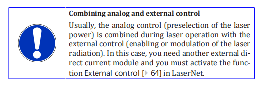
7.4.3 External control
The external control can be configured as another condition for switching on the laser radiation in the laser.

For switching the laser emission on and off via the external control, the signal Emission ON at the safety interface is used.
HIGH signal (+4 … 30 VDC) – Emission ONLOW signal (-3 … + 2 VDC) – Emission OFF
This signal can be used for modulation of the laser radiation. This re-quires a signal generator that outputs a square wave. The laser radiation can be modulated with a frequency up to a maximum of 5,000 Hz.
For more information about the safety interface, see the supplied technical data.

To operate the laser via the external control, do as follows:
- Establisha connection to LaserNet, if this has not already been done (see TEST mode [} 62]).
- Connect the external control to the safety interface (for the pin assignment of the safety interface, see the supplied technical data).
Activating the external control
3. Open the Control tab [} 97].
4. Click on the button External control OFF (8).
The button then changes its status to ON. The external control is activated.
- Click on the button LaserOFF (5).
The button then changes its status to ON. The laser power supply switches on.
- Set the laser power (TEST mode [}62]).
- Click on the button EmissionOFF (6).
- Set the signal Emission ON of the external control to HIGH.
The laser radiation is enabled. The laser emits the preselected laser power.
You can change the power at any time using the slider (2) or directly entering a newvalue.
Deactivating the
external control
9. Set the signal Emission ON of the external control to LOW.
10. Click on the button Emission ON (6).
The laser emission stops.
- Click on the button LaserON (5).
The laser power supply switches off.
7.4.4 Analog control
With the Analog control function, you can define the preselected power via the analog interface.
The function is also available in ROBOT mode(see interface description in the supplied technical data).
To use the Analog control function, a direct voltage signal of 0…10 VDCmust be present at the analog interface (see supplied technical data).
This signal can be used for modulation of the laser power. This requires a signal generator.
To define the power preselection via the analog interface, do as follows:
- Establisha connection to LaserNet, if this has not already been done (TEST mode [} 62]).
- Open the Control tab [}97].
Activating the
analog control
3. Press the button Analog control OFF (10).
The button then changes its status to ON. The analog control is activated.
4. Click on the button Laser OFF (5).
The button then changes its status to ON. The laser power supply switches on.
- Select the laser output power via the analog interface (see supplied technical data).
An input voltage of 0 VDC corresponds to a laser power of 0 W, 10 VDCcorresponds to the nominal output power.
The laser power can be setvia the signal Analog control. The exact setting range of the laser power can be found in the supplied technical data.
- Click on the button Laser emissionOFF (6).
The button then changes its status to ON. The laser radiation is enabled. The laser emits the preselected laser power.
You can change the power at any time via theconnected input voltage of the analog interface.
- Click on the button Laser emissionON (6).
The button then changes its status to OFF. The laser emission stops.
- Click on the button LaserON (5).
The button then changes its status to OFF. The laser power supply switches off.
7.5 ROBOT mode
- Followthe steps described in the section Switching on/off [} 59] to switch on the laser in ROBOT mode.
- Establish a connection to the laser, if this has not already been done (Establishing a connection to the laser [} 74]).
- Start the LaserNet software (Starting LaserNet [}76]).
The LaserNet software is used for monitoring the laser operation. All LaserNet buttons, incl. the buttons Reset and E-Stop are disabled.
This can also be deactivated, if necessary. Detailed information about the LaserNet software can be found in the section (LaserNet software[} 70]).
Checking the
beam path
After maintenance work and a prolonged shutdown of the laser, the
beam path must be checked with the help of the guide laser.
The guide laser switches on. The corresponding signal is sent back from the laser to the robot as confirmation.
- Check whether the guide laser is visible at the outlet of the process optics and has no irregularities. You can do this, for example, by holding a white sheet of paper in front of the process optics and looking at the laser spot.
- Contact the responsible IPG service department if the laser spot at the outlet of the process optics is invisible or exhibits irregularities such as dark spots. Do not turn on the laser emission if this is case.
Laser program
To enable laser radiation in ROBOT mode, a laser program (program
nos. 1–50) must be specified. Laser programs can be created via the
program editor LaserNet software and stored in the internal memory of
the laser (see section LaserNet program editor [} 106]). If no laser pro-
gram has been set, laser program 0 is automatically activated. In this
case, the laser is emitted using the preset laser power as soon as the
corresponding signal has been applied. Upon removal of the signal, the
laser emission is interrupted.
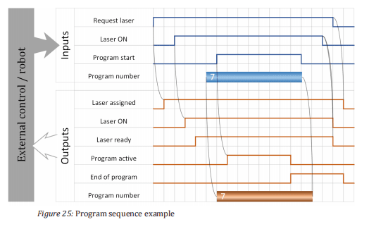
General program
sequence
6. The input signal Request laser will be sent by the external operator control of the laser. Without this signal, all other input signals
that may be set will be ignored.
As output, the signal Laser assigned is set by the laser.
- The input signal Laser ON switches on the laser power supply.
As output signal, Laser ON is sent when the laser power supply has been switched on successfully and has reached its nominal output voltage.
If no failures are active, the laser outputs the signal Laser ready.
- The input signal Program number selects a laser program.
As an output signal, Program number is sent as confirmation.
- The input signal Program start enables the laser emission.
If no program number is set, the laser operates with program number 0.
In this case, the output power must be set via LaserNet or an externalinterface (analog interface or fieldbus).
The laser emission remains enabled as long as the signal Program start is set or until the signal Program stop is sent.
As long as a program is active, the laser sends the output signal Program active. When a program is finished, the laser sends the output signal End of Program.
If a program was interrupted unexpectedly by a failure, the laser sends the output signal Program interrupted.
Program sequence example
8 LaserNet software
The software LaserNet is included with the laser. You can operate and monitor the laser with the help of LaserNet.
Fast Ethernet 100 Mbit/s isused as the interface between the computer and the laser.
8.1 System requirements
In order that you can operate the LaserNet software on your PC, the following system requirements must be met:
- PentiumIII/IV 1 GHz or compatible (recommended – Pentium IV 2 GHz)
- RAM 256 MB (recommended 512 MB)
- Screen resolution 1024х768 (XGA) 256 colors (recommended – True Color)
- Ethernet 100 Mbit
- CD/DVD drive (only for installation)
- Operating system Windows 2000 / XP / VISTA / 7 / 8 / 10
8.2 Installing the software
The installation wizard installs the software on your computer and places a shortcut on your desktop for starting the software, if desired.
- Insert the installation CD into the CD drive of your computer.
- Open the folder LaserNetSetup.
- Double-clickthe LaserNet Setup.exe installation file to open the installation wizard.
- Click on Next .

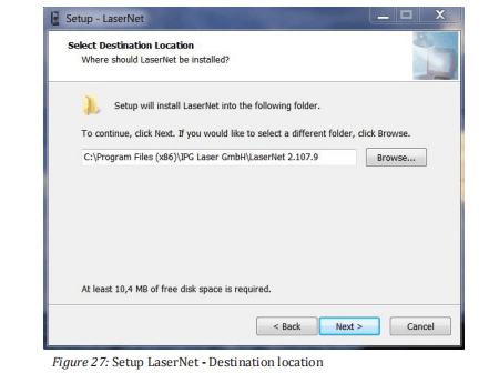
- Select the installation location for the software and click onNext .
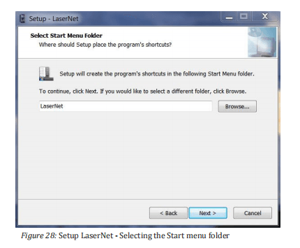
- Select a name for the Start menu folder and confirm with Next .
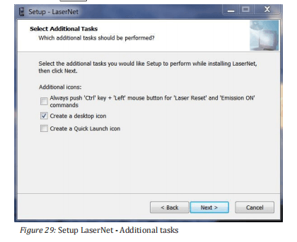
- Click on Next .
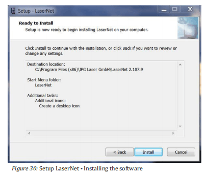
- Click on Install to start the installation.
- Click on Finish to finish the installation.
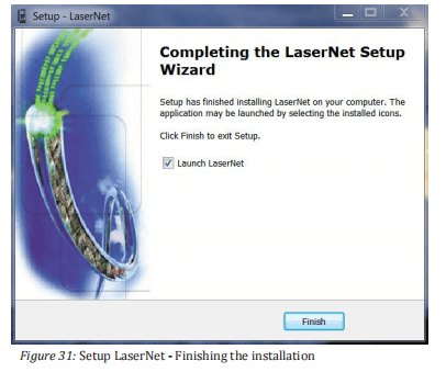
- Keep the option Launch LaserNet selected, to start LaserNet after the Installation is finished.
LaserNet is now installed on your PC.
8.3 Establishing a connection to the laser
In order that you can establish a connection between your computer and the laser, you must connect the computer and the laser to the same local network.
Proceed as follows:
- Connecta network cable to the corresponding interface of the laser and to the network card of your computer.
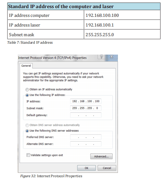
- Inthe Windows operating system, open the dialog window Internet Protocol Properties(TCP/IPv4) and enter there the standard IP address of the computer (see table and Fig. Inter- net Protocol Properties)
- Change the last 3 digits of the IP address. Note that the IP address of the laser and the computer must differ in the last three digits.
- After entering the IP address, click on OK.
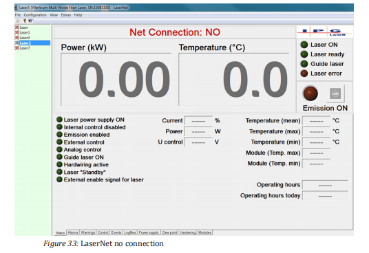
- Start the software by double-clicking the LaserNet.exefile or its link LaserNet[VERSION].
The following screen appears.
- Click in the menu bar on the menu Configuration.
A drop down menu appears.
- In the drop down menu, select the submenu IP Configuration.

- In the IP Configuration dialog window, click on the button Add to create a laser name.
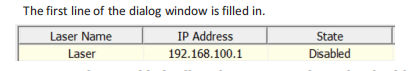
- Activatethe Disabled cell in the State column by double-clicking on it.
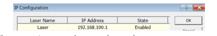
A drop down menu appears.
- Click in the drop down menu on Enabled to activate the laser.
- Click on OK.
The connection may take several seconds.
As soon as the connection between the laser and the program has been established, the connection status in the LaserNet user interface changes from Net Connection: NO to Net Connection: OK.
8.4 Starting LaserNet
- Before starting LaserNet, make certain that the laser and computer are connected to the same local network (LAN) and configured appropriately.
- Start the software by double-clicking the LaserNet.exefile or its link LaserNet[VERSION].
The connection may take several seconds.
The window of the Status tab appears.
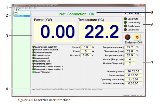
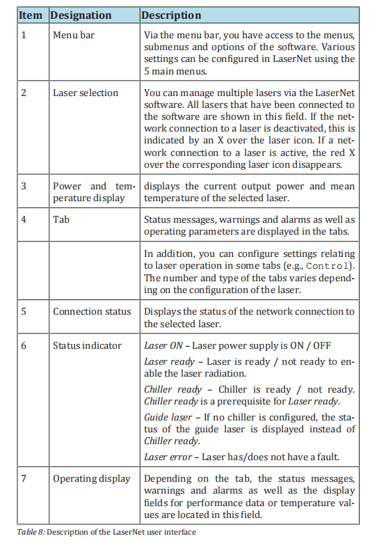
8.5 LaserNet user interface
The figure below shows the user interface of the LaserNet software. The table contains a brief description of the main information elements of the software.
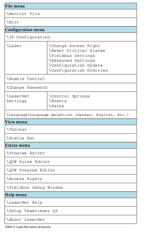
8.6 LaserNet menu description
The table below provides an overview of the LaserNet menu structure.
A detailed description of the individual menus can be found in the following sections of this operating manual.
8.6.1 File menu
Monitor file
In the submenu Monitor File, you have the option of recording selected
signals. This recording can be used later for failure analysis.
To record the signals, do as follows:
1. Place a check mark in front of each signal you would like to
record.
2. Set the scanning period using the drop down menu Period.
3. Place a check mark in front of the field Enable the recording of the
monitor file.
4. Activate the recording by clicking on OK .
The resulting file is stored in the format *.txt. The file storage location is specified
in theConfigurationLaserNet SettingsPaths menu under Path
to log files(see Section Configuration menu [} 89]).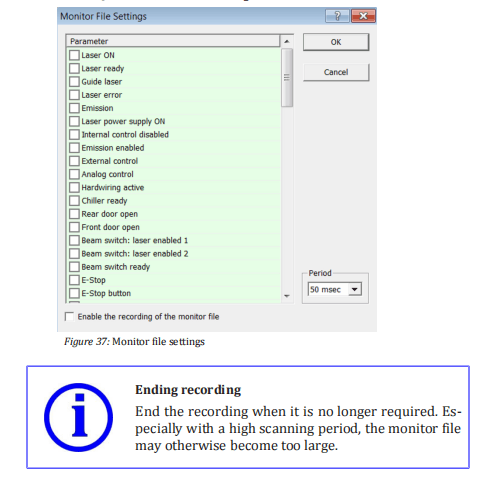
ð Remove the check mark from the field Enable the recording of the monitor file to end the recording of the monitor file.
Exit
You can close the LaserNet software via the Exit submenu.
8.6.2 Configuration menu
IP Configuration
In the submenu IP Configuration, you can change the laser name and the
IP address of a laser as well as activate or deactivate a laser.
The laser name is used for identification if you control and monitor multiple lasers with one computer.
Ensure that you assign each laser a unique name. In the IP address column, the IP address for the laser withthe corresponding name is assigned.
If an active connection to a laser exists, the button IP Properties becomes available (only in Supervisor Mode).
Clicking on this button opens an input window in which you can change the IP address of the laser.

Laser Change
Access Right
In the submenu Change Access Right, you can change between four dif-
ferent password-protected access levels. The following access levels are
available:
• Monitoring
• Operator
• Engineer
• Supervisor
The currently selected access level is marked with a check mark. The various user rights can be viewed via the menu path ExtrasAccess Rights.
When changing from one access level to another, a password must be
entered. By default, no password is set. However, the Supervisor can set and change passwords for all access levels via the menu path ExtrasAccess Rights.
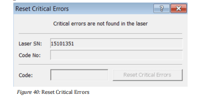
Laser Reset Critical Errors
If the laser reports the alarm Critical error, you cannot reset the error
by pressing the Reset button. You can only reset a critical error by entering a code.
The code can be obtained by contacting the competent IPG service department (see Resetting critical errors [} 139]).
Laser Fieldbus
Settings

Before you can work with your fieldbus interface, you must configure some parameters via the LaserNet software during initial commissioning.
If you are using a multiport interface, you must set the corresponding parameters for every fieldbus card during the initial start-up.
The parameters are described briefly below.
Address
In this field you can define the slave address for fieldbus cards with the appropriate option (e.g., Profibus).
If a master accesses multiple slave cards, the slave cards must have different addresses.
If multiple independent masters access different slave cards, the slave cards can have the same MAC ID.
Endianness
In this field, you can set the endianness for communication (little-endian – big-endian). You can set the byte order for communication separately for each slot.
Enabled optical channels
(Option depends on configuration)
In this field, you can enable the optical channels for the respective slot(slave card). Only selected optical channels can be requested and used by the respective slot. You can assign multiple slots, i.e. slave cards, to a channel.
Channel number
(Option depends on configuration)
These fields display the current coding for each optical channel of the beam switch.
The coding corresponds to the optical path that must be requested by the system owner’s PLC unit.
If the first optical channel of the beam switch was coded with the value 10, the PLC unit must set optical path number 10. The coding is performed in the laser.
Laser number
The current coding of the laser is shown here.
The encoding corresponds to the laser number which must be requested from the operator-side PLC unit if the check box Checkin the Laser number group box has been activated.
If the laser is coded with value 6, the PLC unit was set laser number 6. The coding is performed in the laser itself.
Check
If this option is activated, the laser control checks whether the right laser number is sent by the system owner’s PLC unit. If the laser number is not correct, the laser reports a failure.
Laser program number
If you activate the option Laser program number, the input signal of the external control Laser program number is immediately reported back to the external control.
Otherwise, the laser program number is only reported after receipt of the signal Program Start along with the execution of the program.
Update configuration file
Clicking this button opens a file browsing window with which you can upload an update file (dbm format) for configuration of your Profinet slaves.
This update file can be obtained from IPG Laser GmbH upon request.
Advanced settings
Clicking this button opens an input window in which you can change various parameters depending on the available fieldbus interface.
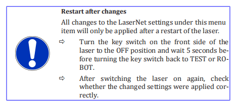
Laser Advanced
Settings
Automatic Switching OFF
In the submenu Advanced settings, you can set the laser emission time
of the laser. To do this, enter the desired emission time in the input field
Max. Emission Time (see figure below). The laser emission will stop after the configured time has elapsed, starting from the time at which the
status Emission enabled was activated. If you activate the De-energizing
of power supplies field, the main power supply will also switch off as
soon as the laser emission stops. The Automatic switch-off function is
deactivated if you enter zero (0) seconds into the input field Max. Emission Time.
Feeding Fiber Option
(Option depends on configuration)
With this function, you can select whether to work with the installed integrated optics (if present) or directly with the feeding fiber.
Operator power display adjustment
You have the option of displaying the actual power measured at the output of the process optics within the LaserNet user interface in the power display area (see the figure below). To change the power display,proceed as follows:
- In the check box, click enable.
- Click on the button Customization .
An input window appears.

- Enter the measured power value in watts.
- Click on OK .
The value entered by you will appear in the power display field. An as-terisk will appear above the power display field (see figure below) toindicate that this option is active.
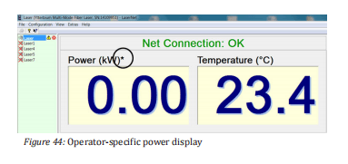
Remote Support
This option allows the competent IPG service department to access the laser (events, warnings, errors, etc.).
Laser Configuration Update
Via the submenu Configuration Update, you can perform an update of
the laser configuration as well as the firmware. Clicking on the submenu
opens a file browsing window. In this browsing window, you can select
the update file (*.hplp) to be loaded. The update file can be obtained
from IPG Laser GmbH upon request.
Laser Configuration Overview
In the submenu Configuration Overview, you will find information about
the laser (e.g. serial number, ID, firmware) as well as about the laser
configuration (e.g. parameters, options).
Enable Control
Activate this option to apply password protection to all operating functions in LaserNet in order to prevent unauthorized access.
Change Password
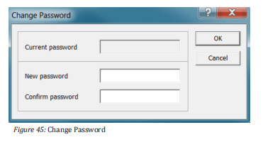
In this dialog window, you can set a computer-specific password forLaserNet, independent of access rights.
Activating the password willlock out the LaserNet operating elements on the Control tab.
This lock can be removed by entering the password via Configuration Enable Control.
If you lose this password, it is possible to delete it. To do this, proceed as follows:
1) Open the “Registry Editor”. The value “user” is stored under the following path: HKEY_Current_UserSoftwareIPG Laser GmbH LaserNet Settings
2) Delete the value “user”.
3) Restart LaserNet.
You can now create a new password or work with LaserNet without password protection.

LaserNet Settings
Control Options
With the dialog window shown below, you can enable or disable control
options in LaserNet.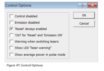
ð Place a check mark in the corresponding field to enable an option.
The following table contains a short description of the control options.
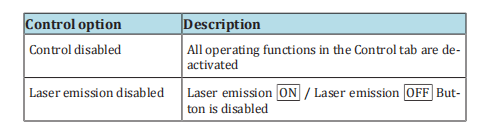
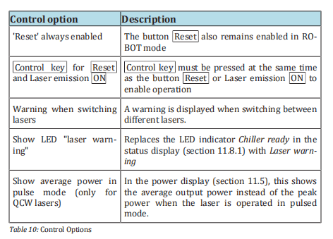
LaserNet Settings
Events
In the dialog shown in the figure below, you can define the maximum
number of events that should be saved in the file events4.dat. This allows you to limit the file size.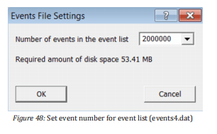
LaserNet Settings
Paths
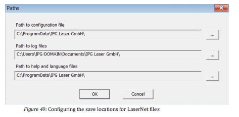
In this submenu, you can configure the save locations for the following files:
- Configuration file
- Log files
- Help and language files
The table below provides an overview of the default settings.
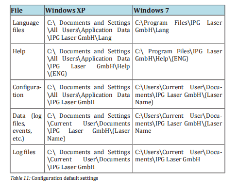
Language
In the submenu Language, you can select the desired language for
LaserNet. If language options are displayed as □□□, the corresponding
library file is not installed under Windows.
8.6.3 View menu
Status Bar
Enable/disable this option to show/hide the status bar.
Toolbar
Enable/disable this option to show/hide the toolbar.
8.6.4 Extras menu
Program Editor
In the submenu Program Editor, you can create and edit laser programs.
A detailed description of the LaserNet program editor can be found in chapter LaserNet program editor [} 106].
QCW Pulse Editor
Via the submenu QCW Pulse Editor, you can create and edit pulse forms.
The pulse forms are stored as pulse form libraries, which must be
loaded before use in LaserNet.
This option is only available for QCW lasers and is further described in the
corresponding chapters below.
QCW Program
Editor
Via the submenu QCW Program Editor , you can assign the pulse forms
to one of the laser programs.
This option is only available for QCW lasers and is further described in the corresponding chapters below.
Access Rights
In the submenu Access Rights, you can set rights for the various LaserNet access levels. In addition, you can set or change the passwords for
the access levels. No passwords are assigned by default.
- Clickon the button Passwords to open the input window for changing the passwords.
A dialog window appears.
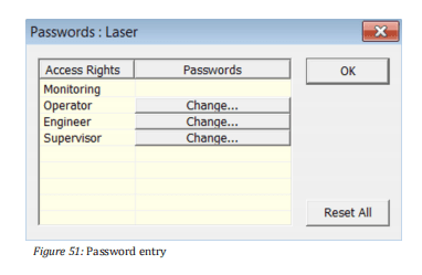
2. Click on the button Change for the access level to change the
password.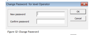
- Enter the new password and confirm with OK .
Fieldbus Debug
Window
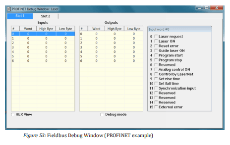
In the submenu Fieldbus Debug Window, the communication between master and slave is displayed.
If the debug mode is activated in this submenu, all fieldbus output bits can be set manually. In this case, the laser will not respond to input bits.
If debug mode is not activated, no outputs can be set manually.
8.6.5 Help menu
LaserNet Help
The submenu LaserNet Help opens the LaserNet offline help (if installed).
Setup
Teamviewer QS
Via the submenu Setup Teamviewer QS, you have the option of allowing
service technicians of IPG Laser GmbH to access your computer.
About LaserNet
The submenu About LaserNet shows the version number of the cur-
rently installed LaserNet software.
8.7 LaserNet status indicators
LaserNet uses three different LED indicators. The LED indicators are listed and explained in the following table.

8.8 LaserNet tabs
The tabs shown in this section provide examples in order to describe the LaserNet software.
The type and number of the tabs as well as the status, warning and fault messages shown vary based on the configuration of the laser.
8.8.1 Status tab
This tab displays status messages and actual values of the laser.
The green status LED indicator , which is shown in front of every status message, indicates whether a status message is active or inactive
(LaserNet status indicators [} 93]). A detailed description of the statusmessages can be found in the appendix under Messages of the Statustab.
The actual values are described briefly below.

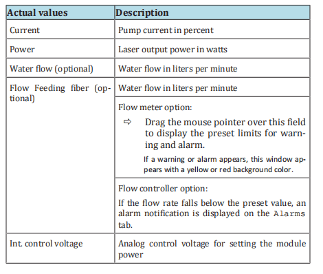

8.8.2 Alarms tab

Alarms of the laser are displayed on this tab (see figure above).
A detailed description of the individual alarms as well as instructions for eliminating the faults can be found in the appendix under Messages of the Alarms tab.
8.8.3 Warnings tab

Warnings of the laser are displayed on this tab (see figure above).
In contrast to alarms, warnings do not interrupt the laser operation. A more detailed description of the individual warnings as well as instructions for eliminating them can be found in the appendix under Messages of the Warnings tab.
8.8.4 Control tab

The buttons on this tab (see previous figure) reflect the current status
of the laser or allow you to configure various settings relating to laser
operation. If the laser is in ROBOT mode, all buttons (except Reset ) are
grayed out (i.e., disabled) by default.
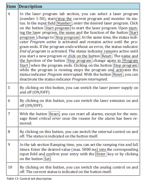
8.8.5 Events tab
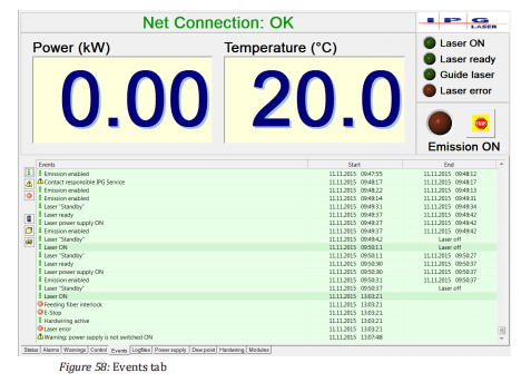
All events of the laser are listed on this tab (see figure above).
The symbols on the left serve as filters. You can activate or deactivate
the display of the respective events by clicking on them.
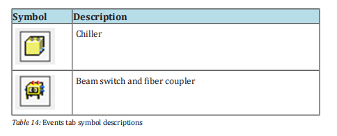
Via the context menu (right-click in the Events column), you can also:
- Sort the events by time
- Save the events as a .txt file
- Delete the events
You limit the number of saved events under the path ConfigurationLaserNet SettingsEvents.
Once you close LaserNet, the events are saved in the file events4.dat in the directory IPG LaserLasername.
8.8.6 Logfiles tab
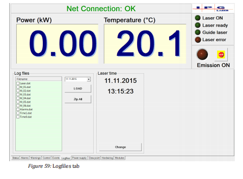
In this tab (see figure above), you can select and download the created log files. The log files are saved in the laser memory.
In event of a fault,you can download the corresponding files to your computer and send them to the competent IPG service department.
To download the files, proceed as described in the section Downloading the log files via LaserNet [} 131].
8.8.7 Power supply tab
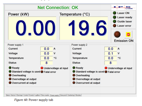
On this tab (see previous figure), the actual values as well as status messages and alarms of the installed laser power supplies are displayed.
A detailed description of the individual status messages and alarms as well as instructions for eliminating the faults can be found in the appendix under Messages of the Power Supply tab.
The displayed actual values are described in the table below.
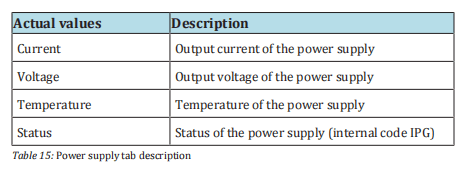
8.8.8 Chiller tab
Actual values of the laser chiller are displayed in this tab (see Fig. Chiller Status tab).
IPG chiller
The status messages, warnings and alarms of the chiller can be accessed
via the side tabs (see Fig. Alarms and Fig. Warnings). A detailed descrip-
tion of the individual alarms and warnings as well as instructions for
eliminating the faults can be found in the appendix under Messages of
the Chiller tab.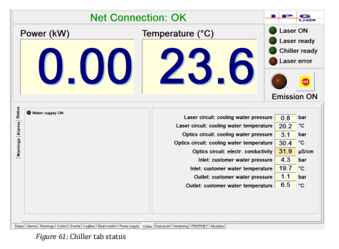

8.8.9 Dew point tab

Warnings and alarms as well as actual values concerning the dew pointare displayed on this tab.
A more detailed description of the warnings and alarms as well as instructions for eliminating the faults can befound in the appendix under Messages of the Dew Point tab.
The displayed actual values are described in the table below.
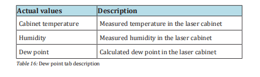
8.8.10 Hardwiring tab

This tab shows the status of the input and output signals of the hardwiring interface.
For a detailed description of the signal of the hardwiring interface, use the supplied technical data.
8.8.11 Modules tab

The Modules tab (see figure above) contains status information about
the installed laser modules. You can activate or deactivate individual
modules. The central elements of this tab are described in the table below.
8.9 LaserNet program editor
With the program editor of the LaserNet software, you can create up to 50 custom laser programs.
The program editor can be opened via thepath Menu ExtrasProgram Editor.

8.9.1 LaserNet program editor editing window
The figure below shows the editing window of the program editor. With this window, you can open and edit or create a new laser program (LP).
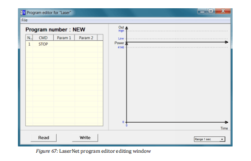
Commands are entered in the input field on the left side of the user interface; on the right side, the program is displayed in the form of a diagram (laser output power / time).
Column 1 (No) of the input field shows the command number, column 2(Command) the command itself.
Upon opening the program editor, the command STOP is listed in line 1 by default.
In the columns 3 (Param1)and 4 (Param2), you can enter the parameters for each command.
You can enter the commands and parameters either via the key board or via a drop down menu.
The drop down menus for the columns 2, 3 and 4appear as soon as you click on the field.
ð A new line can be inserted either by left-clicking on any open line or right-clicking on an existing line (the option “Insert line” appears).
The default command “STOP” automatically appears in the new line, but this canbe changed to any command.
ð To delete an existing command line, right-click on the corresponding line and select the option Delete line.
If the laser program consists of only a single line, this cannot be deleted.
ð To save a laser program in the laser, click on the button Write .
A dialog window appears. Here you can assign the laser program a number between 1 and 50 and save the program under this number.
Assigned program numbers have a red background, available program numbers are green.
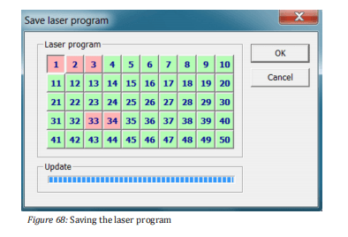
ð To load a previously saved laser program, click on the button Read (see Fig. Editing window) and select the desired program number (1-50).
After loading the laser program, the current program number in the title of the table is shown in the editing window.
You can also save a laser program as a file on the computer.
ð To do this, click in the program editor on the menu File and then on Save (see Fig. Editing window).
Enter the path of the save location and the file name, then click on Save .
The program file is stored as a text file with the extension “.Inp” and can be viewed and modified in any standard text editor.
ð To load a laser program that you have saved on your computer as a text file, click in the program editor on the menu File and then on Open.
Select the desired file.
8.9.2 Command list for laser programs
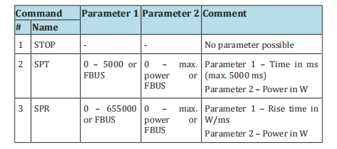
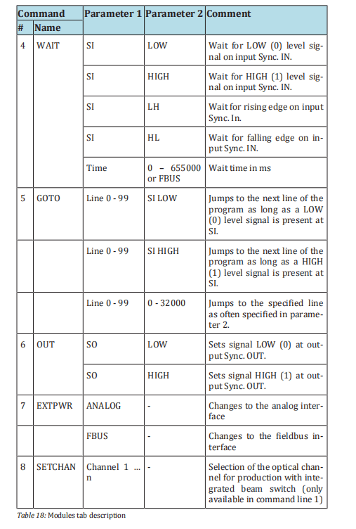
8.9.3 Laser program editor command descriptions
STOP
The STOP command must be set as the last command of a laser program. This command does the following:
• Switches off the laser emission.
• Switches off the analog control.
• Stops execution of the laser program.
• Sets the status End of Program to HIGH.
SPT
Define the emission power over a period of time
Linear ramp function: Switches the laser emission on and defines thepower to be reached within a specific time.
Parameter 2 defines the power [W], parameter 1 defines the time [ms],in which the power will be reached.
The parameters can be assigned in the following ways: • Manual input as numerical value in the program editor • Via the fieldbus interface (FBUS)
If a previous command switched on the laser emission and set the laser power, the laser power of this command is used as the initial power for the command SPT; otherwise the initial power is zero watts (0W).
The command SPT stops the execution of the command EXTPWR if thiswas previously switched off.
SPR
Define the emission power over a ramping time
The command has a function similar to the SPT command (see description above).
Linear ramp function: Turns the laser emission on and defines thepower to be reached over a defined ramping time.
Parameter 2 defines the power [W], parameter 1 defines the power increase (ramping time) [W/ms] with which the specified power will be reached.
WAIT
Wait for event
Parameter 1 defines the event type:
- Synchronization signal Sync. In
- Time [ms] Time
Parameter 2 determines the event:
- Falling edge
- Rising edge
- State LOW
- State HIGH
- Expiration of the wait time [ms]Time
- The parameters can be assigned in the following ways:
- Manual entry in the program editor
- Via the fieldbus interface (FBUS) for the event type Time.
GOTO
Goto command
Jumps to the defined command line and executes all subsequent com-mands up to GOTO in a loop.
Parameter 1 indicates the number of the command line (0 – 99) as of which the command set should be executed again.
Parameter 2 determines the event:
- SIHIGH: The command set defined in parameter 1 will be executed as long as the signal HIGH is present at the synchronization input.
- SILOW: The command set defined in parameter 1 will be executed as long as the signal LOW is present at the synchronization input.
- Counter(0 – 32767):Number of repetitions of the command set to be executed. With a value of 0, the defined command set is executed in an endless loop.
OUT
Set signal “Synchronization Output”
- Sets signal LOW or HIGH at the output Sync. Out
- Parameter 1 selects a synchronization signal
- Parameter 2 sets the level (HIGH / LOW)
EXTPWR
Switch to external mode
This command specifies the external interface from which the value foremission power and the time should be read for the commands SPT,SPR and WAIT.
The execution of this command can be stopped with the commands STOP, SPT, SPR and EXTPWR (by selecting a different external interface).
SETCHAN
Selection of the beam switch channel
This command selects the optical channel for production with integrated beam switch.
The command can only be executed in the first line of the program.
SETCHAN is only available for lasers with a beam switch.
9 Maintenance

ð Immediately after finishing the maintenance work, restore or activate all safety and protection equipment.
ð Check the correct connection of all safety-related components.
IPG Laser GmbH recommends that the listed maintenance work be performed at the specified intervals.
9.1 Maintenance work
9.1.1 Clean fiber connectors
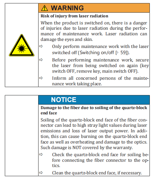
Before inserting the fiber in the optics (e.g., during installation, fiber or
optics replacement), the fiber connector must be checked for contamination and cleaned as required.
Notes about
cleaning
ð Only use the cleaning materials described in this operating man-
ual.
ð Only follow the cleaning procedure described in this operating manual.
ð Never touch the quartz-block end-face or the glass surface of the
screwable protective sleeve with your fingers.
Required materials
You need the following materials for the cleaning:
• Lint-free cleaning swabs
• Isopropanol (anhydrous)
• Acetone (anhydrous)
• Compressed air (oil-free, anhydrous)
• Microscope, model IPG or similar
• Light-source
The cleaning swabs are included in the scope of delivery. The microscope and compressed air are included with the order.
Preparation
1. Ensure a clean working place close to the process optics. Then
minimize the risk of a re-contamination of the fiber connector after the cleaning process.
2. Keep a clean protective cap available for the process optics.
3. Remove any impurities within the protective cap with compressed air as a precaution before use.
4. After cleaning, place the protective cap on a clean storage surface
with the open side down.
5. Place the microscope on a level surface to ensure a secure base of
the microscope.
6. Use a damp cloth to remove coarse dirt from the fiber connector
and the optics near the fiber connector.
7. Alternatively, you can remove the coarse dirt with compressed
air. After compressed air usage, wait a while until any dispersed
dust has settled before you disconnect the fiber connector from
the optics.
8. Disconnect the fiber connector from the optics (see the following
figure). To unlock the bayonet mount, turn the grooved handle
counterclockwise until the stop (1). Pull the fiber connector carefully off (2).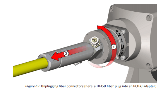
- Immediately seal the optics with the cleaned protective cap.
- Place the fiber connector in the holder on the microscope (see figure Microscope).
- Switch the microscope’s light source on and point this towards the surface to be cleaned.
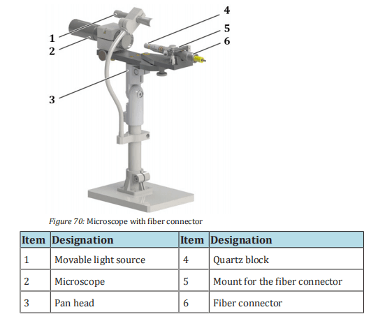
Cleaning
Quartz block protection
Depending on the fiber connector option, the fiber connector may be fitted with a protective conduit or glass to protect of the quartz block (see the following figure).

Depending on the area of application and the required laser power, it
may be necessary to unscrew the protective glass or protective conduit.
The following tables determine for which applications and usage conditions the quartz block protection may be used.

The cleaning steps differ depending on whether a protective conduit ortube is used.
For fiber connectors without quartz block protection or with a protective conduit, the quartz-block end-face is cleaned; for fiber connectors with protective glass, only the protective glass is cleaned, ifthe quartz block end surface is free from debris.
In case of persistent dirt accumulation, the protective glass may be replaced with new protective glass.
Optional protective conduit
- Remove the screwed-on protective conduit and place it on a clean surface. A clean, lint-free cloth is ideal for placing the protective conduit on.
- Adjust the focus of the microscope to the quartz-block end-face.
- Checkthe quartz-block end-face for impurities (e.g. dark points). If you find impurities on the quartz-block end-face, perform the following steps.
- Removea cleaning swab from the package without touching the wadding of the stick.
- Moisten the cleaning swab with a drop of isopropanol.
- Shake off excess isopropanol from the cleaning swab.
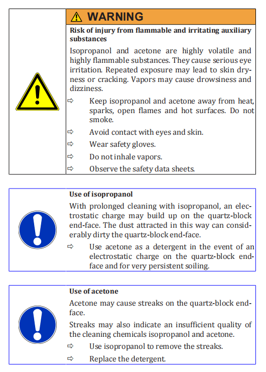
18. Look through the microscope and swipe over the quartz-block
end-face on the fiber connector with a light pressure.
19. After 20 seconds at most, replace the cleaning stick if the cleaning
is to last longer.
20. Clean the protective conduit with compressed air outside of the
cleaning station and screw this back onto the fiber connector once
the cleaning of the quartz-block end-face is completed. Do not
touch the quartz-block end-face in the process.
21. Check the quartz-block end-face again for impurities. If necessary,
repeat the cleaning process.
- If the quartz-block end-face is clean, remove the fiber connector from the microscope and take this to the optics immediately. Ensure that the quartz-block end-face is facing downwards during the process.
- Remove the protective cap from the optics.
- Plug the cleaned fiber connector promptly and carefully into the optics (see the following figure). Align the markers on the fiber connector (A) and optics holder (B) with each other (1) and carefully slide the fiber connector up to the stop into the optics (2).
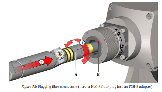
- Turn the large pin on the bayonet mount from position 1 marked on the adapter to position 2 (step (3) in the figure below).
- Lock the bayonet mount by turning the grooved handle clockwise (4) as far as the stop.
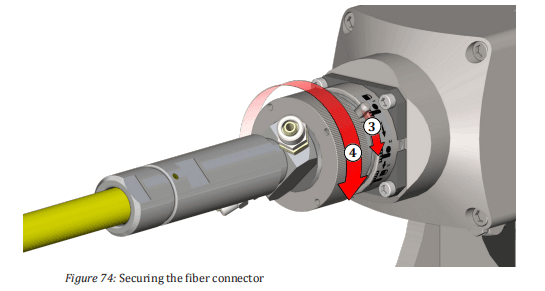
Protective glass option
- Adjust the focus of the microscope to the quartz-block end-face (third focusing plane).
- Ifthere is dirt on the quartz-block end-face, remove the screwed- on protective glass and follow the cleaning steps described under the protective conduit option.
- If the quartz-block end-face does not exhibit any impurities, adjust the microscope’s focus to the protective glass surface (first focusing plane).
- If the protective glass is dirty, perform the cleaning similar to the cleaning procedure described under the protective conduit option.
- Alternatively,replace the dirty protective glass for a clean protec- tive glass. In doing so, ensure that no dirt is situated on the quartz-block end-face. Do not touch the new protective glass with your fingers. Use the white protective packaging in which the pro- tective glass was delivered in order to screw the new protective glass onto the fiber connector.
9.1.2 Measuring the laser output power
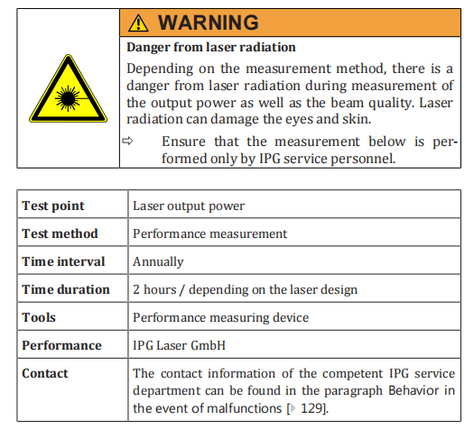
9.1.3 Measuring the beam quality
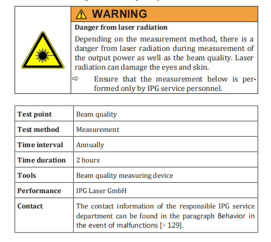
9.1.4 Checking the water outlet
The product is equipped with a water drain with a water-soluble membrane in the cabinet bottom.
In the case of a leakage inside the laser, the membrane dissolves and the water can flow out through the waterdrain.
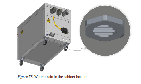
If the membrane is missing, the seal of the cabinet is impaired so that the correct microclimate inside the cabinet can no longer be guaranteed.
ð Check the integrity of the membrane at least once per year or if there is reason to suspect that the membrane was damaged, such as by water spray.
The absence of the membrane is often associated with the alarm message Dew point temperature too high.
ð Proceed as follows to check the integrity of the membrane.
- Removethe eight M5 counter sunk screws on the left cover of the laser cabinet.
- Carefully move the left cover to the side.
The left cover is connected to the frame of the laser cabinet by a grounding wire.The grounding wire is affixed to the grounding connector (star connector) with aflat connector.
- Unplug the flat connector of the grounding line from the grounding connector on the frame.
- Remove the left cover.
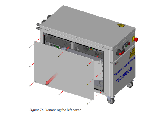
- Lookthrough the membrane mount, and check whether the membrane is present and undamaged.
The membrane is a replacement part and is delivered in an assembly together with the membrane mount and the membrane holder.
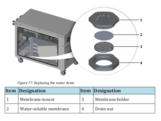
If the membrane is damaged or not present, the entire membrane assembly consisting of the membrane mount, the membrane holder and the membrane itself must be replaced. To do this, proceed as follows:
- Hold the drain nut in place while unscrewing the membrane mount counter clockwise (wrench size 40 mm).
- Remove the damaged membrane assembly.
- Screwin a new membrane assembly with an undamaged membrane, turning clockwise.
- Fasten the grounding line of the left cover back on the grounding connector, and screw the left cover firmly to the laser cabinet.
9.2 Replacement and repair work
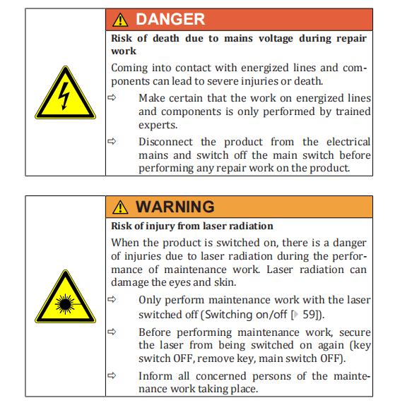

9.2.1 Replacing a laser module
| Test point | Laser modules |
| Test method | Performance measurement |
| Time interval | In the event of a failure |
| Time duration | ~ 3 hours |
| Performance | IPG Laser GmbH |
| Contact | The contact information of the competent IPG service department can be found in the paragraph Behavior in the event of malfunctions [} 129]. |
9.2.2 Replacing the feeding fiber
| Test point | Feeding fiber |
| Test method | Measurement of the transmission and beam quality |
| Time interval | In the event of a fault |
| Time duration | ~ 5 hours |
| Performance | IPG Laser GmbH |
| Contact | The contact information of the competent IPG service department can be found in the section Behavior in the event of malfunctions [} 129]. |
9.3 Maintenance of the water system (IPGchiller)
Information for maintenance of the water system can be found in the operating manual of the laser chiller.
10 Messages and troubleshooting
10.1 Information about message displays
All laser-related warnings and errors that occur during laser operation are displayed as active LED Indicators in the tabs Warnings (Warnings tab [} 96] and Errors(Alarms tab [} 95]) of the software LaserNet.
In the event of a warning, an LED indicator in the Warnings tab lights up. The laser remains in operation.
If there is a laser-related malfunction, the LED display Laser error lights up red and the green LED indicator Laser ready goes out.
Any laser emission is stopped immediately.The corresponding LED indicator for the alarm lights up in the Alarms tab.
Possible failures of an external or built-in laser chiller do not necessarily lead to switching off the laser emission.
ð Detailed information about the individual messages can be found in the tab Events.
To put the product back into operation after eliminating the problem,the alarms must be reset.
For some messages, this takes place automatically; for all other messages, you must click the Reset button in the Control tab (Control tab [} 97]).

10.2 Status messages, warnings and alarms
Information about the status messages, warnings and alarms is collected in Appendix A.
10.3 Troubleshooting
Detailed information on troubleshooting can be found in Appendix A.

10.4 Manufacturer’s service
10.4.1 Behavior in the event of malfunctions
In the event of errors that cannot be rectified using this operating manual, please contact the competent IPG service department
For the most comprehensive problem description, we recommend sending the following data to your competent IPG service department following prior consultation:
- Log files (Downloading the log files via LaserNet [}131])
- Anevents file as .txt file (Downloading the events file via LaserNet [} 135])
- Anoverview of the configuration (Downloading the configuration overview via LaserNet [} 136])
10.4.2 Downloading the log files via LaserNet
The log files are automatically generated by the LaserNet software and can be downloaded via the LaserNet software.
They contain information about the laser, its operating parameters, all important events and any alarms.
The laser log file Laser.dat also contains all information about the laser chiller.
Follow to the following steps to download a log file:
- Start the LaserNet software.
- Make certain that there is a network connection to the laser.
- Select the Logfiles tab.

There are two ways to save the log files:
- Save individual log files from a certain day via the Load button.
- Save all log files over a certain time period via the Zip All button.
Load
4. Select the date on which the fault occurred. If the date is not
known, you can use the Events tab to find the corresponding date.
In the File name field, a list appears with the existing log files from the selected
date. If on the selected date the laser was not switched on, no log files were gen-
erated for the date and the File name field remains empty.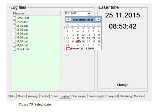
5. Using ConfigurationLaserNetSettingsPaths… select the folder in which you want to save the log files. The folder
C:UserMy DocumentsIPG Laser GmbHis selected by
default.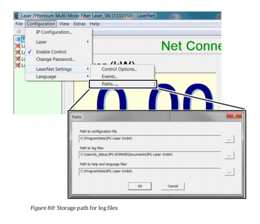
- Select the log files that you would like to download. You have two options to do this:
- Select the files individually with the left mouse button.
- Use the right mouse button toclick on the log files and in the window that appears select the Select all option with the left mouse button.
- Clickon Load to download the file to the previously selected folder.
LaserNet creates a new folder in the previously selected folder and names this according to the date from which the log files originate (e.g. 23.07.2015).
The selected files are stored in this folder.

Zip All
8. Click on the Zip All button.
The dialog window Zip All will appear.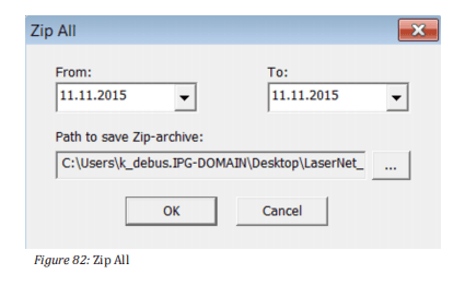
9. Specify the desired time period in the combination fields From
and To.
10. Use the … button to select the folder in which you want to save
the log files.
11. Click on the OK button.
All log files from the selected time period will be stored in the selected folder.
12. Send the downloaded log files by email to the competent IPG ser-
vice department (see Behavior in the event of malfunctions
[} 129] ).
10.4.3 Downloading the events file via LaserNet
In the Eventstab, all events reported during the laser operation arelogged and listed in chronological order.
These event messages can supply useful information about the cause of the fault and should be sent by email together with the log files to the competent IPG service department in the event of a fault.
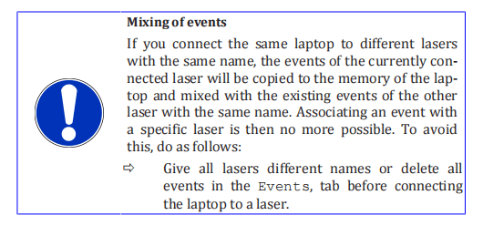
To download the events in the form of a .txt file, do as follows:
- Start the LaserNet software.
- Make certain that there is a network connection to the laser.
- Select the Eventstab.
Right-click on one of the event messages and use the left mouse button to select the option Save events to file.
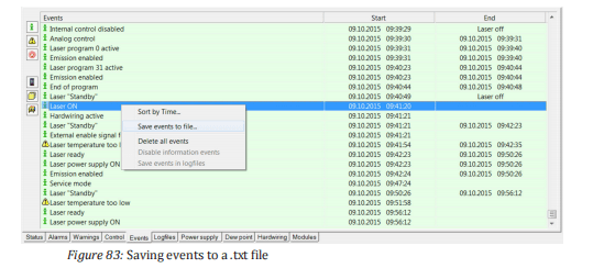
- Select the save location and click onSave .
The events file is saved. It contains the serial number of the laser in its name.
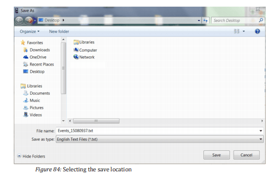
- Send the downloaded file by email to the competent IPG service department (see Behavior in the event of malfunctions [} 129]).
10.4.4 Downloading the configuration overview viaLaserNet
The configuration overview contains information about the laser, its configuration, the configured parameters and the firmware statuses of built-in components.
Follow to the following steps to download the configuration overview file:
- Start the LaserNet software.
- Make certain that there is a network connection to the laser.
- UnderConfigurationLaser select the submenu Configuration Overview.
A new window appears with the configuration overview.
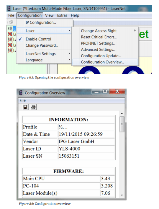
- Click on the diskette symbol in the upper left corner.
A Save as window appears.
- Select the save location and click on Save .
The configuration file is saved.
- Send the downloaded file by email to the competent IPG service department (see Behavior in the event of malfunctions [} 129]).
10.4.5 Updating the firmware and product configuration
Some faults may require a firmware update. This can be done with the help of an HPLP file. The file will be sent to you by email from the IPG service department.
Contact the competent service department of IPG Laser GmbH and describe the problem.
In order for the problem to be solved more quickly,we recommend creating a log file with LaserNet first and sending this
by email to the IPG service department (Behavior in the event of malfunctions [} 129]).
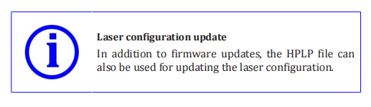
You will receive an HPLP file from our service employees with the firmware update, which can be installed using LaserNet. To do this, proceed as follows:
- Start the LaserNet software.
- Make certain that there is a network connection to the laser.
- Select ConfigurationLaserConfiguration update… .
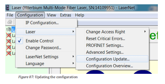
4. In the opened window, select the current HPLP file and click on
Open .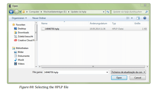
5. Wait until the new configuration is updated
- Then restart the laser.
- If an external laser chiller is used, restart this as well.
The laser software is now up to date.
10.4.6 Resetting critical errors
If the laser reports the alarm Critical error, you cannot reset the error by pressing the Reset button.
If you would like to continue working with the laser anyway, you can reset a critical error only by entering a code.
To do this, proceed as follows:
- Start the LaserNet software.
- Make certain that there is a network connection to the laser.
- Checkwhether the guide laser (guide laser 0, if a beam switch is installed) is visible at the fiber in the combiner module and at the exit of the process optics.
- InLaserNet under ConfigurationLaser, select the submenu Reset Critical Errors.
The dialog window Reset Critical Errors appears.
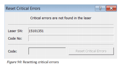
- Contact the competent IPG service department and give them the laser serial number (Laser SN) and the code number (see Fig. Reset Critical Error ) as well as the information of whether the guide laser is visible.
- Send the log files (Downloading the log files via LaserNet [} 131]) and the events file (Downloading the events file via LaserNet [} 135]) to the competent IPG service department.
An IPG service employee will provide you with the code for resetting the critical error.
The code can only be entered once for resetting the reported critical error andonly on the laser with the specified serial number.
- Enter this code into the input field Code (see Fig. Reset Critical Errors) and click on the button Reset Critical Errors .
The critical error is reset.
11 Decommissioning and disposal
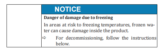
11.1 Temporary decommissioning
- Turn the key switch (if present) and switch the main switch on the front side of the product to the OFF position.
- Disconnect the power from the mains power supply and secure it against mistaken reactivation.
- Close the supply lines for water.
- Remove the connections for water.
- Drain all cooling liquid from the product.
- If a water-glycol mixture was used, dispose of it in accordance with the local regulations. The water-glycol mixture may not be allowed into the public sewer network.
- Clean up leaked cooling liquid immediately.
- Blow out all water lines in the product with oil-free compressed air.
- Close the connections for water with closing plugs.
11.2 Permanent decommissioning
- Turn the key switch (if present) and switch the main switch on the front side of the product to the OFF position.
- Disconnect the power from the mains power supply and secure it against mistaken reactivation.
- Close the supply lines for water.
- Remove the connections for water.
- Drain all cooling liquid from the product.
- If a water-glycol mixture was used, dispose of it in accordance with the local regulations. The water-glycol mixture may not be allowed into the public sewer network.
- Blow out the water circuits with oil-free compressed air.
- Clean up leaked cooling liquid immediately.
- Close the connections for water with the closing plugs.
- Remove all connections on the product.
- Remove the fiber from the process optics and protect the fiber with the provided protective cap. Note the information in chapter
Connecting the fiber connector to the process optics [} 51].
- Remove the connections to the external interface.
- Pack up all lines and hoses.
14. Bring the product and all accessories to the intended storage location until used again or until removal (Transport to the installation site [} 38]). The storage location must be dry and clean.
- Observe the storage conditions specified in the technical data.
11.3 Disposal

The following points are to be observed when disposing of the product,the accessories and the operating and auxiliary materials:
- Observe national provisions on site
- Observe company-specific guidelines
Following proper disassembly, the disassembled individual parts are to be recycled:
- Scrap remaining metallic material
- Recycle plastic elements
- Dispose of other components sorted by material property
- Ifa water-glycol mixture was used, it must be disposed of in accordance with the local regulations. The water-glycol mixture may not be allowed into the public sewer network.
Electronic waste, electronic components, lubricants and auxiliary substances (e.g. water-glycol mixtures) are subject to special waste treatment and may only be disposed of by approved specialized personnel.
National disposal regulations must be observed with respect to the environmental disposal of the product.
12 Appendix
12.1 Status messages, warnings and alarms
The laser welding tool software shows three types of messages:
- Status messages
- Warnings
- Alarms
The type and number of the messages can vary depending on the configuration of the product.
Status messages provide information about the current status of the system.
A Warning indicates the preliminary stage of an alarm. A closer look at the status or maintenance work is necessary.
An Alarm requires the elimination of the cause of the fault, adjustment work or repair / replacement of a component.
The messages that may arise during operation are describe below. Thedescriptions of the warnings and alarms also contain instructions on troubleshooting.
To put the product back into operation after eliminating the problem,the alarms must be reset.
For some messages, this takes place automatically; for all others, you must click the Reset button in the LaserNet Control tab.

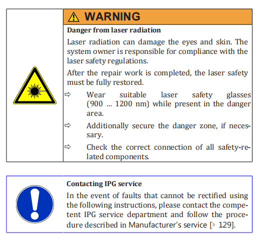
12.1.1 Messages of the Status tab
Message

Type
Status
Description
This status message is active when the laser power supply is switched
on.
The laser power supply is responsible for the supply voltage to the laser
modules.
This status is also referred to as Laser ON (Power supply ON = Laser ON).
Message

Type
Status
Description
This status message appears when the laser is operated in ROBOT mode
and the signal Internal control enabled is disabled.
Apart from the buttons Reset and E-Stop all operating functions in
LaserNet are locked in ROBOT mode. By activating the signal Internal
control enabled (depending on the communication protocol), you can
activate the internal control, i.e. the power preselection and ramping
time function (ramping rise and fall time) in LaserNet.
Message

Type
Status
Description
This status message indicates that all prerequisites for laser emission
have been met and the laser emission has been switched on (via Laser-
Net or fieldbus). This is the case even when the preselected power is
zero watts (0 W).
The following prerequisites must be met for enabling of the laser radia-
tion:
• There are no laser-related failures.
• The laser power supply is switched on (Laser power supply ON).
• The laser is in the status Laser ready.
Message

Type
Status
Description
This status message is active when the operation option External con-
trol has been enabled.
If this option is used, you can control the start and end of the laser emis-
sion via the XP2 interface (see interface description).
If you have selected the External control in the TEST mode (via Laser- Net), this remains active even after switching to the ROBOT mode.
Message

Type
Status
Description
If the operation option Analog Control is active, this status message ap-
pears (depending on the communication protocol).
If this option is enabled, you can control the laser power via the XP4-
analog interface (see interface description).
Message

Type
Status
Description
This status message is active when the control of the laser via the hardwiring interface has been enabled.
Message

Type
Status
Description
This status message is active when the guide laser of the laser is
switched on.
If a beam switch is installed, an optical path must be selected in order to
be able to see the guide laser after the process optics.
Message

Type
Status
Description
This status message indicates that all chiller parameters lie within the
specified range.
If you switch the laser on again after a prolonged pause, it may take several minutes until the specified temperatures have been reached and
the chiller outputs the status message Chiller ready.
Message

Type
Status
Description
This status message is active, if
• there is no failure pending
• the laser power supply is switched off.
12.1.2 Messages of the Alarms tab.
Message

Type
Alarm
Reset
Automatic
Description
The alarm E-Stop is activated as soon as an internal or external E-Stop
has been triggered. The E-Stop alarm usually appears in connection
with another alarm that represents the actual cause for the E-stop. The
indicator light (Interlock) on the front side of the laser lights up yellow
(Operating elements [} 31]).
Possible causes
Another alarm is output that is responsible for the E-Stop.
Fault diagnostics / troubleshooting
Correct the cause of the alarm / fault.
The alarm E-Stop will then be automatically reset.
Message

Type
Alarm
Resetting
Automatic
Description
The alarm E-Stop button is activated when the E-Stop button on the
front side of the laser cabinet is pressed. Pressing the E-Stop button
opens the internal safety circuit. The alarm leads to a shutdown of the
laser power supply and therefore the laser emission. The indicator light
(Interlock) on the front side of the laser lights up yellow.
Possible causes
E-Stop button is pressed.
Analysis / troubleshooting
ð Unlock the E-Stop button by turning 45° clockwise.
The alarm E-Stop button will then be automatically reset.
Message

Type
Alarm
Reset
Automatic
Description
The External E-Stop failure indicates that the external E-Stop circuit is
opened. The alarm leads to a shutdown of the laser power supply and
therefore the laser emission. The indicator light (Interlock) on the front
side of the laser lights up yellow.
Possible causes
• There is an alarm (E-Stop) in the safety circuit of the system owner.
• The E-Stop circuit of the system owner is not connected to the laser (safety interface, see supplied technical data).
• Only one channel of the two-circuit emergency stop system was opened or closed.
Fault diagnostics / troubleshooting
ð Rectify the operator-side failure.
ð Connect the E-Stop circuit of the system owner to the laser
(safety interface, see supplied technical data).
ð Open both channels of the E-Stop circuit to reset the failure. Activate both safety circuits again by closing both channels again.
Message

Type
Fault
Resetting
Automatic
Description
The Laser overheating alarm appears as soon as a laser module reaches a operating temperature of 35°C.
The fault leads to an immediate shutdown of the laser emission. The operating status Laser ready is reset, and the status Laser error is activated. As soon as the module temperature has fallen to 32°C, an automatic reset of the alarm takes place. The laser emission must be activated manually.
Possible causes
• Insufficient cooling of the laser modules due to incorrect parameterization of the chiller.
• Interruption of the cooling water supply to the module (e.g.
kinked or blocked hose).
Water/ Water IPG chiller
- The temperature and/or flow rate of the house water lies outside of the specifications in the technical data.
Water/air IPG chiller
- The filter pads are heavily soiled.
- The ambient temperature lies outside of the specifications in the technical data.
Analysis / troubleshooting
Contact the competent IPG service department to check the parameters.
ð Check the hose connection on the back side of the laser modules
and inside the laser.
Water/water IPG chiller
ð Check the temperature and the pressure of the house water system.
ð Check the fill level of the tap water tank in the laser chiller.
Water/air IPG chiller
ð Check the condition of the filter pads. If the filter pads are heavily soiled, they must be replaced.
ð Check the ambient temperature.
Message

Type
Alarm
Reset
Manual
Description
The alarm message Feeding fiber interlock indicates the status of the
safety circuit of the feeding fiber safety circuit.
Triggering of the Feeding fiber interlock alarm leads to an immediate
shutdown of the laser power supply and therefore the laser emission.
The operating status Laser ready is reset, and the status Laser error is
activated.
Possible causes
Possible causes
| • The feeding fiber is damaged. • The fiber connector of the feeding fiber is not (correctly) inserted into the integrated optics. • The bayonet mount is not properly connected. • The process optics are overheated. |
Fault diagnostics / troubleshooting
ð Using the guide laser, check whether the feeding fiber is optically
in good condition. If necessary, have the feeding fiber replaced.
ð Check whether the feeding fiber is correctly inserted into the integrated optics.
ð Check whether the bayonet mount is correctly connected.
ð Check the temperature at the fiber receptacle of the optics. At a
temperature of 70°C, the temperature sensors in the fiber receptacle interrupt the safety circuit.
ð If the temperature at the fiber receptacle is too high, you should
- check the welding parameters (back reflection may be too high).
- allow the fiber receptacle to cool.
After cooling the fiber receptacle, the error can be reset.
Message

Type
Fault
Resetting
Manual
Description
The alarm High back reflection is activated when the detected level of
back scattered laser radiation in the combiner module is too high. The
fault leads to an immediate shutdown of the laser emission. The operating status Laser ready is reset, and the status Laser error is activated. If
the fault occurs repeatedly, this may lead to the laser being damaged.
Possible causes
The back reflection generally occurs on the workpiece when the process parameters are not configured optimally or during the processing of highly reflective materials.
Soiling or damage to the following elements can also cause high back reflection:
- Quartz-block end faces of the feeding fiber
- Quartz-block end faces of the process fiber
- Protective glass of the process fiber
- Protective glass of the process optics
Analysis / troubleshooting
ð Check the relevant process parameters (in particular the focus position, laser power, process speed and set angle of the process optics).
ð Contact the competent IPG service department to determine the process parameters for processing highly reflective materials.
ð Check the quartz-block end faces as well as the protective glasses of the process fiber and the process optics for soiling or damage.
Message

Type
Fault
Resetting
–
Description
The alarm Laser module indicates that a previously active laser module has been deactivated due to an internal fault. The alarm leads to the shutdown of the laser emission. The operating status Laser ready is reset, and the status Laser error is activated.
Possible causes
- The module has lost communication with the micro controller.
- There is an internal module error.
Analysis / troubleshooting
ð Make certain that the communication cable between the module and the cross-connection board is connected.
ð Determine based on the Modules tab which module is deactivated.
Message

Type Fault
Resetting –
Description
The alarm Laser module disconnected can be activated depending on the configuration. It appears when the laser control loses connection to one of the laser modules. The alarm leads to the shutdown of the laser emission. The operating status Laser ready is reset, and the status Laser error is activated. For single-mode lasers, the alarm Critical error is activated.
Possible causes
- The laser control has lost the connection to one of the laser modules.
Analysis / troubleshooting
ð Ensure that the communication cable between the laser modules
and the laser control is connected.
ð Contact the competent IPG service department if the problem cannot be corrected ( Behavior in the event of malfunctions [} 129] ).
Message

Type Fault
Reset Manual
Description
The alarm Chiller is activated when a multiple failure is present at the laser chiller. The operating status Laser ready is reset, and the status Laser failure is activated.
Possible causes
- The laser chiller is not switched on.
- Thereis no communication between the laser chiller and the laser.
- Insufficient water in the tap water or DI-water tank.
- High pressure alarm
- Low pressure alarm
- Sensor error
- Overcurrent
- Electrical phase connection is wrong.
Fault diagnostics / troubleshooting
ð Using the Chiller tab, determine what type of failure this is.
ð For a detailed failure analysis see Messages on the Chiller tab.
Messages

Type Fault
Resetting –
Description
The alarm Combiner appears when a fault is present in the combiner module. The alarm leads to a shutdown of the laser power supply and therefore the laser emission. The operating status Laser ready is reset, and the status Laser error is activated. In addition, the alarm Critical er- ror is activated.
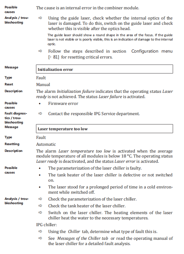
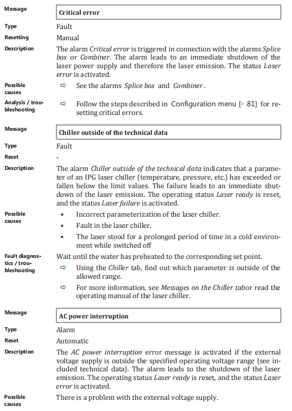

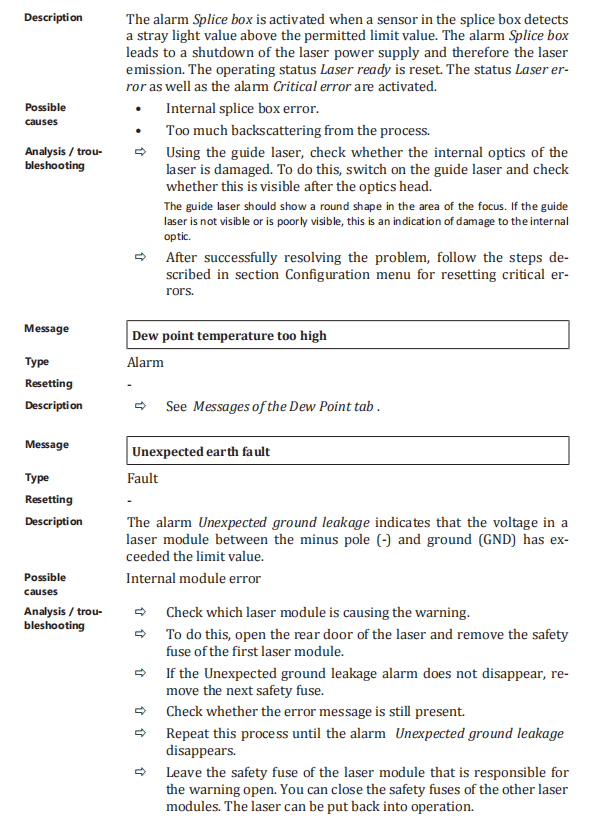
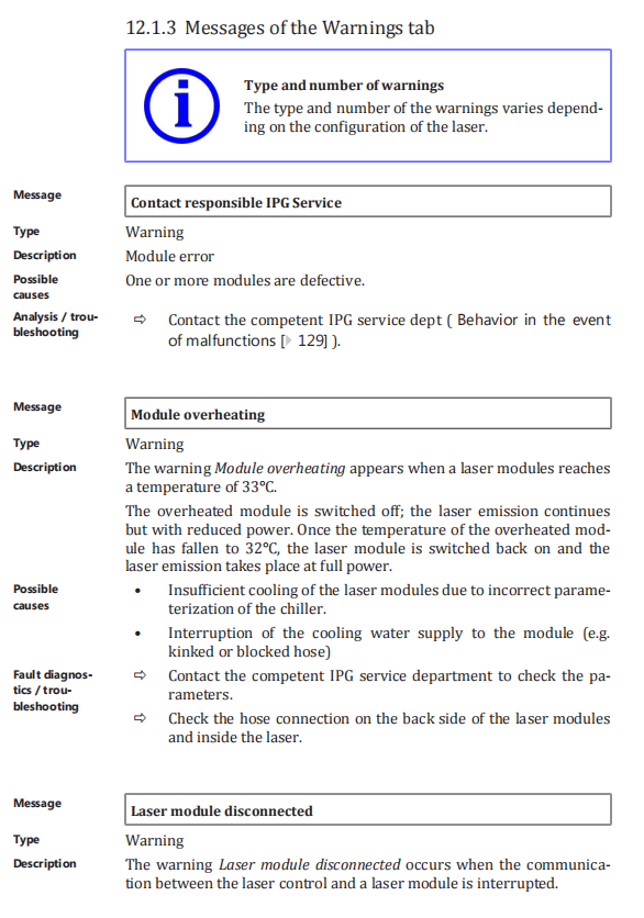
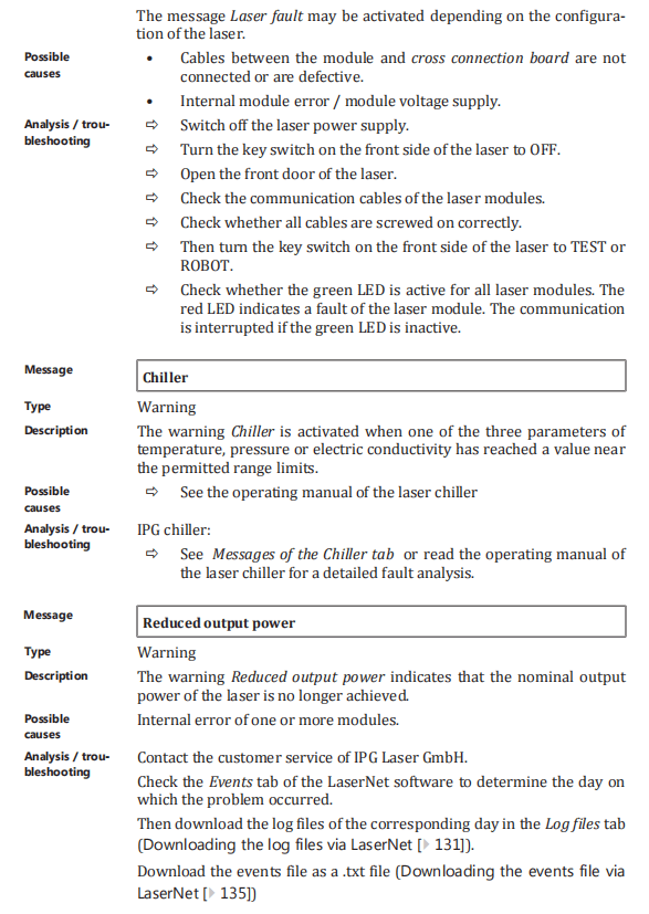
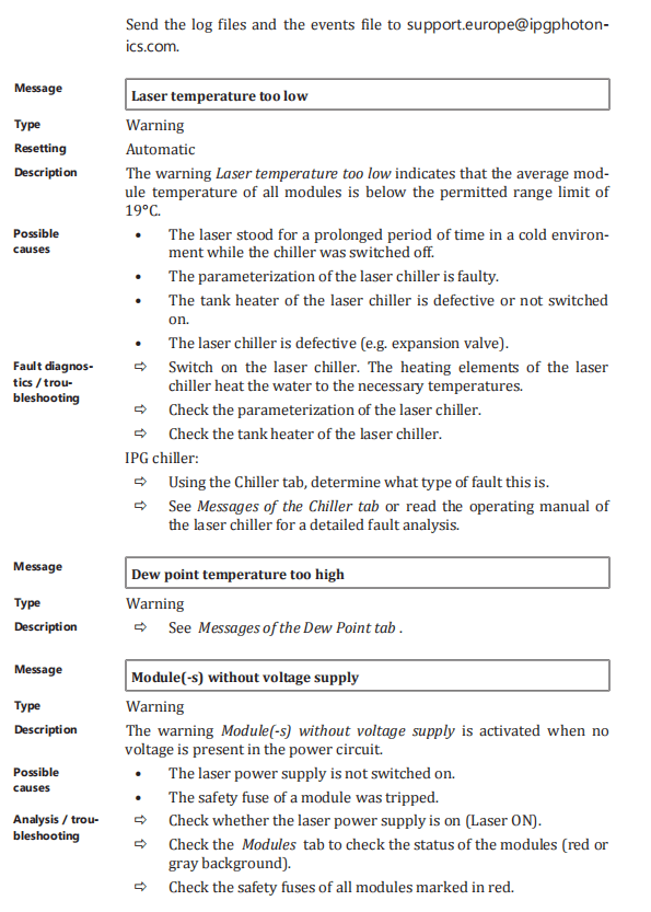
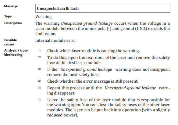
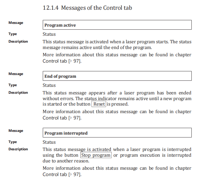
12.2 Technical data

12.2.1 Scale drawings
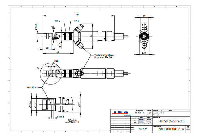
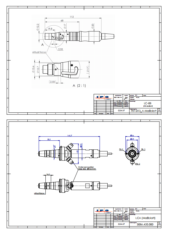
12.2.2 Rating plate of the laser
The rating plate of the laser is located on the laser cabinet and contains the following information:

12.2.3 Dew point temperatures
| Condensation: Condensate / cooling water temperature | In order to prevent damage to the laser or the optics due to condensation, the cooling water temperature must be adjusted according to the dew point table. The problem of condensation occurs in environments with high temperature and humidity. To prevent condensation, the cooling water temperature must always be kept above the dew point. |

12.3 EU Declaration of Conformity

Directory of figures
Figure 1 Safety features ……………………………………………………………………………………………… 24
Figure 2 Functional principle of the high power fiber laser………………………………. 29
Figure 3 Overview of the laser using YLS-3000-K as example ………………………….. 30
Figure 4 Operating elements …………………………………………………………………………………….. 31
Figure 5 Interfaces and connections ……………………………………………………………………….. 32
Figure 6 Fiber connector with accessories…………………………………………………………….. 32
Figure 7 Overview: fiber connectors……………………………………………………………………….. 33
Figure 8 Main components………………………………………………………………………………………… 34
Figure 9 Electrical mounting plate YLS-3000-K……………………………………………………. 35
Figure 10 Shock monitoring………………………………………………………………………………………… 36
Figure 11 Tip monitoring……………………………………………………………………………………………… 37
Figure 12 Threads for eye bolts………………………………………………………………………………….. 38
Figure 13 Removing the upper cover………………………………………………………………………… 39
Figure 14 Tensile load on the eye bolt………………………………………………………………………. 40
Figure 15 Suspension angle during crane transport ……………………………………………… 40
Figure 16 Caster with fixing device……………………………………………………………………………. 41
Figure 17 Transport with pallet………………………………………………………………………………….. 42
Figure 18 Removing covers …………………………………………………………………………………………. 48
Figure 19 Connection of the supply voltage …………………………………………………………….. 49
Figure 20 Additional earthing connection ……………………………………………………………….. 49
Figure 21 Connecting the external interfaces………………………………………………………….. 50
Figure 22 Fiber connectors with and without protective cap ……………………………… 51
Figure 23 Water connections………………………………………………………………………………………. 54
Figure 24 Control tab…………………………………………………………………………………………………….. 62
Figure 25 Program sequence example………………………………………………………………………. 69
Figure 26 Setup LaserNet welcome window……………………………………………………………. 71
Figure 27 Setup LaserNet – Destination location…………………………………………………….. 71
Figure 28 Setup LaserNet – Selecting the Start menu folder ………………………………… 72
Figure 29 Setup LaserNet – Additional tasks……………………………………………………………. 72
Figure 30 Setup LaserNet – Installing the software………………………………………………… 73
Figure 31 Setup LaserNet – Finishing the installation……………………………………………. 73
Figure 32 Internet Protocol Properties …………………………………………………………………….. 74
Figure 33 LaserNet no connection……………………………………………………………………………… 75
Figure 34 IP Configuration dialog window………………………………………………………………. 75
Figure 35 LaserNet status tab (example) …………………………………………………………………. 77
Figure 36 LaserNet user interface ……………………………………………………………………………… 77
Figure 37 Monitor file settings……………………………………………………………………………………. 80
Figure 38 IP Configuration activated…………………………………………………………………………. 81
Figure 39 IP Properties…………………………………………………………………………………………………. 81
Figure 40 Reset Critical Errors……………………………………………………………………………………. 82
Figure 41 Fieldbus Settings …………………………………………………………………………………………. 83
Figure 42 Advanced settings……………………………………………………………………………………….. 85
Figure 43 Operator power display adjustment……………………………………………………….. 86
Figure 44 Operator-specific power display ……………………………………………………………… 86
Figure 45 Change Password ………………………………………………………………………………………… 87
Figure 46 Registry Editor …………………………………………………………………………………………….. 88
Figure 47 Control Options……………………………………………………………………………………………. 88
Figure 48 Set event number for event list (events4.dat)………………………………………. 89
Figure 49 Configuring the save locations for LaserNet files…………………………………. 89
Figure 50 Overview of access rights ………………………………………………………………………….. 91
Figure 51 Password entry ……………………………………………………………………………………………. 92
Figure 52 Change Password ………………………………………………………………………………………… 92
Figure 53 Fieldbus Debug Window (PROFINET example) …………………………………… 92
Figure 54 Status tab ………………………………………………………………………………………………………. 94
Figure 55 Alarms tab …………………………………………………………………………………………………….. 95
Figure 56 Warnings tab………………………………………………………………………………………………… 96
Figure 57 Control tab…………………………………………………………………………………………………….. 97
Figure 58 Events tab ……………………………………………………………………………………………………… 99
Figure 59 Logfiles tab……………………………………………………………………………………………………. 100
Figure 60 Power supply tab…………………………………………………………………………………………. 101
Figure 61 Chiller tab status………………………………………………………………………………………….. 102
Figure 62 Chiller tab alarms………………………………………………………………………………………… 103
Figure 63 Chiller tab warnings……………………………………………………………………………………. 103
Figure 64 Dew point tab……………………………………………………………………………………………….. 104
Figure 65 Hardwiring tab …………………………………………………………………………………………….. 105
Figure 66 Modules tab…………………………………………………………………………………………………… 105
Figure 67 LaserNet program editor editing window……………………………………………… 107
Figure 68 Saving the laser program…………………………………………………………………………… 108
Figure 69 Unplugging fiber connectors (here: a HLC-8 fiber plug into an FCH-8 adapter)…………………………………………………………………………………………….. 115
Figure 70 Microscope with fiber connector …………………………………………………………….. 115
Figure 71 Fiber connector with accessories…………………………………………………………….. 116
Figure 72 Cleaning the quartz-block end-face…………………………………………………………. 119
Figure 73 Plugging fiber connectors (here: a HLC-8 fiber plug into an FCH-8 adapter)…………………………………………………………………………………………………………. 120
Figure 74 Securing the fiber connector…………………………………………………………………….. 120
Figure 75 Water drain in the cabinet bottom ………………………………………………………….. 123
Figure 76 Removing the left cover……………………………………………………………………………… 124
Figure 77 Replacing the water drain …………………………………………………………………………. 124
Figure 78 Downloading log files …………………………………………………………………………………. 131
Figure 79 Select date……………………………………………………………………………………………………… 132
Figure 80 Storage path for log files ……………………………………………………………………………. 133
Figure 81 Selecting log files …………………………………………………………………………………………. 134
Figure 82 Zip All……………………………………………………………………………………………………………… 134
Figure 83 Saving events to a .txt file ………………………………………………………………………….. 135
Figure 84 Selecting the save location ………………………………………………………………………… 136
Figure 85 Opening the configuration overview………………………………………………………. 137
Figure 86 Configuration overview……………………………………………………………………………… 137
Figure 87 Updating the configuration……………………………………………………………………….. 138
Figure 88 Selecting the HPLP file ……………………………………………………………………………….. 139
Figure 89 Update progress…………………………………………………………………………………………… 139
Figure 90 Resetting critical errors……………………………………………………………………………… 140
Figure 91 rating plate……………………………………………………………………………………………………. 164
Directory of tables
Table 1 Layout conventions………………………………………………………………………………………………… 13
Table 2 List of abbreviations………………………………………………………………………………………………. 14
Table 3 Warning labels ………………………………………………………………………………………………………… 26
Table 4 Explanatory labels………………………………………………………………………………………………….. 26
Table 5 Required supply voltage……………………………………………………………………………………….. 45
Table 6 Possible interfaces………………………………………………………………………………………………….. 50
Table 7 Standard IP address……………………………………………………………………………………………….. 74
Table 8 Description of the LaserNet user interface……………………………………………………….. 78
Table 9 LaserNet menu structure ……………………………………………………………………………………… 79
Table 10 Control Options……………………………………………………………………………………………………….. 88
Table 11 Configuration default settings……………………………………………………………………………… 90
Table 12 Description of the LaserNet status indicators …………………………………………………. 93
Table 13 Control tab description …………………………………………………………………………………………. 97
Table 14 Events tab symbol descriptions ………………………………………………………………………….. 99
Table 15 Power supply tab description ……………………………………………………………………………… 101
Table 16 Dew point tab description ……………………………………………………………………………………. 104
Table 17 Modules tab description ……………………………………………………………………………………….. 106
Table 18 Modules tab description ……………………………………………………………………………………….. 108
Table 19 Using the protective conduit………………………………………………………………………………… 117
Table 20 Using the protective glass …………………………………………………………………………………….. 117
Table 21 Dew point table……………………………………………………………………………………………………….. 165